
Related Manuals for Baxi Solo 3


Summary of Contents for Baxi Solo 3
-
Page 1: Installation And Servicing Instructions
Please leave these instructions with the user Baxi Solo 3 PFL System Wall Mounted Powered Flue System Boiler Gas Fired Central Heating Unit Installation and Servicing Instructions Supplied By www.heating spares.co Tel. 0161 620 6677... - Page 2 Product/Production certified by: Notified Body 0086. We hope you get a satisfactory service from Baxi. If For use in GB/IE only not, please let us know. Baxi is a BS-EN ISO 9001 Accredited Company Supplied By www.heating spares.co Tel.
-
Page 3: Table Of Contents
Contents Section Page Introduction General Layout Technical Data System Details Site Requirement Installation Commissioning the Appliance Fitting the Outercase Overheat Cut-Off Device 10.0 Annual Servicing 11.0 Changing Components 12.0 Short Parts List 13.0 Fault Finding Supplied By www.heating spares.co Tel. 0161 620 6677... -
Page 4: Introduction
1.0 Introduction Description 1. The Baxi Solo 3 PFL System is a gas fired room sealed fan assisted central heating system boiler with outputs as shown in the table below. Model Heat Output 8.79kW (30,000 Btu/h) 11.72kW (40,000 Btu/h) 14.65kW (50,000 Btu/h) 17.58kW (60,000 Btu/h) -
Page 5: General Layout
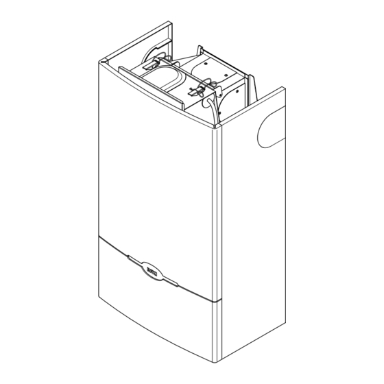
2.0 General Layout Layout (Figs. 3 & 4) Wall Plate Automatic Air Vent Expansion Vessel Pressure Relief Valve Circulation Pump Water Pressure Gauge Fig. 3 Position of Optional Timer Gas Tap Control Knob Electronics Housing Gas Valve Burner Heat Exchanger Fan Assembly Pressure Switch Overheat Thermostat... -
Page 6: Technical Data
3.0 Technical Data Model Heat Output 8.79 11.72 14.65 17.58 20.5 23.44 Btu/h 30,000 40,000 50,000 60,000 70,000 80,00 Heat Input 10.99 14.65 18.32 21.98 25.64 29.31 Btu/h 37,500 50,000 62,500 75,000 87,500 100,000 Burner Pressure mbar 16.0 ±0.5 16.0 ±0.5 16.0 ±0.5 16.0 ±0.5 16.0 ±0.5... - Page 7 242628 30 Water Flow Rate litres / min Water Flow Rate litres / min 60, 70 and 80 models 30, 40 and 50 models Top of Outercase SEDBUK Declaration For Solo 3 PFL System Model Seasonal Efficiency (SEDBUK) (%) 120mm 79.4 78.4...
-
Page 8: Water Circulating Systems
For all boilers a minimum of 6 metres of • For information or advice regarding any of the 22mm copper pipe, (measured between the above contact the Baxi Helpline. boiler flow and return connections). It Vent should be fitted with a lock shield valve... - Page 9 Thermal Stores & Heat Stores 1. If a thermal store or heat store is being used, it should be one approved for use with the Baxi Solo 3 PFL System Boiler. Supplied By www.heating spares.co Tel. 0161 620 6677...
-
Page 10: System Filling And Pressurising
4.0 System Details System Filling and Pressurising 1. A filling point connection on the central heating return pipework must be provided to facilitate initial Double filling and pressurising and also any subsequent Check water loss replacement/refilling. Valve 2. The filling method adopted must be in Stop Valve accordance with all relevant water supply bye-laws and use approved equipment. -
Page 11: Site Requirement
5.0 Site Requirements Location 1. The appliance may be fitted to any suitable wall with the flue passing through an outside wall and discharging to atmosphere in a position permitting satisfactory removal of combustion products and providing an adequate air supply. The appliance should be fitted within the building unless otherwise protected by a suitable enclosure ie. -
Page 12: Site Requirements
WARNING - The addition of anything that may interfere with the normal operation of the appliance (e.g. FLUE DAMPERS, ECONOMISERS,etc.) without the express written permission of Baxi UK Limited could invalidate the appliance warranty and infringe the GAS SAFETY (Installation and Use) REGULATIONS. - Page 13 5.0 Site Requirements Ventilation of Compartments 1. Where the appliance is installed in a cupboard or compartment, no air vents are required. NOTE: The ventilation label on the front of the outer case MUST NOT BE REMOVED when the appliance is installed in a compartment or cupboard.
-
Page 14: Installation
(Fig. 14). Place the combustion box and backplate on its back. Fig. 13 IMPORTANT - When installing a Solo 3 System with a rear flue see section 6.2 Fan Outlet Restrictor before continuing the installation. - Page 15 From Outercase To Edge Of Template Edge Of Template can be used for additional securing of the combustion box assembly to the wall. Points X Solo 3 System Boiler must be used when the optional security kit is Profile of used. TEMPLATE Outercase 4.
- Page 16 6.0 Installation Fan Outlet Restrictor 5 Pin Electrical Plug Rear Flue only up to 500mm (19 1. Release the four latches holding the combustion box door (Fig 16). Remove the combustion box door by pulling forward (Fig. 16). Fig. 15 2.
- Page 17 6.0 Installation Wall Thickness Rear Flue Preparation Wall thickness 285mm - 500mm (11 - 19 ) go Fig. 19 to section 5.6. Wall Thickness 100mm - 284mm (4in - 11 If the wall thickness is less than 285mm (11 in), Waste Wall Thickness it will be necessary to cut the components of the...
- Page 18 6.0 Installation Assembly of Rear Flue 1. Remove the rear air box blanking plate from the wall plate by releasing the three screws (Fig. 25). 2. Remove the blanking cap at the rear of the turret, by pushing and turning anti-clockwise to release the bayonet fitting (Fig.
- Page 19 6.0 Installation Fitting the Wall Plate 1. Engage the assembly into the hole previously cut in the wall and slide in place (Fig. 28). 2. Secure the assembly to the wall at the previously drilled anchorage points with suitable screws. Before finally tightening the screws, check that the assembly is level.
- Page 20 Maximum lengths for side flue using the standard telescopic flue kit 6.0 Installation Left or Right Flue NOTE: If the flue terminal is inaccessible from 355mm 335mm outside the building, it is necessary to fix the internal fitting kit in position before continuing with the installation.
- Page 21 6.0 Installation Wall Thickness Side Flue Preparation 1. For both Left and Right Hand Flue - Measure the distance from the wall to the nearest line Fig. 38 marked from the template. This will be known as Fig. 37 dimension X (Fig. 37). Total Flue Length Wall Thickness 145mm (Left Hand Flue)
- Page 22 6.0 Installation Fitting the Flue and Wall Plate 1. NOTE: There are two options for fitting the flue and wall plate they are: Method A - Fitting the flue and wall plate as an assembly (usually used where there are no side clearance problems).
- Page 23 6.0 Installation 6.10 Method A (Cont) 7. Engage the assembly into the hole previously cut in the wall and slide into place (Fig. 50). 8. Secure the assembly to the wall at the previously drilled anchorage points with suitable screws. Before finally tightening the screws, check that the assembly is level.
- Page 24 6.0 Installation 6.11 Method B 1. Remove the left or right hand air box blanking plate, as appropriate, from the back plate air box by releasing the three screws (Fig. 54). 2. Rotate the turret to face the selected opening (Fig.
- Page 25 6.0 Installation 6.12 Terminal Guard 1. When codes of practice dictate the use of terminal guards, they can be obtained from most plumbers and builders merchants nationwide. 2. When ordering a terminal guard, quote the appliance model number. 3. There must be a clearance of at least 50mm between any part of the terminal and the guard.
- Page 26 6.0 Installation 6.14 Internal Fitting Kit 1. The internal fitting kit (available from merchants quoting Baxi Part N . 236441) is Wall Thickness suitable for walls between 100mm (4in) and 285mm (11 in) in thickness. 2. TO INSTALL THE KIT - Mark the flue hole centre as described in section 6.3 or 6.8.
- Page 27 6.0 Installation 6.14 Internal Fitting Kit (Cont) 6. Refit the end piece to the liner and open out to Fig. 64 the thickness of the wall. Seal the two pieces together using the tape provided with the kit (Fig 64). 7.
- Page 28 6.0 Installation 6.15 Connection and Flushing 1. Connect the gas, water and pressure relief discharge pipes to the valves on the wall plate using the copper tails supplied. Ensure that the sealing washers are fitted correctly to the water connections. 2.
- Page 29 6.0 Installation Retaining Latch 6.16 Fitting the Combustion Box Assembly CAUTION: Care must be taken when lifting the boiler on to the backplate. Get assistance Wall Plate if required. Fig. 69 1. Remove the sealing tape from the taps. 2. Offer the combustion box assembly up to the wall plate and locate the slots on the back plate Back Plate Slots on to the hooks on the wall plate (Fig 70 &...
- Page 30 6.0 Installation 6.17 Electrical Connections Pressure Switch Gas Valve Spark Electrode or/bk or/bk Pump Control Potentiometer & Switch Thermostat Sensor br - brown b - blue r - red w - white bk - black or - orange gy - grey y - yellow Overheat g - green...
- Page 31 6.0 Installation 6.18 Making the Electrical Connections 1. Remove the cover from the control box by removing the 2 screws (Fig. 74). 2. Slide the box forward for easier access. 3. Route the supply cable via the control box from the rear of the appliance.
-
Page 32: Commissioning The Appliance
7.0 Commissioning the Appliance Commissioning the Appliance 1. Pressurise the system to 1.0 bar then close and disconnect the filling loop. Check for water leaks. 2. Purge away air from the supply pipe at the gas service cock. (BS 6891: 1988) (Fig. 78). 3. - Page 33 7.0 Commissioning the Appliance Input P Setting Pressure Model Commissioning the Appliance (Cont) Btu/h mbar in wg 16.0 + 0.5 6.4 + 0.2 1. The burner pressure is factory set. 10.99 37, 500 2. From the table opposite check that the main 16.0 + 0.5 6.4 + 0.2 14.65...
-
Page 34: Fitting The Outercase
8.0 Fitting the Outercase Fitting the Outercase 1. The warning label may be removed unless the boiler is to be fitted within a cupboard or compartment. 2. If the appliance is flued to the left or to the Hooks right, remove the relevant infill panel from the case by removing the retaining clips and fixing Fig. -
Page 35: Overheat Cut-Off Device
9.0 Overheat Cut-off Device Operation 1. The overheat cut-off device is of the manual reset type and therefore it is important that the user knows how to reset the control should it ever operate. NOTE: Cut-off is indicated by illumination of the overheat neon light on the control box. -
Page 36: Annual Servicing
10.0 Annual Servicing 10.1 Dismantling the Boiler 1. For reasons of safety and economy the boiler should be serviced annually. ( For location of British Gas service test point see Changing Components section of these instructions). Fig. 91 2. Before servicing the boiler please read Section 1.3 Important Information. - Page 37 Baffle Retaining Clip 10.0 Annual Servicing Fig. 95a 10.2 Cleaning the Combustion Box Fig. 96 1. Remove the burner assembly by pulling it forward (Fig. 97). 2. Lightly brush any dirt from the top of the burner blades and ensure that the ports are free from obstruction.
-
Page 38: Changing Components
British Gas Service Test Point. 11.0 Changing Components For use by B.G. Personnel only 11.1 Changing Components 1. Before changing any components ensure that the gas and electrical supplies are isolated. 2. Before changing any components please read Section 1.3 Important Information. 3. - Page 39 11.0 Changing Components 11.4 Gas Valve (Fig. 110 & 111) 1. Undo the turn screws and drop the facia panel down. 2. Disconnect the electrical connections from the valve, noting their positions. 3. Undo the screw retaining the valve cover and remove the cover.
- Page 40 11.0 Changing Components Fig. 114 11.7 Changing Components (Cont) 1. To change Fan - Pressure Switch - Burner - Burner Injector - Pilot Burner Injector - Gas Manifold, proceed as follows:- 2. Release the four latches holding the combustion box door. Remove the combustion box door by Combustion Box Door pulling forward from the bottom and unhooking its top edge (Fig.
- Page 41 11.0 Changing Components 11.10 Burner (Fig. 118) 1. Remove the burner assembly by pulling it forward. 2. Fit new burner and re-assemble all components in reverse order of dismantling. Fig. 118 11.11 Burner Injector (Fig. 120) 1. Release and remove the burner injector which is screwed into the burner feed manifold.
- Page 42 11.0 Changing Components 11.15 Pump (Head Only) (Fig. 128) 1. If only the head needs replacing. A standard Grundfos UPS 15-60 pump head is interchangeable. 2. Isolate the appliance from the water system by closing the flow and return taps. 3.
- Page 43 11.0 Changing Components 11.16 Pressure Gauge 1. Isolate the appliance from the water system by closing the flow and return taps. 2. Drain the boiler of water. 3. Undo the turn screws and drop the facia panel down. 4. Undo the nut on the gauge capillary at the boiler flow connection (Fig.
-
Page 44: Short Parts List
12.0 Short parts list 12.1 Short Parts List Description Model G.C. Manuf'rs Part N Burner 30, 40, 50 364 878 231708 60, 70, 80 364 879 231709 Burner Injector 246176 246177 246178 246161 246162 246163 Pilot Kit All models 170 558 236142 Electrode Lead All models... -
Page 45: Fault Finding
13.0 Fault Finding Before starting FAULT FINDING carry out preliminary electrical system checks i.e. Earth Continuity, Polarity, Short Circuit and Resistance to Earth. Ensure that the system is correctly pressurised. START there a clear constant spark at Does pump run ? Does fan run ? the electrode ? Ensure external... - Page 46 13.0 Fault Finding Does Does Does the boiler shut Does down when the water the pilot burner the main burner pump run flow reaches light ? light ? on ? 80-84 Boiler satisfactory Check there is 20mbar gas pressure at the inlet to gas valve "Burner On"...
- Page 47 Baxi UK Limited manufacture a comprehensive range of products for the domestic heating market. Gas Central Heating Boilers (Wall, Floor and Fireside models). Independent Gas Fires. Renewal Firefronts. Gas Wall Heaters. Solid Fuel Fires. If you require information on any of these products, please write, telephone or fax to the Sales Department.
-
Page 48: After Sales Service
Comp N 5106278 - Iss 1 - 11/01 After Sales Service 08706 096 096 Technical Enquiries 08706 049 049 Baxi UK Limited Brownedge Road Bamber Bridge Preston Lancashire PR5 6SN www.baxi.com Supplied By www.heating spares.co Tel. 0161 620 6677...
Need help?
Do you have a question about the Solo 3 and is the answer not in the manual?
Questions and answers