Baxi Solo 3 30 PF Installation And Servicing Instructions
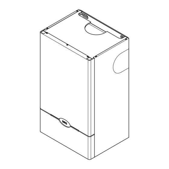
Wall mounted powered flue gas fired central heating unit
Hide thumbs
Also See for Solo 3 30 PF:
- Installation and servicing instructions (45 pages) ,
- User operating instructions manual (8 pages)

Related Manuals for Baxi Solo 3 30 PF


Summary of Contents for Baxi Solo 3 30 PF
-
Page 1: Installation And Servicing Instructions
Please leave these instructions with the user Baxi Solo 3 PF Wall Mounted Powered Flue Gas Fired Central Heating Unit Installation and Servicing Instructions... - Page 2 Product/Production certified by: Notified Body 0086. We hope you get a satisfactory service from Baxi. If For GB / IE only. not, please let us know. Baxi is a BS-EN ISO 9001...
-
Page 3: Table Of Contents
Contents Section Page Introduction Technical Data System Details Site Requirement Installation Commissioning the Appliance Fitting the Outercase Overheat Cut-Off Device Annual Servicing 10.0 Changing Components 11.0 Fault Finding 12.0 Short Parts List 13.0 Notes... -
Page 4: Introduction
1.0 Introduction Description 1. The Baxi Solo 3 PF is a gas fired room sealed fan assisted central heating boiler with range rated outputs as shown in the table below HEAT OUTPUT Q Model 5.86kW (20,000 Btu/h) 8.79kW (30,000 Btu/h) 9.09kW (31,000 Btu/h) -
Page 5: Technical Data
2.0 Technical Data Model P Heat Output (Max) 8.79 11.72 14.65 17.58 20.5 23.45 Btu/h 30,000 40,000 50,000 60,000 70,000 80,000 P Heat Output (Min) 5.86 9.09 12.02 14.95 17.88 20.8 Btu/h 20,000 31,000 41,000 51,000 61,000 71,000 Q Heat Input (Max) 10.99 14.65 18.32... - Page 6 2.0 Technical Data Hydraulic Resistance Charts (52) 130 (52) 130 (48) 120 (48) 120 (44) 110 (44) 110 (40) 100 (40) 100 (36) 90 (36) 90 (32) 80 (32) 80 (28) 70 (28) 70 (24) 60 (24) 60 (20) 50 (20) 50 (16) 40 (16) 40...
-
Page 7: System Details
Fig. 3 shows (Fig. 2). • For information or advice regarding any of the Arrangement above contact the Baxi Helpline. The bypass circuit can be:- a) For all boilers a minimum of 6 metres of 22mm copper pipe, (measured between the Bypass Requirements boiler flow and return connections). - Page 8 3.0 System Details Copper Copper 0.5m 0.5m Pipework Flow Boiler Return 1. The sizes of flow and return pipes from the Copper boiler should be determined by normal methods, according to the requirements of the system. 2. An 11 °C (20°F) drop in temperature across the Fig.
- Page 9 BS 5449 and the British Gas Method of determining minimum publication entitled 'Specifications for Domestic value of expansion vessel volume for sealed systems using Baxi Boilers Wet Central Heating Systems'. Multiply Total 4. FILLING POINT - A filling point and an...
-
Page 10: Site Requirement
4.0 Site Requirements Location 1. The appliance may be fitted to any suitable wall with the flue passing through an outside wall and discharging to atmosphere in a position permitting satisfactory removal of combustion products and providing an adequate air supply. The appliance should be fitted within the building unless otherwise protected by a suitable enclosure ie. -
Page 11: Site Requirements
15 metres in length. Horizontally from a terminal on the same wall. For an opening in a car port (e.g. door, window) IMPORTANT: Solo 3 30 PF models must not into a dwelling. 1200 be set at minimum input when installed with vertical flue systems. - Page 12 4.0 Site Requirements Ventilation of Compartments 1. Where the appliance is installed in a cupboard or compartment, no air vents are required. NOTE: The ventilation label on the front of the outer case MUST NOT BE REMOVED when the appliance is installed in a compartment or cupboard.
- Page 13 4.0 Site Requirement Flue Options 1. The Baxi Solo 3 PF can be fitted with flue systems as illustrated. 2, The standard flue is suitable only for horizontal applications. Maximum Length = 2m inc. 2 x 45° bends 3. Maximum permissible equivalent flue lengths...
-
Page 14: Installation
5.0 Installation Initial Preparation 1. Unpack contents of carton. 2. Remove the lower door panel from the outer case. Remove the 2 screws holding the outer case to the combustion box. 3. Place the ready assembled outer case in a safe place until required. - Page 15 5.0 Installation Fan Outlet Restrictor (30, 40, 50, 60, 70 and 80) Rear Flue only up to 500mm (19 1. Release the four latches holding the combustion box door (Fig 18). Remove the combustion box door by pulling forward (Fig. 16). Fig.
- Page 16 1. For installations where the flue terminal is inaccessible from the outside, an internal fitting kit is available. This can be obtained from your local merchant quoting Baxi Part N 236441. 2. If using the internal fitting kit a 117mm in) diameter hole is required.
- Page 17 5.0 Installation Wall Thickness Rear Flue Preparation Wall thickness 285mm - 500mm (11 - 19 ) go Fig. 22 to section 5.6. Wall thickness 100mm - 284mm (4 in - 11 in). If the wall thickness is less than 285mm (11 in), Waste Wall Thickness...
- Page 18 5.0 Installation Blanking Assembly of Rear Flue 1. Remove the rear air box blanking plate from the back plate by releasing the three screws (Fig. 27). 2. Remove the blanking cap at the rear of the turret, by pushing and turning anti-clockwise to release the bayonet fitting (Fig.
- Page 19 5.0 Installation Fitting the Back Plate 1. Engage the assembly into the hole previously cut in the wall and slide in place (Fig. 31). 2. Secure the assembly to the wall at the previously drilled anchorage points with suitable screws (Fig. 31). Before finally tightening the screws, check that the assembly is level.
- Page 20 5.0 Installation Maximum lengths for side flues using the standard telescopic flue kit 410mm (30, 40, 50) 410mm (30, 40, 50) 355mm (60, 70, 80) 355mm (60, 70, 80) Left or Right Flue Concentric flue kits are available to allow 3 metres horizontal and 4 metres vertical flueing.
- Page 21 5.0 Installation Wall Thickness Side Flue Preparation 1. For both Left and Right Hand Flue - Measure the distance from the wall to the nearest line Fig. 40 Fig. 41 marked from the template. This will be known as dimension X (Fig. 40). Total Flue Length 2.
- Page 22 5.0 Installation 5.10 Fitting the Flue and Back Plate 1. NOTE: There are two options for fitting the flue and back plate they are: Method A - Fitting the flue and back plate as an assembly (usually used where there are no side clearance problems).
- Page 23 5.0 Installation 5.11 Method A (Cont) 7. Engage the assembly into the hole previously cut in the wall and slide into place. 8. Secure the assembly to the wall at the previously drilled anchorage points with suitable screws. Before finally tightening the screws, check that the assembly is level (Fig.
- Page 24 5.0 Installation 5.12 Method B 1. Remove the left or right hand air box blanking plate, as appropriate, from the back plate air box by releasing the three screws (Fig. 54). 2. Rotate the turret to face the selected opening (Fig.
- Page 25 5.0 Installation 5.13 Terminal Guard 1. When codes of practice dictate the use of terminal guards, they can be obtained from most plumbers and builders merchants nationwide. 2. When ordering a terminal guard, quote the appliance name and model number. 3.
- Page 26 5.0 Installation 5.15 Internal Fitting Kit 1. The internal fitting kit (available from merchants free of charge quoting Baxi Part Wall Thickness . 236441) is suitable for walls between 100mm (4in) and 285mm (11 in) in thickness. 2. TO INSTALL THE KIT - Mark the flue hole centre as described in section 5.4 or 5.8.
- Page 27 5.0 Installation 5.15 Internal Fitting Kit (Cont) 6. Refit the end piece to the liner and open out to Fig. 65 the thickness of the wall. Seal the two pieces together using the tape provided with the kit (Fig 65). 7.
- Page 28 5.0 Installation 5.16 Fitting the Combustion Box 1. Offer up the combustion box to the back plate and locate the rear bottom edge of the combustion box onto the self locating support at the base of the wall plate (Fig. 70). 2.
- Page 29 5.0 Installation 5.17 Electrical Connections Pressure Switch Gas Valve Spark Electrode Overheat Thermostat Control Thermostat Sensor Potentiometer br - brown b - blue or/bk & Switch r - red w - white bk - black or - orange gy - grey y - yellow g - green g/y - green &...
- Page 30 5.0 Installation 5.18 Making the Electrical Connections 1. Remove the cover from the control box by removing the 2 screws (Fig. 73). 2. Slide the box forward for easier access. 3. The terminal strips may be removed by carefully pulling them forward. Connect the supply cable and the pump cable to the terminal strips (Fig.
- Page 31 5.0 Installation 5.19 Water Connections 1. The boiler has two side water connections, the top connection being FLOW and the bottom connection being RETURN (Fig. 75a). 2. It is essential that FLOW and RETURN pipes are connected to the correct fittings. 3.
-
Page 32: Commissioning The Appliance
6.0 Commissioning the Appliance Commissioning the Appliance 1. Flush the whole system in accordance with BS 5793 (see Section 3.1 Water Circulating Systems). Check for water leaks. 2. Purge away air from the supply pipe at the gas service cock. (BS 6891) (Fig. 79). 3. - Page 33 88, 750 4. To alter the burner pressure, turn the adjustment screw in either direction until the required pressure IMPORTANT: Solo 3 30 PF models is obtained. must not be set at minimum input when installed with vertical flue systems.
-
Page 34: Fitting The Outercase
7.0 Fitting the Outercase Fitting the Outercase 1. The warning label may be removed unless the boiler is to be fitted within a cupboard. 2. Taking the ready assembled outercase, the front door of which has already been removed, Infill Panel Fig. -
Page 35: Overheat Cut-Off Device
8.0 Overheat Cut-off Device Operation 1. The overheat cut-off device is of the manual reset type and therefore it is important that the user knows how to reset the control should it ever cut out. NOTE: Cut-out is indicated by illumination of the neon light on the control box. -
Page 36: Annual Servicing
9.0 Annual Servicing Dismantling the Boiler 1. To ensure its continued safe and efficient operation, it is important that the appliance is regularly serviced. ( For location of British Gas service test point see Changing Components section of these instructions). 2. - Page 37 9.0 Annual Servicing Baffle Retension Clip Cleaning the Combustion Box Fig. 93a 1. Remove the burner assembly by pulling it forward (Fig. 94). 2. Lightly brush any dirt from the top of the burner Baffles blades and ensure that the ports are free from obstruction.
-
Page 38: Changing Components
10.0 Changing Components 10.1 Changing Components 1. When changing components ensure that the gas and electrical supplies are isolated before the work is started. 2. Before changing any components please read Section 1.3 Important Information. 3. Remove the outer case lower door panel Fig. - Page 39 10.0 Changing Components British Gas Service Test Point. For use by B.G. Personnel only 10.3 Ignition Electrode (Fig. 104) 1. Disconnect the spark electrode lead at the electrode. 2. Unscrew the electrode from the manifold and withdraw the electrode. 3. Replace the new electrode in reverse order, ensuring that the sleeving is pushed over the end of the electrode.
- Page 40 10.0 Changing Components 10.7 Changing Components (Cont) 1. To change Fan - Pressure Switch - Burner - Burner Injector - Pilot Burner Injector - Gas Manifold, proceed as follows:- 2. Release the four latches holding the combustion Fig. 109 box door (Fig. 108). Remove the combustion box door by pulling forward (Fig.
- Page 41 10.0 Changing Components 10.10 Burner (Fig. 113) 1. Remove the burner assembly by pulling it forward. 2. Fit new burner and re-assemble all components in reverse order of dismantling. 10.11 Burner Injector (Fig. 114) 1. Release and remove the burner injector which is screwed into the burner feed manifold.
-
Page 42: Fault Finding
11.0 Fault Finding Before starting FAULT FINDING carry out preliminary electrical system checks i.e. Earth Continuity, Polarity, Short Circuit and Resistance to Earth. START there a clear constant spark at Does pump run ? Does fan run ? the electrode ? Ensure external controls are calling for heat... - Page 43 11.0 Fault Finding Does Does Does the boiler shut Does down when the water the pilot burner the main burner pump run flow reaches light ? light ? on ? 80-84 Boiler satisfactory Check there is 20mbar gas pressure at the inlet to gas valve "Burner On"...
-
Page 44: Short Parts List
12.0 Short Parts List 12.1 Short Parts List Description Model G.C. Manuf'rs Part N Burner 30-40-50 364 878 231708 60-70-80 364 879 231709 Burner Injector 364 880 231354 364 881 231355 364 882 228104 364 873 231776 E01 623 239619 364 981 231777 Pilot Kit... -
Page 45: Notes
13.0 Notes... - Page 46 13.0 Notes...
- Page 47 Baxi UK Limited manufacture a comprehensive range of products for the domestic heating market Gas Central Heating Boilers (Wall, Floor and Fireside models). Independent Gas Fires. Renewal Firefronts. Gas Wall Heaters. Solid Fuel Fires. If you require information on any of these products,...
-
Page 48: After Sales Service
Comp N 244096 - Iss 5 - 4/01 After Sales Service 08706 096 096 Technical Enquiries 08706 049 049 Baxi UK Limited Brownedge Road Bamber Bridge Preston Lancashire PR5 6SN www.baxi.com...
Need help?
Do you have a question about the Solo 3 30 PF and is the answer not in the manual?
Questions and answers