Baxi Solo 3 30 PF System Installation And Servicing Instructions
Wall mounted powered flue system boiler
gas fired central heating unit
Hide thumbs
Also See for Solo 3 30 PF System:
- User operating instructions manual (8 pages) ,
- Installation and servicing instructions (48 pages)

Related Manuals for Baxi Solo 3 30 PF System


Summary of Contents for Baxi Solo 3 30 PF System
- Page 1 Please leave these instructions with the user Baxi Solo 3PF System Wall Mounted Powered Flue System Boiler Gas Fired Central Heating Unit Comp No 245443 - Issue 1 - 9/99 Installation and Servicing Instructions...
- Page 2 Product/Production certified by: Notified Body 0086. We hope you get a satisfactory service from Baxi. If not, please let us know. For use in GB / IE only. Baxi is a BS-EN ISO 9001...
-
Page 3: Table Of Contents
Contents - Page 3 Section Page Introduction General Layout Technical Data System Details Site Requirement Installation Commissioning the Appliance Fitting the Outercase Overheat Cut-Off Device 10.0 Annual Servicing 11.0 Changing Components 12.0 Short Parts List 13.0 Fault Finding... -
Page 4: Introduction
Introduction - Page 4 1.1 Description 1. The Baxi Solo 3 PF System is a gas fired room sealed fan assisted central heating system boiler with range rated outputs as shown in the table below. 2. Each appliance is preset at a MID RANGE heat input rating and is designed for use on NATURAL GAS only. -
Page 5: General Layout
General Layout - Page 5 2.1 Layout (Figs. 3 & 4) Wall Plate Automatic Air Vent Expansion Vessel Pressure Relief Valve Circulation Pump Water Pressure Gauge Position of Optional Timer Gas Tap Control Knob 10. Electronics Housing 11. Gas Valve 12. -
Page 6: Technical Data
Technical Data - Page 6 Model Heat Output (Max) 11.72 14.65 17.58 20.5 23.45 Btu/h 30,000 40,000 50,000 60,000 70,000 80,000 Heat Output (Min) 5.86 9.09 12.02 14.95 17.88 20.8 Btu/h 20,000 31,000 41,000 51,000 61,000 71,000 Heat Input (Max) 10.99 14.65 18.32... - Page 7 Technical Data - Page 7 Hydraulic Resistance Charts • This appliance is only intended for installation on a governed supply. • PMS = 3 bar pressure class 2 • Max CH water pressure 3 bar • Type C • Nox class 2 •...
-
Page 8: System Details
• For information or advice regarding any of the above contact the Baxi Helpline. 4.3 Bypass Requirements 1. The boiler is fitted with a pump overrun device which allows the removal of residual heat from the boiler. - Page 9 & TRV’s only does not produce the best results 4.6 Thermal Stores & Heat Stores 1. If a thermal store or heat store is being used, it should be one approved for use with the Baxi Solo 3 PF System Boiler.
-
Page 10: Pressure Relief Valve
System Details - Page 10 4.7 System Filling and Pressurising 1. A filling point connection on the central heating return pipework must be provided to facilitate initial filling and pressurising and also any subsequent water loss replacement/refilling. 2. The filling method adopted must be in accordance with all relevant water supply bye-laws and use approved equipment. -
Page 11: Site Requirement
Site Requirements - Page 11 5.1 Location 1. The appliance may be fitted to any suitable wall with the flue passing through an outside wall and discharging to atmosphere in a position permitting satisfactory removal of combustion products and providing an adequate air supply. The appliance should be fitted within the building unless otherwise protected by a suitable enclosure ie. - Page 12 WARNING - The addition of anything that may interfere with the normal operation of the appliance (e.g. FLUE DAMPERS, ECONOMISERS,etc.) without the express written permission of Baxi Heating Ltd could invalidate the appliance warranty and Infringe the GAS SAFETY (Installation and Use) REGULATIONS.
- Page 13 Site Requirements - Page 13 5.5 Ventilation of Compartments 1. Where the appliance is installed in a cupboard or compartment, no air vents are required. NOTE: The ventilation label on the front of the outer case MUST NOT BE REMOVED when the appliance is installed in a compartment or cupboard.
-
Page 14: Installation
Installation - Page 14 6.1 Initial Preparation 1. Remove the hinged lower door panel from the outer case by opening it to 90º and pulling forwards (Fig. 13). 2. Remove the 2 screws holding the outer case to the combustion box (Fig. 13). 3. - Page 15 Installation - Page 15 6.2 Initial Preparation (continued) 1. Remove the fixing template (Fig. 14c) from the carton. 2. After considering the site requirements (see Section 5.2) position the template on the wall ensuring it is level both horizontally and vertically. If it is desired that the appliance is positioned centrally between two points, mark the wall accordingly and align the template centreline with this mark.
- Page 16 Installation - Page 16 6.3 Fan Outlet Restrictor Rear Flue only up to 500mm (19 1. Release the four latches holding the combustion box door (Fig 16). Remove the combustion box door by pulling forward (Fig. 16). 2. Release the 5-pin electrical plug connecting the pressure switch and fan (Fig.
- Page 17 Installation - Page 17 6.4 Rear Flue Preparation Wall thickness 285mm - 500mm (11 - 19 ) go to section 5.6. Wall thickness 100mm - 284mm (4 in - 11 in). If the wall thickness is less than 285mm (11 in), it will be necessary to cut the components of the flue to the appropriate size.
- Page 18 Installation - Page 18 6.5 Assembly of Rear Flue 1. Remove the rear air box blanking plate from the wall plate by releasing the three screws (Fig. 25). 2. Remove the blanking cap at the rear of the turret, by pushing and turning anti-clockwise to release the bayonet fitting (Fig.
- Page 19 Installation - Page 19 6.6 Fitting the Wall Plate 1. Engage the assembly into the hole previously cut in the wall and slide in place (Fig. 28). 2. Secure the assembly to the wall at the previously drilled anchorage points with suitable screws. Before finally tightening the screws, check that the assembly is level.
- Page 20 Installation - Page 20 6.7 Left or Right Flue NOTE: If the flue terminal is inaccessible from outside the building, it is necessary to fix the internal fitting kit in position before continuing with the installation. (See section 5.15 Internal Fitting Kit of these instructions). 1.
- Page 21 Installation - Page 21 6.8 Side Flue Preparation 1. For both Left and Right Hand Flue - Measure the distance from the wall to the nearest line marked from the template. This will be known as dimension X (Fig. 37). 2.
- Page 22 Installation - Page 22 6.9 Fitting the Flue and Wall Plate 1. NOTE: There are two options for fining the flue and wall plate they are: Method A - Fitting the flue and wall plate as an assembly (usually used where there are no side clearance problems). Method B - Pre-fitting the flue through the wall, fitting the wall plate to its position on the wall and then connecting the two together (usually used where side clearances are...
- Page 23 Installation - Page 23 6.10 Method A (Cont) 7. Engage the assembly into the hole previously cut in the wall and slide into place (Fig. 50). 8. Secure the assembly to the wall at the previously drilled anchorage points with suitable screws. Before finally tightening the screws, check that the assembly is level.
- Page 24 Installation - Page 24 6.11 Method B 1. Remove the left or right hand air box blanking plate, as appropriate, from the back plate air box by releasing the three screws (Fig. 54). 2. Rotate the turret to face the selected opening (Fig. 53) and remove the side blanking cap by pushing in and turning anti-clockwise to release the bayonet fitting (Fig.
- Page 25 Installation - Page 25 6.12 Terminal Guard 1. When codes of practice dictate the use of terminal guards, they can be obtained from most plumbers and builders merchants nationwide. 2. When ordering a terminal guard, quote the appliance model number. 3.
- Page 26 Installation - Page 26 6.14 Internal Fitting Kit 1. The intemal fitting kit (available from merchants quoting Baxi Part N . 236441) is suitable for walls between 100mm (4in) and 285mm (11 in) in thickness. 2. TO INSTALL THE KIT - Mark the flue hole centre as described in section 6.3 or 6.8.
- Page 27 Installation - Page 27 6.14 Internal Fitting Kit (Cont) 6. Refit the end piece to the liner and open out to the thickness of the wall. Seal the two pieces together using the tape provided with the kit (Fig 64). 7.
- Page 28 Installation - Page 28 6.15 Connection and Flushing 1. Connect the gas, water and pressure relief discharge pipes to the valves on the wall plate using the copper tails supplied. Ensure that the sealing washers are fitted correctly to the water connections. 2.
- Page 29 Installation - Page 29 Fitting the Combustion Box Assembly CAUTION: Care must be taken when lifting the boiler on backplate. Get assistance if required. 1. Remove the sealing tape from the taps. and locate the slots on the back plate on to the hooks on the wall plate (Fig 70 &...
- Page 30 Installation - Page 30 6.17 Electrical Connections...
- Page 31 Installation - Page 31 6.18 Making the Electrical Connections 1. Remove the cover from the control box by removing the 2 screws (Fig. 74). 2. Slide the box forward for easier access. 3. Route the supply cable via the control box from the rear of the appliance.
-
Page 32: Commissioning The Appliance
Commissioning the Appliance - Page 32 7.1 Commissioning the Appliance disconnect the filling loop. Check for water leaks. 2. Purge away air from the supply pipe at the gas service 3. Ensure that the electrical supply is isolated. 4. Check the electrical supply for earth continuity, polarity, 5. - Page 33 Commissioning the Appliance - Page 33 7.1 Commissioning the Appliance (Cont) 1. From the table opposite check that the main burner pressure is correct after the appliance has been running for 10 minutes. 2. Check for gas soundness, with main burner alight, using leak detection fluid.
-
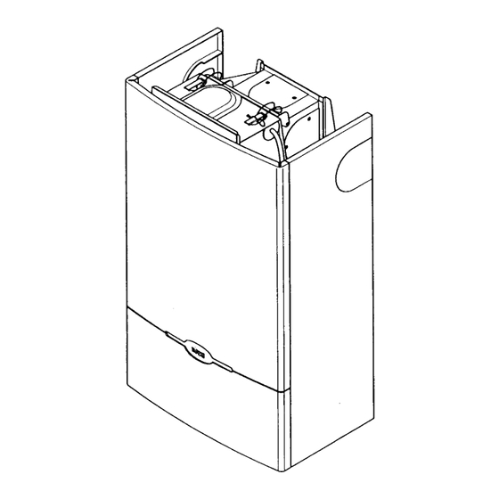
Page 34: Fitting The Outercase
Fitting the Outercase - Page 34 8.1 Fitting the Outercase 1. The warning label may be removed unless the boiler is to be fitted within a cupboard or compartment. 2. If the appliance is flued to the left or to the right, remove the relevant infill panel from the case by removing the retaining clips and fixing screws (Fig. -
Page 35: Overheat Cut-Off Device
Overheat Cut-off Device - Page 35 Operation 1. The overheat cut-off device is of the manual reset type the control should it ever operate. NOTE: Cut-off is indicated by illumination of the 2. Hinge the lower door panel down (Fig 89). - Turn the boiler thermostat control knob fully anti-clockwise to the OFF position marked ‘0’... -
Page 36: Annual Servicing
10.0 Annual Servicing - Page 36 10.1 Dismantling the Boiler 1. For reasons of safety and economy the boiler should be serviced annually. (For location of British Gas service test point see Changing Components section of these instructions). 2. Before servicing the boiler please read Section 1.3 Important Information. - Page 37 10.0 Annual Servicing - Page 37 10.2 Cleaning the Combustion Box 1. Remove the burner assembly by pulling it forward (Fig. 97). 2. Lightly brush any dirt from the top of the burner blades and ensure that the ports are free from obstruction. baffle retaining clip and lift the baffles from the heat exchanger (Fig.
-
Page 38: Changing Components
11.0 Changing Components - Page 38 Changing Components 1. Before changing any components ensure that the gas 2. Before changing any components please read Section 1.3 Important Information. right to remove. 4. Remove the outer case from the boiler by unscrewing the 11.2 Replacing the Ci 1. - Page 39 11.0 Changing Components - Page 39 11.4 Gas Valve (Fig.110& 111) 1. Undo the ¼ turn screws and drop the facia panel down. 2. Disconnect the electrical connections from the valve, noting their positions. cover. 4. Undo the nut on the valve feed pipe at the tap rail. 5.
- Page 40 11.0 Changing Components - Page 40 11.7 Changing Components (Cont) 1. To change Fan - Pressure Switch - Burner - Burner Injector - Pilot Burner Injector - Gas Manifold, proceed as follows:- 2. Release the four latches holding the combustion box door.
-
Page 41: Changing Components
11.0 Changing Components - Page 41 11.10 Burner (Fig. 118) 1. Remove the burner assembly by pulling it forward. 2. Fit new burner and re-assemble all components in reverse order of dismantling. 11.11 Burner Injector (Fig. 120) 1. Release and remove the burner injector which is screwed into the burner feed manifold. - Page 42 11.0 Changing Components - Page 42 11.15 Pump (Head Only) (Fig. 128) 1. If only the head needs replacing. A standard Grundfos UPS 15-60 pump head is interchangeable. 2. Isolate the appliance from the water system by closing the flow and return taps. 3.
- Page 43 11.0 Changing Components - Page 43 11.16 Pressure Gauge 1. Isolate the appliance from the water system by closing the flow and return taps. 2. Drain the boiler of water. 3. Undo the ¼ turn screws and drop the facia panel down. 4.
-
Page 44: Short Parts List
12.0 Short parts list - Page 44 12.1 Short Parts List Description Model G.C. Manufrs Part N Burner 30-40-50 364 878 231708 60-70-80 Burner Injector 246176 246177 246178 246161 246162 246163 Pilot Kit All models 170 558 236142 Electrode Lead All models 246200 Control Knob... -
Page 45: Fault Finding
13.0 Fault Finding - Page 45 and Page 46 Click here for Helplines...
Need help?
Do you have a question about the Solo 3 30 PF System and is the answer not in the manual?
Questions and answers