Table of Contents
Advertisement
Quick Links
CAUTION:
Weight on this product should not exceed 181 kgs/ 400 lbs
User manual-EN
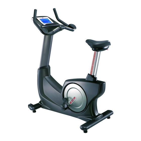
IN 896 Up right bike inSPORTline SEG 7020
Exercise can present a health risk. Consult a
physician before beginning any exercise program
with this equipment.
If you feel faint or dizzy, immediately discontinue use
of this equipment. Serious bodily injury can occur if
this equipment is not assembled and used correctly.
Serious bodily injury can also occur if all instructions
are not followed.
Keep others and pets away from equipment when in
use. Always make sure all bolts and nuts are
tightened prior to each use. Follow all safety
instructions in this manual.
Product May Vary Slightly Different From Picture
Version VIII
MADE IN TAIWAN
Advertisement
Table of Contents

Related Manuals for Insportline 896 SEG 7020


Summary of Contents for Insportline 896 SEG 7020
- Page 1 User manual-EN IN 896 Up right bike inSPORTline SEG 7020 Version VIII Exercise can present a health risk. Consult a physician before beginning any exercise program with this equipment. If you feel faint or dizzy, immediately discontinue use of this equipment. Serious bodily injury can occur if this equipment is not assembled and used correctly.
-
Page 2: Safety Instructions
SAFETY INSTRUCTIONS WARNING: To reduce the risk of serious injury, read the following Safety Instructions before using the Upright Bike. 1. Read all warnings posted on the Upright Bike. 2. Read this Owner's Manual and follow it carefully before using the Upright Bike. Make sure that it is properly assembled and tightened before use. -
Page 3: Upright Bike
BEFORE YOU BEGIN Thank you for choosing the self-powered UPRIGHT Too often, our busy lifestyles limit our time and BIKE. We take great pride in producing this quality opportunity to exercise. The UPRIGHT BIKE provides a product and hope it will provide many hours of quality convenient and simple method to begin your assault on exercise to make you feel better, look better and enjoy getting your body in shape and achieving a happier and... -
Page 4: Hardware Identification Chart
HARDWARE IDENTIFICATION CHART This chart is provided to help identify the hardware used in the assembly process. Place the washers, the end of the bolts, or screws on the circles to check for the correct diameter. Use the small scale to check the length of the bolts and screws. NOTICE: The length of all bolts and screws except those with flat heads is measured from below the head to the end of the bolt or screw. -
Page 5: Assemble Instructions
99 Bolt, Hex Head (M10xp1.5x50mm) ASSEMBLE INSTRUCTIONS Place all parts from the box in a cleared area and position them on the floor in front of you. Remove all packing materials from your area and place them back into the box. Do not dispose of the packing materials until assembly is completed. - Page 6 (M8)(78) and the Bolt, Hex Head (M8xp1.25x65mm)(97) by using socket wrench as the main assembling drawing shows. If the bike is not level, review the LEVELING NOTE on the right side to level the Levelers (27.) ASSEMBLE INSTRUCTIONS STEP 3 Slide the Console Bracket (14) and the Upright Sleeve (18) onto the Upright Post (5.) ...
- Page 7 c. Paste a Logo Sticker on the surface of the Front Decorating Upright Cover (12.) A logo sticker is included in the hardware box. d. Slide the Upright Sleeve (18) down to cover the open area of the Main Frame (1.) ASSEMBLE INSTRUCTIONS STEP 6 ...
- Page 8 STEP 11 Attach the Console Lower Case (15) to the Console (13) and secure with the Screw, Round Head (M5xp0.8x15mm)(83.) ASSEMBLE INSTRUCTIONS STEP 12 Slide the Console Bracket (14) onto the Console (13) and secure with the Screw, Round Head (M5xp0.8x15mm)(83.) STEP 13 a.
-
Page 9: Operational Instructions
Thread the Right Pedal (11) clockwise onto the Right Crank located inside the Right Crank Cover (9) as shown. Tighten the pedal securely. Repeat the same procedure to thread and tighten the Left Pedal (10) counter-clockwise onto the Left Crank as shown. OPERATIONAL INSTRUCTIONS A. -
Page 10: Operational Instruction
OPERATIONAL INSTRUCTION HOW TO INSTALL AND REPLACE BATTERIES: a. Take off the Console Bracket (14): Loosen the Screw, Round Head (M5xp0.8x15mm)(83) at the bottom on the Console Bracket (14.) b. Open the Battery Door (16): Loosen the Screw (M3x10mm)(79) at the bottom on the Console (13) by using the combination wrench to open the Battery Door (16.) c. -
Page 11: Console Overview
CONSOLE OVERVIEW 55% HRC 75% HRC Manual 90% HRC User arget QUICK START CLEAR START / PAUSE RESET PROGRAM DOWN ENTER MODE The console display may vary slightly from the actual console display, the above console overview is for reference only ... -
Page 12: Computer Operation
COMPUTER OPERATION POWER ON: a. Pedaling to activate the console. b. The activated LCD console lights up along with a long beep sound. LCD diagram appears as below: NOTE: Low battery warning signal c. Enter into the initial setting mode after around two seconds as below: Initial Setting Mode POWER OFF: The console would automatically shut off after 30 seconds of inactivity. -
Page 13: Function Buttons
FUNCTION BUTTONS: Button Name Function Description Press the button to select the desired mode – “ , “PROGRAM” , “USER” MANUAL” “TARGET H.R.” as shown: PROGRAM MODE “ENTER” Press the to confirm and enter the function value setting. **The button is equipped with TWO operating methods** , “PROGRAM”... - Page 14 FUNCTION BUTTONS: Button Name Function Description **The button is equipped with TWO operating methods** RESET a. ZEROING FUNCTION: Press the button to reset each function value to zero during setting. The RESET function only operates under PAUSE MODE , “PROGRAM” , “USER”...
-
Page 15: Restart Function
COMPUTER OPERATION MANUAL There are four ways to enter into MANUAL UNDER MODE MODE as below: 1. POWER OFF STATUS (LCD diagram disappear on LCD window): a. Pedaling to activate the console. b. The activated LCD console lights up along with a long beep sound. -
Page 16: Quick Start
COMPUTER OPERATION MANUAL UNDER MODE 3. QUICK START: “MANUAL MODE” “START/PAUSE” “START/PAUSE” button: Press the button directly to start a workout under without any setting. “TIME” , “DISTANCE” , “CALORIES” , Skip to Step C. of NORMAL OPERATION to select the function value of . “PULSE”... - Page 17 COMPUTER OPERATION MANUAL “ENTER” button, the flashing “TIME” will h. After pressing the UNDER MODE appear on the LCD window. “UP” “DOWN” “UP” “DOWN” button: Press the button to the program time as desire. NOTE: The console will cycle through the functions as follow and allow users to set the function values.
- Page 18 COMPUTER OPERATION VERVIEW SETTING VALUES: Display Display Storage Zeroing Description and small tip Readout range “TIME” 0:00 to 1. Time will count up to 99:00 and cycle run the 99:00 program profile without setting. (Use (During a workout. “RESET” The selected value 2.Time will count down to 0 depends on desired button) will turn to zero...
- Page 19 COMPUTER OPERATION PROGRAM There are three ways to enter into PROGRAM UNDER MODE MODE as below: 1. POWER OFF STATUS (LCD diagram disappear on LCD window): a. Pedaling to activate the console. b. The activated LCD console lights up along with a long beep sound.
- Page 20 COMPUTER OPERATION PROGRAM UNDER MODE 3. NORMAL OPERATION: ““START/PAUSE” button: Press the “START/ PAUSE” button to pause the current program. “PROGRAM” “PROGRAM” “PROGRAM “MANUAL” , button: Press the button to select MODE” while in other mode ( “USER” “TARGET H.R.” ). “ENTER”...
- Page 21 Watt Control “ENTER” button, the flashing “TIME” will appear on the LCD window. f. After pressing the “UP” “DOWN” “UP” “DOWN” button: Press the button to select the program time as desire. NOTE: The console will cycle through the functions as follow and allow users to set the function values. TIME (01:00 to 99:00;...
-
Page 22: Program Mode
COMPUTER OPERATION PROGRAM “START/PAUSE” button: To start a workout, press the UNDER MODE “START/PAUSE” button . a. WITHOUT PULSE VALUE: “ ” flashing symbol will appear when detecting your pulse. b. THE WARNING BEEP SOUND EMIT CONSTANLY DURING WORKOUT: If your pulse is greater than the SELECTED PULSE VALUE during workout, the short warning beep sound will constantly emit. - Page 23 COMPUTER OPERATION P12 (WATT CONTROL) UNDER “START/PAUSE” START/PAUSE” button: Press the button PROGRAM MODE to pause the current program. “RESET” “RESET” button: Hold the button FOUR SECONDS to enter into the initial setting mode as the illustration shown on the right. The RESET function only operates under PAUSE MODE “PROGRAM”...
- Page 24 START/PAUSE” button: After setting up all the function values, P12 (WATT CONTROL) UNDER press the START/PAUSE” button to start a workout. PROGRAM MODE Under PAUSE or START mode, the user could press the “UP” “DOWN” button to adjust the desired Watt value (40 ~ 400Watt.) a.
- Page 25 COMPUTER OPERATION USER There are three ways to enter into USER MODE as UNDER MODE below: 1. POWER OFF STATUS (LCD diagram disappear on LCD window): a. Pedaling to activate the console. b. The activated LCD console lights up along with a long beep sound.
- Page 26 COMPUTER OPERATION USER UNDER MODE 3. NORMAL OPERATION: ““START/PAUSE” button: Press the “START/ PAUSE” button to pause the current program. “PROGRAM” “PROGRAM” “USER “MANUAL” , button: Press the button to select MODE” while in other mode ( “PROGRAM” “TARGET H.R.” ) “ENTER”...
-
Page 27: User Mode
COMPUTER OPERATION USER UNDER MODE “START/PAUSE” “START/PAUSE” button: Press the button to start a workout directly without setting function values ( “TIME” , “DISTANCE” , “CALORIES” , “PULSE” .) ENTER Or hold the “ ” button for 3 seconds to continue selecting the other function value of TIME, DISTANCE, CALORIES, PULSE. - Page 28 COMPUTER OPERATION TARGET H.R. There are three ways to enter into TARGET H.R. UNDER MODE as below: MODE 1. POWER OFF STATUS (LCD diagram disappear on LCD window): a. Pedaling to activate the console. b. The activated LCD console lights up along with a long beep sound.
- Page 29 COMPUTER OPERATION TARGET H.R. 3. NORMAL OPERATION: UNDER MODE ““START/PAUSE” button: Press the“START/ PAUSE” button to pause the current program. “TARGET H. R.” “PROGRAM” “PROGRAM” button: Press the button to select as shown. “ENTER” “ENTER” button: Press the button for confirming and entering the function value setting. “PAUSE MODE”...
- Page 30 COMPUTER OPERATION TARGET H.R. “UP” “DOWN” button: If choose THR mode, the function UNDER MODE value of pulse (70 to 240 RPM) will flash on the LCD window. “UP” “DOWN” Press the button to set the desired value for the target heart rate. “ENTER”...
-
Page 31: Warm-Up And Cool-Down
WARM-UP and COOL-DOWN The purpose of warming up is to prepare your body for exercise and to minimize injuries. Warm up for two to Warm-up five minutes before strength-training or aerobic exercising. Perform activities that raise your heart rate and warm the working muscles. -
Page 32: Parts List
PARTS LIST PARTS NAME Q'TY PARTS NAME Q'TY Main Frame Foam Grip (40mm) Front Stabilizer Pulse Sensor Top Housing Rear Stabilizer Pulse Sensor Bottom Housing Seat Post Pulse Sensor Plate Upright Post Generator Handlebar Pulley (120mm) Left Cover Belt (762mm J8) Right Cover Pulley (235mm) Crank Cover... - Page 33 Bolt, Button Head (M6×p1.0×12mm) NO. PARTS NAME Q'TY Axle Connection Cap Bolt, Button Head (M8x35mm) Bolt, Button Head (M8×p1.25×16mm) Bearing 6004ZZ Bolt, Button Head (M10×p1.5×45mm) Idler Wheel Spacer Screw, Flat Head (M8×p1.25×12mm) One Way Pulley (51) Bolt, Socket Head (M8×p1.25×70mm) One Way Bearing (2520) Bolt, Socket Head (M10×p1.5×30mm) Axle...
-
Page 34: Product Parts Drawing
PRODUCT PARTS DRAWING...
Need help?
Do you have a question about the 896 SEG 7020 and is the answer not in the manual?
Questions and answers