Table of Contents
Advertisement
Quick Links
Advertisement
Table of Contents

Subscribe to Our Youtube Channel
Related Manuals for Insportline IN 1823


Summary of Contents for Insportline IN 1823
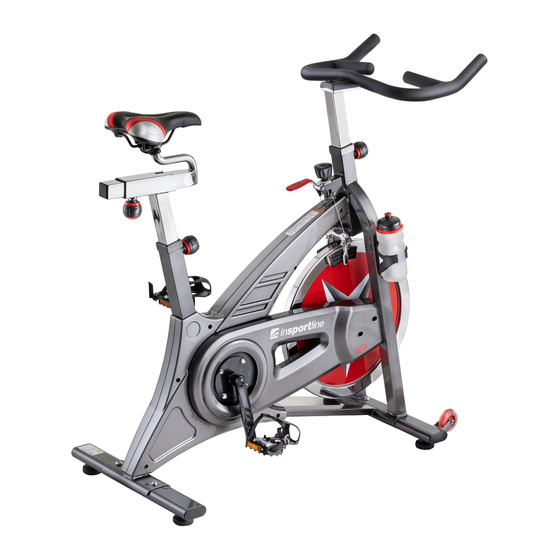
- Page 1 IN 1823 Indoor exercise bike Signa Manual - EN...
-
Page 2: Safety Guideline
SAFETY GUIDELINE 1. Once assemble fully, please inspect to make sure all hardware parts such as bolts, nuts and washers are positioned and in stability situation. 2. Always inspect the safety chain guard that protects the moving parts of the bike to be in safe and in good order. -
Page 3: Exploded Drawing
2. Adjust Seat (22) to a suitable position by adjusting Seat Sliders(3)and Seat Post (2). And please adjust height of Handlebar (4) according to your body size. 3. Set right resistance by Tension Knob (11), please set a right resistance according to your body condition. -
Page 4: Part List
Part list Part No. Series No. DESCRIPTION SPECIFICATION QTY HP-SP0708PK-01-00A Main Frame □38*460*t1.5 0708-03-06A Seat Post □38*270*t1.5 HP-SP0708-03-03A Seat Slider □38*270*1.5T 0708-05-10A Handlebar Post Ø28*998*t1.5 HP-SP0709-05-00A Handlebar HP-SP0708PK-06-09A Tension Bracket Flat Oval HP-SP0708-04-04A Rear Base 30*70*1.5T*498L Flat Oval HP-SP0708-04-00A Front Base 30*70*1.5T*498L SP0708PKS-09-00A Brake-handle... - Page 5 Crank Cover Φ20*Φ10*1.5 Flat Washer Inner Hexagon Flat Round Head Screw M10x25 Right & Left Pedal 9/16"-20UNF-RH Flywheel Flywheel HP-SP0708PK-06-02A Spindle M12*P1.0*166 Belt Ø205*19.8W HP-SP0708PKS-11-06A Wheel Ø18*Ø12*36L HP-SP0708PK- 06-04A Sleeve Pulley, Flywheel φ37*φ30*24.5 HP-SP0810-2PJ-03-07A (front drive) Clamp Brake Brake Pad and HP-SP-0708-06-13A Assembly Brake String...
- Page 6 Hexagon Nut Brake cable Inner Hexagon Flat Round Bolt M6x12 M6x12 Inner Hexagon Flat Round Bolt M10x25 M10x25 Inner Hexagon Flat Round Bolt M10x16 M10x16 Inner Hexagon Flat Round Bolt M6x40 M6x40 Mounting the brake clamp Brake pad Pedal case Pedal buckle Water bottle Holder water...
-
Page 7: Steps Of Installation
INSTALATION: Steps of Installation: Step 1:Assemble Front Base and Rear Base According to the following figure, fix the Front Base (8) and Rear Base (7) to the Main Frame (1) φ20*φ10*1.5T , Flat Washer Hexagonal hollow bolt M10*25L(34) respectively with 4pcs of (33) by Opening Wrench #17 for fastening. - Page 8 Step 2:Assemble Water Bottle Holder and Water Bottle. (72) Please refer to the following figure, fix the Water Bottle Holder to Main Frame (1) via using some (71) (72) tools, and put the Water Bottle into the Water Bottle Holder Step 3:Install Left Pedal and Right one.
- Page 9 Step 4:Assemble the Handlebar Post. According the following figure, slacken the Pop Pin (23), and slide the Handlebar Post (4) into the Handlebar Post Housing on the Main Frame (1), and re-tighten the Pop Pin (23). Step 5:Assemble the Handlebar. Fix the Handlebar (5) to the Handlebar Post and tighten it with Flat WasherΦ10 (33) and Hexagon Flat Round Head Screw M10*25L (34).
-
Page 10: Step 9:Installation Completed
Step 8:Fix Meter Board and Meter. According to the figure as below, firstly, install the control panel (75) to the Handlebar (5) with Phillips screw (76), and then, fix meter (74) onto control panel (75) with Phillips screw (77) by Opening Wrench. Connect the Speed string to Meter finally. - Page 12 !!The system for monitoring heart rate may not be accurate. Overloading during training can to cause a serious injury or death. If you feel unwell, stop exercising!!! NOTICE 1. Inspect all the Nuts, Nut Caps and Pedals in safe situation regularly and inspect the Equipment periodically.
Need help?
Do you have a question about the IN 1823 and is the answer not in the manual?
Questions and answers