Table of Contents
Advertisement
Quick Links
Advertisement
Table of Contents

Subscribe to Our Youtube Channel
Related Manuals for Insportline Ellare YK-B5815


Summary of Contents for Insportline Ellare YK-B5815
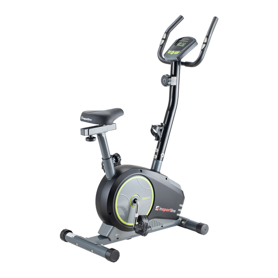
- Page 1 USER MANUAL - EN IN 7558 Magnetic Upright Bike inSPORTline Ellare (YK-B5815)
-
Page 2: Table Of Contents
CONTENTS SAFETY INSTRUCTIONS ........................3 PARTS LIST ............................4 HARDWARE PACKING LIST ........................6 EXPLODED VIEW ........................... 7 ASSEMBLY INSTRUCTIONS ......................... 8 OPERATING THE COMPUTER......................12 MAINTENANCE ............................ 12 TROUBLESHOOTING .......................... 13 WARM UP AND COOL DOWN ROUTINE .................... 13 TERMS AND CONDITIONS OF WARRANTY, WARRANTY CLAIMS .......... -
Page 3: Safety Instructions
IMPORTANT: Read all instructions carefully before using this product. Retain this owner’s manual for future reference. The specifications of this product may vary from this photo, subject to change without notice. SAFETY INSTRUCTIONS Basic precautions should always be followed, including the following safety instructions when using this equipment: Read all instructions before using this equipment. -
Page 4: Parts List
PARTS LIST Description Main Frame Front Stabilizer Rear Stabilizer Idle Wheel Bracket Seat Post Seat Sliding Tube Handlebar Post Handlebar U Bracket Washer Ø16xØ8x1.5 Eyebolt M8x85 End Cap For Front Stabilizer End Cap For Rear Stabilizer Big Curve Washer Ø8 Adjustable Leveler M8 Spring Ø6 Bolt M8x70... - Page 5 Washer Ø24xØ40x3.0 Washer Ø23xØ34.5x2.5 Hexagon Nut 7/8" Belt Pulley with Crank Ø240J6 Bolt M5X45 Big Curve Washer Ø5 Bolt M5X10 Handlebar Foam Grip Ø24xØ30x550 Left Pedal YH-30X Right Pedal YH-30X End Cap for Handlebar Cover Cap Round Knob M16 Hand Pulse Sensor with Wire L=750mm Sensor with Wire L=750mm Left Chain Cover Right Chain Cover...
-
Page 6: Hardware Packing List
HARDWARE PACKING LIST (14) Big Curve Washer Ø8 (17) Bolt M8x70 (30) Cap Nut M8 4 PCS 4 PCS 4 PCS TOOLS Allen Wrench S6 Multi Hex Tool with Phillips Screwdriver 1 PC S10, S13, S14, S15 1 PC... -
Page 7: Exploded View
EXPLODED VIEW... -
Page 8: Assembly Instructions
ASSEMBLY INSTRUCTIONS STEP 1: FRONT AND REAR STABILIZERS INSTALLATION Position the Front Stabilizer (2) in front of the Main Frame (1) and align bolt holes. Attach the Front Stabilizer (2) onto the front curve of the Main Frame (1) with two M8x70 Bolts (17), two Ø8 Big Curve Washers (14), and two M8 Cap Nuts (30). -
Page 9: Seat Post
STEP 2: SEAT POST, SEAT POST COVER, SEAT CUSHION, AND SEAT SLIDING TUBE INSTALLATION Slide the Seat Post Cover (59) onto the tube of the Main Frame (1). Insert the Seat Post (5) into the Seat Post Bushing (53) on the tube of the Main Frame (1) and then attach the Seat Post Knob (48) onto the tube of the Main Frame (1) by turning it in a clockwise direction with Multi Hex Tool provided to lock the Seat Post (5) in the suitable position. -
Page 10: Handlebar Post
STEP 3: HANDLEBAR POST, HANDLEBAR POST COVER, AND TENSION CONTROL KNOB INSTALLATION Remove four M8x15 Bolts (19), four Ø20xØ8x2.0 Washers (14) from the Main Frame (1). Remove bolts with the S6 Allen Wrench provided. Slide the Handlebar Post Cover (58) up to the Handlebar Post (7). Insert the Tension Cable (55) through into the bottom hole of Handlebar Post (7) and pull it out from the square hole of Handlebar Post (7). - Page 11 STEP 4: HANDLEBAR INSTALLATION Insert the Hand Pulse Sensor Wires (49) into the hole on the Handlebar Post (7) and then pull them out from the top end of the Handlebar Post (7). Place the Handlebar (8) through clamp on the Handlebar Post (7) with hand pulse sensors facing the seat.
-
Page 12: Operating The Computer
the Computer (62) onto the top end of the Handlebar Post (7) with four M5x10 Bolts (42) that were removed. Tighten bolts with the Multi Hex Tool with Phillips Screwdriver provided. OPERATING THE COMPUTER SPECIFICATIONS TIME 0:00 - 99:59 MIN:SEC 0.0 –... -
Page 13: Troubleshooting
to prevent screen damage. Please inspect all assembly bolts and pedals on the machine for proper tightness every week. Storage Store the upright bike in a clean and dry environment away from children. TROUBLESHOOTING The upright bike wobbles Turn the adjustable leveler on the rear stabilizer as needed to level the when in use. - Page 14 SHOULDER LIFTS Lift your right shoulder toward your ear for one count. Then lift your left shoulder up for one count as you lower your right shoulder. SIDE STRETCHES Open your arms to the side and lift them until they are over your head. Reach your right arm as far toward the ceiling as you can for one count.
- Page 15 INNER THIGH STRETCH Sit with the soles of your feet together and your knees pointing outward. Pull your feet as close to your groin as possible. Gently push your knees toward the floor. Hold for 15 counts. TOE TOUCHES Slowly bend forward from your waist, letting your back and shoulders relax as you stretch toward your toes.
-
Page 16: Terms And Conditions Of Warranty, Warranty Claims
CALF/ACHILLES STRETCH Lean against a wall with your left leg in front of the right and your arms forward. Keep your right leg straight and the left foot on the floor; then bend the left leg and lean forward by moving your hips toward the wall. - Page 17 The Seller provides the Buyer a 24 months Warranty for Goods Quality, unless otherwise specified in the Certificate of Warranty, Invoice, Bill of Delivery or other documents related to the Goods. The legal warranty period provided to the Consumer is not affected. By the Warranty for Goods Quality, the Seller guarantees that the delivered Goods shall be, for a certain period of time, suitable for regular or contracted use, and that the Goods shall maintain its regular or contracted features.
- Page 18 Date of Sale: Stamp and Signature of Seller:...
Need help?
Do you have a question about the Ellare YK-B5815 and is the answer not in the manual?
Questions and answers