
Related Manuals for Insportline SPORTline SEG 6601


Summary of Contents for Insportline SPORTline SEG 6601
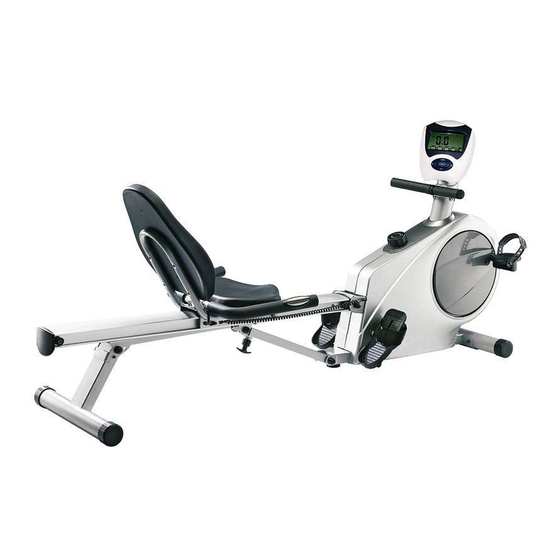
- Page 1 USER MANUAL – EN IN 901 2in1 Rower / Recumbent Bike SPORTline SEG 6601 Product May Vary Slightly From Pictured...
-
Page 2: Table Of Contents
CONTENTS SAFETY INSTRUCTIONS ............................ 3 HARDWARE IDENTIFICATION CHART ......................4 EXPLODED VIEW ..............................6 PARTS LIST ................................7 ASSEMBLY INSTRUCTIONS ..........................10 USING THE ELECTRONIC COMPUTER ......................15 RECUMBENT BIKE MODE / ROWER MODE ....................18 SEAT ADJUSTMENT ............................19 LOAD ADJUSTMENT ............................ -
Page 3: Safety Instructions
CAUTION: Weight on this product should not exceed 250 lbs / 113 kgs. WARNING! Exercise can present a health risk. Consult a physician before beginning any exercise program with this equipment. If you feel faint or dizzy, immediately discontinue use of this equipment. Serious bodily injury can occur if this equipment is not assembled and used correctly. -
Page 4: Hardware Identification Chart
WARNING: Before starting any exercise or conditioning program you should consult with your personal physician to see if you require a complete physical exam. This is especially important if you are over the age of 35, have never exercised before, are pregnant, or suffer from any illness. READ AND FOLLOW THE SAFETY PRECAUTIONS. -
Page 5: Nylock Nut M10X1.5Mm
Bolt, Hex Head M6x1x30mm Bolt, Hex Head M8x1.25x16mm Bolt, Hex Head M10x1.5x85mm Bolt, Hex Head M10x1.5x95mm Bolt, Hex Head M10x1.5x125mm Nylock Nut M8x1.25mm Nylock Nut M10x1.5mm Large Washer M8x23mm Bolt, Button Head M8x12mm Bolt, Round Head M5x0.8x12mm Wrench (17 mm) Allen Wrench(6 mm) Combination Wrench... -
Page 6: Exploded View
EXPLODED VIEW... -
Page 7: Parts List
PARTS LIST PART NAME Main Frame Front Stabilizer Axle Pulley Strap Wheel Connection Wheel One Way Bearing Bearing (6004Z) C Ring M20 Bearing Housing V-Ribbed Belt Idler Arm Idler Wheel Idler Wheel Spacer Tension Spring Magnetic System Bungee Cord Bungee Wheel Wheel Bushing Wheel Spacer Strap... - Page 8 Left Crank Right Cover Flange Bolt M8x1.25x25mm Left Pedal Left Pedal Strap Right Pedal Right Pedal Strap Stand Pedal Shaft Spacer Foot Pedal Pedal Strap Stopper Tube Rail Pivot Pivot Bushing Rail Connection Cap Rail Stopper Stopper Bolt Rail Cap Support Tube Inner Support Tube Bushing...
-
Page 9: Large Washer
Pulse Coil Wire Pulse Connection Wire Moving Wheel Round Endcap 60mm Round Plug 25mm Nut Cap M10 Carriage Bolt M8x1.25x60mm Carriage Bolt M8x1.25x70mm Screw, Round Head M4x20mm Screw, Round Head M4x25mm Screw, Round Head M5x18mm Screw, Round Head M5x0.8x15mm Screw, Round Head M5x0.8x18mm Bolt, Socket Head M5x0.8x15mm Bolt, Round Head M6x1x15mm Bolt, Round Head M6x1x30mm... -
Page 10: Assembly Instructions
Bolt, Button Head M8x12mm Screw, Round Head M5x0.8x12mm Wrench 17mm Allen Wrench 6mm Combination Wrench User Manual ASSEMBLY INSTRUCTIONS Place all parts from the box in a cleared area and position them on the floor in front of you. Remove all packing materials from your area and place them back into the box. - Page 11 onto the left end. Secure the FOOT PEDALS with BUTTON HEAD BOLTS (M8x15mm)(94) and LARGE WASHERS (M8)(109) at both ends of the PEDAL SHAFT (44). NOTE: You need to use two Allen Wrenches to tighten the BUTTON HEAD BOLTS (M8x15mm)(94) at both ends of the PEDAL SHAFT (44) at the same time.
- Page 12 Release NOTE: Be careful not to damage the PULSE SENSOR WIRES (73, 74) while doing assembly STEP 8 to STEP STEP 8: Attach the HANDRAIL (70) onto the SEAT CARRIAGE (64) with BUTTON HEAD BOLTS (M8x12mm)(114). STEP 9: Attach the SEAT (68) onto the SEAT CARRIAGE (64) with ROUND BOLTS (M6x15mm)(95). Attach the BACK CUSHION (69) onto the SEAT CARRIAGE (64) with ROUND BOLTS (M6x30mm)(96).
- Page 13 NOTE: The RIGHT PEDAL (41) has R stamped on the end of the pedal shaft. The RIGHT PEDAL (41) has right hand threads and is tightened by turning clockwise. The LEFT PEDAL (39) has L stamped on the end of the pedal shaft.
- Page 14 STEP 13: Insert the SENSOR WIRE (29) and PULSE CONNECTION WIRE (75) into the bottom end of METER POST (31) and pull them out of the top of the METER POST (31). Pull the HANDLEBAR (25), twist the STRAP (21) and slide the strap thru the gap into the hole in the bottom of the METER POST (31).
-
Page 15: Using The Electronic Computer
USING THE ELECTRONIC COMPUTER KEY GUIDE ENTER 1. Select function to be preset. (RESET) Gender-Height-Weight-Age-Time-Distance-Calorie-Pulse 2. Press this button to enter setting mode. 3. Press this button to confirm the setting values. 4. Hold two seconds to reset all of the values to zero. 5. - Page 16 3. If the display appears blank or display only partial segment, remove the batteries and wait 15 seconds, then replace. 4. Whenever remove batteries, all the functions values will be reset to zero. 5. The batteries must be removed from the appliance before it is scrapped and that they are disposed of safely.
- Page 17 you want. Count up: Without setting the calorie value, the monitor will count up the calorie from 0.1~999.0. Count down: Setting the exercise calorie from 1.0~999.0, the monitor will count down from your setting values. Once reach setting value, monitor will alarm. Press the button of UP or DOWN until the dot of pulse display on the screen.
-
Page 18: Recumbent Bike Mode / Rower Mode
show your value. The value will show on the screen from 1 ~ 9999 Kcal. C. BMI: Body Mass Index: The monitor will calculate the data of height and weight to show your value. The value will show on the screen from 1.0 ~ 99.9 on screen. D. -
Page 19: Seat Adjustment
SEAT ADJUSTMENT Proper seat adjustment is important for Recumbent Bike mode. 1. Sit on the seat and place your feet on the pedals. You should be able to move through a complete pedal stroke without locking your knees or shifting your hips on the seat. The seat is too close to the pedals if you have more than a slight bend in your knees at the bottom of the pedal stroke. -
Page 20: Storage
5. Worn or damaged components shall be replaced immediately or the 2 in 1 Rower / Recumbent Bike removed from service until repair is made. 6. Keep your 2 in 1 Rower / Recumbent Bike clean by wiping with an absorbent cloth after use. STORAGE 1. -
Page 21: Terms And Conditions Of Warranty, Warranty Claims
TERMS AND CONDITIONS OF WARRANTY, WARRANTY CLAIMS General Conditions of Warranty and Definition of Terms All Warranty Conditions stated hereunder determine Warranty Coverage and Warranty Claim Procedure. Conditions of Warranty and Warranty Claims are governed by Act No. 40/1964 Coll. Civil Code, Act No. 513/1991 Coll., Commercial Code, and Act No. - Page 22 +420 556 770 190, Mobile: +420 604 853 019, servis@insportline.cz Fax: +420 556 770 192, (Service +420 556 770 191) Web: www.insportline.cz, www.worker.cz, www.worker-moto.cz INSPORTLINE, s.r.o. Bratislavska 36, 911 05 Trencin, Slovakia CRN: 36311723, VAT ID: SK2020177082 Orders: +421(0)326 526 701, +421(0)917 649 192, objednavky@insportline.sk...
Need help?
Do you have a question about the SPORTline SEG 6601 and is the answer not in the manual?
Questions and answers