
Related Manuals for EWM Tetrix 180 Smart TGD


Summary of Contents for EWM Tetrix 180 Smart TGD
- Page 1 Operating instructions Welding machine Tetrix 180 Smart TGD 099-000124-EW501 29.07.2011 Register now! For your benefit Jetzt Registrieren und Profitieren! www.ewm-group.com...
-
Page 2: General Instructions
© EWM HIGHTEC WELDING GmbH · Dr. Günter-Henle-Str. 8 · D-56271 Mündersbach, Germany The copyright to this document remains the property of the manufacturer. -
Page 3: Table Of Contents
Contents Notes on the use of these operating instructions Contents 1 Contents..............................3 2 Safety instructions..........................6 Notes on the use of these operating instructions ................6 Explanation of icons........................7 General ............................8 Transport and installation ......................12 Ambient conditions........................13 2.5.1 In operation........................ - Page 4 Resetting welding parameters to the factory settings ..............67 Display machine control software version..................68 8 Technical data............................69 Tetrix 180 Smart...........................69 9 Accessories ............................70 Remote controls and accessories....................70 Options ............................70 Transportsysteme ........................70 General accessories ........................70 Computer communication ......................70 10 Appendix A............................71 10.1 Overview of EWM branches......................71 099-000124-EW501 29.07.2011...
- Page 5 Contents Notes on the use of these operating instructions 099-000124-EW501 29.07.2011...
-
Page 6: Safety Instructions
Safety instructions Notes on the use of these operating instructions Safety instructions Notes on the use of these operating instructions DANGER Working or operating procedures which must be closely observed to prevent imminent serious and even fatal injuries. • Safety notes include the "DANGER" keyword in the heading with a general warning symbol. •... -
Page 7: Explanation Of Icons
Safety instructions Explanation of icons Explanation of icons Symbol Description Press Do not press Turn Switch Switch off machine Switch on machine ENTER (enter the menu) NAVIGATION (Navigating in the menu) EXIT (Exit the menu) Time display (example: wait 4s/press) Interruption in the menu display (other setting options possible) Tool not required/do not use Tool required/use... -
Page 8: General
Safety instructions General General DANGER Electromagnetic fields! The power source may cause electrical or electromagnetic fields to be produced which could affect the correct functioning of electronic equipment such as IT or CNC devices, telecommunication lines, power cables, signal lines and pacemakers. •... - Page 9 Safety instructions General WARNING Smoke and gases! Smoke and gases can lead to breathing difficulties and poisoning. In addition, solvent vapour (chlorinated hydrocarbon) may be converted into poisonous phosgene due to the ultraviolet radiation of the arc! • Ensure that there is sufficient fresh air! •...
- Page 10 Safety instructions General CAUTION Damage due to the use of non-genuine parts! The manufacturer's warranty becomes void if non-genuine parts are used! • Only use system components and options (power sources, welding torches, electrode holders, remote controls, spare parts and replacement parts, etc.) from our range of products! •...
- Page 11 Safety instructions General CAUTION EMC Machine Classification In accordance with IEC 60974-10, welding machines are grouped in two electromagnetic compatibility classes (see technical data): Class A machines are not intended for use in residential areas where the power supply comes from the low-voltage public mains network.
-
Page 12: Transport And Installation
Safety instructions Transport and installation Transport and installation WARNING Incorrect handling of shielding gas cylinders! Incorrect handling of shielding gas cylinders can result in serious and even fatal injury. • Observe the instructions from the gas manufacturer and in any relevant regulations concerning the use of compressed air! •... -
Page 13: Ambient Conditions
Safety instructions Ambient conditions Ambient conditions CAUTION Installation site! The machine must not be operated in the open air and must only be set up and operated on a suitable, stable and level base! • The operator must ensure that the ground is non-slip and level, and provide sufficient lighting for the place of work. -
Page 14: Intended Use
Intended use Applications Intended use This machine has been manufactured according to the latest developments in technology and current regulations and standards. It must only be operated in line with the instructions on correct usage. WARNING Hazards due to improper usage! Hazards may arise for persons, animals and material objects if the equipment is not used correctly. -
Page 15: Documents Which Also Apply
Intended use Documents which also apply Documents which also apply 3.2.1 Warranty NOTE For further information, please see the accompanying supplementary sheets "Machine and Company Data, Maintenance and Testing, Warranty"! 3.2.2 Declaration of Conformity The designated machine conforms to EC Directives and standards in terms of its design and construction: •... -
Page 16: Machine Description
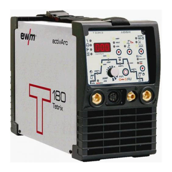
Machine description Front view Machine description Front view Figure 4-1 Item Symbol Description Carrying strap Machine control See Machine control – operating elements chapter Connection socket, “+” welding current Connection for workpiece lead Connection socket, 5-pole/8-pole 5-pole: Standard TIG torch control lead 8-pole: TIG Up/Down or potentiometer torch control lead G¼”... -
Page 17: Rear View
Machine description Rear view Rear view Figure 4-2 Item Symbol Description Main switch, machine on/off Ignition type changeover switch Liftarc (contact ignition) HF ignition PC interface, serial (D-Sub connection socket, 9-pole) G¼” connecting nipple Shielding gas connection on the pressure regulator Connection socket, 19-pole Remote control connection Mains connection cable... -
Page 18: Machine Control - Operating Elements
Machine description Machine control – Operating elements Machine control – Operating elements Figure 4-3 Item Symbol Description Error/status indicators Collective interference signal light Water deficiency signal light (welding torch cooling) Excess temperature signal light safety sign signal light Three-figure LED display Welding parameter display (see also chap. - Page 19 Machine description Machine control – Operating elements Item Symbol Description Down-slope time (TIG) 0.00 s to 20.0 s (0.1 s increments). The down-slope time can be set separately for non-latched and latched. Gas post-flow time (TIG) Setting ranges: 0.00 sec to 40.0 sec (0.1 sec increments). Select welding parameters button This button is used to select the welding parameters depending on the welding process and operating mode used.
-
Page 20: Design And Function
Design and function General Design and function General WARNING Risk of injury from electric shock! Contact with live parts, e.g. welding current sockets, is potentially fatal! • Follow safety instructions on the opening pages of the operating instructions. • Commissioning may only be carried out by persons who have the relevant expertise of working with arc welding machines! •... -
Page 21: Transport And Installation
Design and function Transport and installation Transport and installation WARNING Risk of accident due to improper transport of machines that may not be lifted! Do not lift or suspend the machine! The machine can fall down and cause injuries! The handles and brackets are suitable for transport by hand only! •... -
Page 22: Mains Connection
Design and function Mains connection Mains connection DANGER Hazard caused by improper mains connection! An improper mains connection can cause injuries or damage property! • Only use machine with a plug socket that has a correctly fitted protective conductor. • If a mains plug must be fitted, this may only be carried out by an electrician in accordance with the relevant national provisions or regulations (any phase sequence for three-phase machines)! -
Page 23: Tig Welding
Design and function TIG welding TIG welding 5.6.1 Welding torch and workpiece line connection NOTE Prepare welding torch according to the welding task in hand (see operating instructions for the torch). Figure 5-3 Item Symbol Description Welding torch Welding torch hose package Connection socket, "-"... -
Page 24: Torch Connection Options And Pin Assignments
Design and function TIG welding 5.6.2 Torch connection options and pin assignments Down Uref 10V Uref 10V IH-Down Poti UD/ein Poti UD/ein Figure 5-4 5.6.3 Shielding gas supply (shielding gas cylinder for welding machine) WARNING Incorrect handling of shielding gas cylinders! Incorrect handling of shielding gas cylinders can result in serious and even fatal injury. -
Page 25: Connecting The Shielding Gas Supply
Design and function TIG welding 5.6.3.1 Connecting the shielding gas supply • Place the shielding gas cylinder into the relevant cylinder bracket. • Secure the shielding gas cylinder using a securing chain. Figure 5-5 Item Symbol Description Pressure regulator Shielding gas cylinder Output side of the pressure regulator Cylinder valve NOTE... -
Page 26: Setting The Shielding Gas Quantity
Design and function TIG welding 5.6.3.2 Setting the shielding gas quantity CAUTION Electric shocks! When setting the shielding gas quantity, high voltage ignition pulses or open circuit voltage are applied at the welding torch; these can lead to electric shocks and burning on contact. -
Page 27: Select Welding Task
Design and function TIG welding 5.6.4 Select welding task NOTE No changes can be made to the basic welding parameters during the welding process. The welding task is selected using the buttons on the machine control on the welding machine. Signal lights (LED) display the welding parameter selection. -
Page 28: Arc Ignition
Design and function TIG welding 5.6.6 Arc ignition 5.6.6.1 HF ignition Figure 5-7 The arc is started without contact from high-voltage ignition pulses. a) Position the welding torch in welding position over the workpiece (distance between the electrode tip and workpiece should be approx. 2-3mm). b) Press the torch trigger (high voltage ignition pulses ignite the arc). -
Page 29: Function Sequences/Operating Modes
Design and function TIG welding 5.6.8 Function sequences/operating modes The parameters for the function sequence are set using the “Select welding parameters” button and the “Welding parameter setting” rotary dial. Figure 5-9 Item Symbol Description Select welding parameters button This button is used to select the welding parameters depending on the welding process and operating mode used. -
Page 30: Non-Latched Mode
Design and function TIG welding 5.6.8.2 Non-latched mode Figure 5-10 1st cycle: • Press and hold torch trigger 1. • The gas pre-flow time elapses. • HF ignition pulses jump from the electrode to the workpiece, the arc ignites. • The welding current flows and immediately assumes the value set for the ignition current I start •... -
Page 31: Latched Mode
Design and function TIG welding 5.6.8.3 Latched mode AMP% start Down Figure 5-11 Step 1 • Press torch trigger 1, the gas pre-flow time elapses. • HF ignition pulses jump from the electrode to the workpiece, the arc ignites. • Welding current flows and immediately assumes the ignition current value set (search arc at minimum setting). -
Page 32: Spotarc
Design and function TIG welding 5.6.8.4 SpotArc The TIG SpotArc function is activated with the pulse variant automated frequencies by default, because this combination produces the most effective results. Selecting and setting TIG spotArc Operating Action Result element Signal light comes on The spot time can be set for approx. -
Page 33: Spotmatic
Design and function TIG welding 5.6.8.5 Spotmatic The arc is ignited fully automatically without actuating the torch trigger by simply touching the tip of the electrode with the workpiece. Hundreds of reproducible tacks can be made without tungsten inclusions. NOTE Selection and adjustment are made in the same way as with spotArc operating mode (see chapter TIG spotArc). -
Page 34: Non-Latched Operation, Version C
Design and function TIG welding 5.6.8.6 Non-latched operation, version C Figure 5-14 1st cycle • Press torch trigger 1, the gas pre-flow time elapses. • HF ignition pulses jump from the electrode to the workpiece, the arc ignites. • Welding current flows and immediately adopts the ignition current value set (search arc at minimum setting). -
Page 35: Automated Pulses
Design and function TIG welding 5.6.8.7 Automated pulses NOTE The machines have an integrated pulse device. With pulses, the machine switches back and forth between the pulse current (main current) and pause current (secondary current). The automated pulses are used with tacking and spot welding of workpieces in particular. An oscillation in the molten pool is produced by the current-dependent pulse frequency and balance, which positively influences the ability to bridge the air gap. -
Page 36: Tig Activarc Welding
5.6.9 TIG activArc welding The EWM activArc process, thanks to the highly dynamic controller system, ensures that the power supplied is kept virtually constant in the event of changes in the distance between the welding torch and the weld pool, e.g. during manual welding. Voltage losses as a result of a shortening of the distance between the torch and molten pool are compensated by a current rise (ampere per volt - A/V), and vice versa. -
Page 37: Welding Torch (Operating Variants)
Design and function TIG welding 5.6.10 Welding torch (operating variants) Different torch versions can be used with this machine. Functions on the operating elements, such as torch triggers (TT), rockers or potentiometers, can be modified individually via torch modes. Explanation of symbols for operating elements: Symbol Description Press torch trigger... -
Page 38: 5.6.11 Torch Mode And Up/Down Speed Setting
Design and function TIG welding 5.6.11 Torch mode and up/down speed setting The user has the modes 1 to 6 and modes 11 to 16 available. Modes 11 to 16 include the same function options as 1 to 6, but without tapping function for the secondary current. The function options in the individual modes can be found in the tables for the corresponding torch types. -
Page 39: Standard Tig Torch (5-Pole)
Design and function TIG welding 5.6.11.1 Standard TIG torch (5-pole) Standard torch with one torch trigger: Diagram Operating Explanation of symbols elements BRT1 = Torch trigger 1 (welding current on/off; secondary current via tapping function) Functions mode Operating elements BRT 1 Welding current On/Off (factory-set) BRT 1... - Page 40 Design and function TIG welding Standard torch with one rocker (MG rocker, two torch triggers) Diagram Operating Explanation of symbols elements BRT 1 = torch trigger 1 BRT 2 = torch trigger 2 Functions mode Operating elements BRT 1 Welding current On/Off Secondary current BRT 2 (factory-set)
-
Page 41: Tig Up/Down Torch (8-Pole)
Design and function TIG welding 5.6.11.2 TIG up/down torch (8-pole) Up/down torch with one torch trigger Diagram Operating Explanation of symbols elements TT 1 = torch trigger 1 Functions Mode Operating elements BRT 1 Welding current on/off BRT 1 Secondary current (tapping mode) / (Latched mode) (factory- set) Increase welding current, infinite adjustment (up function) - Page 42 Design and function TIG welding Up/down torch with two torch triggers Diagram Operating Explanation of symbols elements TT 1 = torch trigger 1 (left) TT 2 = torch trigger 2 (right) Functions Mode Operating elements BRT 1 Welding current on/off BRT 2 Secondary current BRT 1...
-
Page 43: Potentiometer Torch (8-Pole)
Design and function TIG welding 5.6.11.3 Potentiometer torch (8-pole) NOTE The welding machine needs to be configured for operation with a potentiometer torch (see chap. "Configuring TIG potentiometer torch") Potentiometer torch with one torch trigger: Diagram Operating Explanation of symbols elements BRT 1 = torch trigger 1 Functions... -
Page 44: 5.6.12 Setting The First Increment
Design and function TIG welding 5.6.12 Setting the first increment Figure 5-17 Figure 5-18 Display Setting/selection Exit the menu Exit Torch configuration menu Set welding torch functions Setting the first increment Setting: 1 to 20 (factory setting 1) NOTE This function is only available when using up/down torches in modes 4 and 14! 099-000124-EW501 29.07.2011... -
Page 45: Mma Welding
Design and function MMA welding MMA welding CAUTION Risk of being crushed or burnt. When replacing spent or new stick electrodes • Switch off machine at the main switch • Wear appropriate safety gloves • Use insulated tongs to remove spent stick electrodes or to move welded workpieces and •... -
Page 46: Select Welding Task
Design and function MMA welding 5.7.2 Select welding task Operating Action Result element Select MMA welding process signal light lights up in green Set welding current 5.7.3 Hotstart current and Hotstart time The hotstart device improves the ignition of the stick electrodes using an increased ignition current. a) = Hotstart time b) = Hotstart current Welding current... -
Page 47: Arcforce
Design and function MMA welding 5.7.4 Arcforce Shortly before the electrode threatens to stick, the arcforcing device sets an increased current designed to prevent the electrode sticking. Operating Action Result Displays element Select arcforcing welding parameter signal light lights up in red Set arcforcing = low current increase >... -
Page 48: Remote Control
Design and function Remote control Remote control NOTE The remote control is operated on the 19-pole remote control connection socket. 5.8.1 Manual remote control RT 1 Functions • Infinitely adjustable welding current (0% to 100%) depending on the preselected main current on the welding machine. 5.8.2 RTG1 19POL manual remote control Functions... -
Page 49: Foot-Operated Remote Control Rtf 1
Design and function Remote control 5.8.6 Foot-operated remote control RTF 1 Functions • Infinitely adjustable welding current (0% to 100%) depending on the preselected main current on the welding machine. • Start/stop welding operation (TIG) ActivArc welding is not possible in combination with the RTF 1 foot-operated remote control. FFr >... -
Page 50: Interfaces For Automation
Design and function Interfaces for automation Interfaces for automation CAUTION Damage to the machine due to improper connection! Unsuitable control leads or incorrect connection of input and output signals can cause damage to the machine. • Only use shielded control leads! •... -
Page 51: Pc Interface
Design and function PC interface 5.10 PC interface CAUTION Equipment damage or faults may occur if the PC is connected incorrectly! Not using the SECINT X10USB interface results in equipment damage or faults in signal transmission. The PC may be destroyed due to high frequency ignition pulses. •... -
Page 52: Advanced Settings
Design and function Advanced settings 5.11 Advanced settings 5.11.1 Setting slope times for secondary current AMP% or pulse edges Figure 5-23 Figure 5-24 Display Setting/selection Expert menu Slope time tS1 (main current to secondary current) Setting: 0.00 s to 20.0 s (factory setting 0.01 s) Slope time tS2 (secondary current to main current) Setting: 0.00 s to 20.0 s (factory setting 0.01 s) 099-000124-EW501... -
Page 53: 5.11.2 Tig Non-Latched Operating Mode, C Version
Design and function Advanced settings 5.11.2 TIG non-latched operating mode, C version Figure 5-25 Display Setting/selection Exit the menu Exit Machine configuration Settings for machine functions and parameter display Non-latched operation (C version) • on = on • off = off (factory setting) 099-000124-EW501 29.07.2011... -
Page 54: 5.11.3 Configuring The Tig Potentiometer Torch Connection
Design and function Advanced settings 5.11.3 Configuring the TIG potentiometer torch connection DANGER Risk of injury due to electrical voltage after switching off! Working on an open machine can lead to fatal injuries! Capacitors are loaded with electrical voltage during operation. Voltage remains present for up to two minutes after the mains plug is removed. -
Page 55: Welding Current Display (Ignition, Secondary, End And Hotstart Currents)
Design and function Advanced settings 5.11.4 Welding current display (ignition, secondary, end and hotstart currents) The welding currents for secondary current, ignition current and end current (expert menu) can be displayed as percentages (factory setting) or absolute values on the machine display. Figure 5-27 Display Setting/selection... -
Page 56: Ramp Function Foot-Operated Remote Control Rtf 1
Design and function Advanced settings 5.11.5 Ramp function foot-operated remote control RTF 1 Figure 5-28 Display Setting/selection Exit the menu Exit Machine configuration Settings for machine functions and parameter display Ramp function Remote control RTF 1 The ramp function can be switched on and off Switch on Switching on machine function Switch off... -
Page 57: Menus And Sub-Menus On The Machine Control
Design and function Menus and sub-menus on the machine control 5.12 Menus and sub-menus on the machine control 5.12.1 Direct menus (direct access to parameters) Functions, parameters and their values can be accessed directly, e.g. can be selected by pressing a button once. -
Page 58: Expert Menu (Tig)
Design and function Menus and sub-menus on the machine control 5.12.3 Expert menu (TIG) The expert menu includes functions and parameters which are either not set on the machine control, or which do not require regular setting. Figure 5-30 Display Setting/selection Expert menu Gas pre-flow time... -
Page 59: 5.12.4 Machine Configuration Menu
Design and function Menus and sub-menus on the machine control 5.12.4 Machine configuration menu Figure 5-31 NOTE ENTER (enter the menu) • Switch off machine at the main switch • Press and hold the "welding parameters" button and switch the machine on again at the same time. - Page 60 Design and function Menus and sub-menus on the machine control Display Setting/selection Exit the menu Exit Torch configuration menu Set welding torch functions Torch mode • Modes 1-6: with tapping function (factory setting 1) • Modes 11-16: without tapping function Setting the first increment Setting: 1 to 20 (factory setting 1) Up-/Down speed (not available in modes 4 and 14)
- Page 61 Design and function Menus and sub-menus on the machine control Display Setting/selection Orbital welding Correction value for orbital current Service menu Modifications to the service menu may only be carried out by authorised maintenance staff! Reset (reset to factory settings) •...
-
Page 62: Maintenance, Care And Disposal
Maintenance, care and disposal General Maintenance, care and disposal DANGER Risk of injury from electric shock! Cleaning machines that are not disconnected from the mains can lead to serious injuries! • Disconnect the machine completely from the mains. • Remove the mains plug! •... -
Page 63: Maintenance Work
Information about giving back used equipment or about collections can be obtained from the respective municipal administration office. • EWM participates in an approved waste disposal and recycling system and is registered in the Used Electrical Equipment Register (EAR) under number WEEE DE 57686922. •... -
Page 64: Rectifying Faults
Rectifying faults Customer checklist Rectifying faults All products are subject to rigorous production checks and final checks. If, despite this, something fails to work at any time, please check the product using the following flowchart. If none of the fault rectification procedures described leads to the correct functioning of the product, please inform your authorised dealer. - Page 65 Rectifying faults Customer checklist Unstable arc Material inclusions in the tungsten electrode due to contact with filler material or workpiece Regrind or replace the tungsten electrode Incompatible parameter settings Check settings and correct if necessary Pore formation Inadequate or missing gas shielding Check shielding gas setting and replace shielding gas cylinder if necessary Shield welding site with protective screens (draughts affect the welding result) Use gas diffuser for aluminium applications and high-alloy steels...
-
Page 66: Error Messages (Power Source)
Rectifying faults Error messages (power source) Error messages (power source) NOTE A welding machine error is indicated by the collective fault signal lamp (A1) lighting up and an error code (see table) being displayed in the machine control display. In the event of a machine error, the power unit shuts down. -
Page 67: Resetting Welding Parameters To The Factory Settings
Rectifying faults Resetting welding parameters to the factory settings Resetting welding parameters to the factory settings NOTE All customised welding parameters that are stored will be replaced by the factory settings. Figure 7-1 Display Setting/selection Exit the menu Exit Service menu Modifications to the service menu may only be carried out by authorised maintenance staff! Reset (reset to factory settings) -
Page 68: Display Machine Control Software Version
Rectifying faults Display machine control software version Display machine control software version NOTE The query of the software versions only serves to inform the authorised service staff! Figure 7-2 Display Setting/selection Exit the menu Exit Service menu Modifications to the service menu may only be carried out by authorised maintenance staff! Software version query (example) System bus ID... -
Page 69: Technical Data
Technical data Tetrix 180 Smart Technical data Tetrix 180 Smart NOTE Performance specifications and guarantee only in connection with original spare and replacement parts! Welding current setting range 5A-180 A 10A-150 A Welding voltage setting range 10.2 V-17.2 V 20.2 V-26.0 V Duty cycle at 25 °C 35% DC 180 A... -
Page 70: Accessories
Accessories Remote controls and accessories Accessories NOTE Performance-dependent accessories like torches, workpiece leads, electrode holders or intermediate hose packages are available from your authorised dealer. Remote controls and accessories Type Designation Item no. RTF1 19POLE 5M Foot-operated remote control current with 094-006680-00000 connection cable Remote control current... -
Page 71: Overview Of Ewm Branches
Appendix A Overview of EWM branches Appendix A 10.1 Overview of EWM branches 099-000124-EW501 29.07.2011...
Need help?
Do you have a question about the Tetrix 180 Smart TGD and is the answer not in the manual?
Questions and answers