
Related Manuals for EWM Picomig 185 Synergic TKG


Summary of Contents for EWM Picomig 185 Synergic TKG
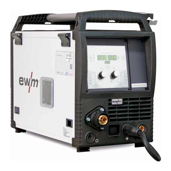
- Page 1 Operating instructions Welding machine Picomig 185 Synergic TKG 099-005548-EW501 27.10.2017...
- Page 2 +49 2680 181-0. A list of authorised sales partners can be found at www.ewm-group.com. Liability relating to the operation of this equipment is restricted solely to the function of the equipment.
-
Page 3: Table Of Contents
Contents Notes on the use of these operating instructions Contents 1 Contents ..............................3 2 For your safety ............................5 Notes on the use of these operating instructions ................5 Explanation of icons ........................6 Part of the complete documentation ....................7 Safety instructions .......................... - Page 4 Resetting welding parameters to the factory settings ..............56 Display machine control software version ..................56 Dynamic power adjustment ......................56 8 Technical data............................57 Picomig 185 Synergic TKG ......................57 9 Accessories ............................58 General accessories ........................58 Options ............................58 Transport systems ........................
-
Page 5: For Your Safety
For your safety Notes on the use of these operating instructions For your safety Notes on the use of these operating instructions DANGER Working or operating procedures which must be closely observed to prevent imminent serious and even fatal injuries. •... -
Page 6: Explanation Of Icons
For your safety Explanation of icons Explanation of icons Symbol Description Symbol Description Indicates technical aspects which the Activate and release/tap/tip user must observe. Switch off machine Release Switch on machine Press and keep pressed Switch Wrong Turn Numerical value – adjustable Correct Menu entry Signal light lights up in green... -
Page 7: Part Of The Complete Documentation
For your safety Part of the complete documentation Part of the complete documentation These operating instructions are part of the complete documentation and valid only in combination with all other parts of these instructions! Read and observe the operating instructions for all system components, especially the safety instructions! The illustration shows a general example of a welding system. - Page 8 For your safety Safety instructions WARNING Risk of injury from electrical voltage! Voltages can cause potentially fatal electric shocks and burns on contact. Even low voltages can cause a shock and lead to accidents. • Never touch live components such as welding current sockets or stick, tungsten or wire electrodes! •...
- Page 9 For your safety Safety instructions WARNING Fire hazard! Due to the high temperatures, sparks, glowing parts and hot slag that occur during welding, there is a risk of flames. • Be watchful of potential sources of fire in the working area! •...
- Page 10 For your safety Safety instructions CAUTION Electromagnetic fields! The power source may cause electrical or electromagnetic fields to be produced which could affect the correct functioning of electronic equipment such as IT or CNC devices, telecommunication lines, power cables, signal lines and pacemakers. •...
-
Page 11: Transport And Installation
For your safety Transport and installation Transport and installation WARNING Risk of injury due to improper handling of shielding gas cylinders! Improper handling and insufficient securing of shielding gas cylinders can cause serious injuries! • Observe the instructions from the gas manufacturer and any relevant regulations concerning the use of compressed air! •... -
Page 12: Intended Use
3.2.1 Warranty For more information refer to the "Warranty registration" brochure supplied and our information regarding warranty, maintenance and testing at www.ewm-group.com! 3.2.2 Declaration of Conformity The labelled machine complies with the following EC directives in terms of its design and construction: •... -
Page 13: Machine Description - Quick Overview
Machine description – quick overview Front view Machine description – quick overview Front view Figure 4-1 Item Symbol Description Transport bar Protective cap Cover for the wire feed mechanism and other operating elements. Depending on the machine series, additional stickers with information on the replacement parts and JOB lists will be located on the inside. -
Page 14: Rear View
Machine description – quick overview Rear view Item Symbol Description Connection socket, "+" welding current • ---------- MIG/MAG cored wire welding: Workpiece connection • ---------- TIG welding: Workpiece connection • ---------- MMA welding: Workpiece connection Cooling air inlet Machine control > see 4.4 chapter Carrying handle Rear view Figure 4-2... -
Page 15: Inside View
Machine description – quick overview Inside view Inside view Figure 4-3 Item Symbol Description Sticker, JOB List > see 11.1 chapter Push-button, wire inching Potential- and gas-free inching of the wire electrode through the hose package to the welding torch > see 5.3.2.4 chapter. Wire spool holder Wire feed unit 099-005548-EW501... -
Page 16: Machine Control - Operating Elements
Machine description – quick overview Machine control – Operating elements Machine control – Operating elements The setting ranges for the parameter values are summarised in the Parameter overview section > see 12.1 chapter. Figure 4-4 Item Symbol Description “Collective interference” signal light “Excess temperature”... - Page 17 Machine description – quick overview Machine control – Operating elements Item Symbol Description Welding task push-button (JOB) JOB- LIST Select the welding task from the welding task list (JOB-LIST). The list can be found inside the protective cap on the wire feeder and in the appendix to these operating instructions.
-
Page 18: Design And Function
Design and function Transport and installation Design and function WARNING Risk of injury from electrical voltage! Contact with live parts, e.g. power connections, can be fatal! • Observe the safety information on the first pages of the operating instructions! • Commissioning must be carried out by persons who are specifically trained in handling power sources! •... -
Page 19: Workpiece Lead, General
Design and function Transport and installation 5.1.3 Workpiece lead, general CAUTION Risk of burning due to incorrect welding current connection! If the welding current plugs (machine connections) are not locked or if the workpiece connection is contaminated (paint, corrosion), these connections and leads can heat up and cause burns when touched! •... -
Page 20: Notes On The Installation Of Welding Current Leads
Design and function Transport and installation 5.1.5 Notes on the installation of welding current leads Incorrectly installed welding current leads can cause faults in the arc (flickering). Lay the workpiece lead and hose package of power sources without HF igniter (MIG/MAG) for as long and as close as possible in parallel. -
Page 21: Stray Welding Currents
Design and function Transport and installation 5.1.5.1 Stray welding currents WARNING Risk of injury due to stray welding currents! Stray welding currents can destroy protective earth conductors, damage machines and electronic devices and cause overheating of components, leading to fire. •... -
Page 22: Mains Configuration
Design and function Transport and installation 5.1.6.1 Mains configuration The machine may only be connected to a one-phase system with two conductors and an earthed neutral conductor. Figure 5-6 Legend Item Designation Colour code Outer conductor brown Neutral conductor blue Protective conductor green-yellow •... -
Page 23: Shielding Gas Hose Connection
Design and function Transport and installation Item Symbol Description Output side of the pressure regulator Cylinder valve • Before connecting the pressure regulator to the gas cylinder, open the cylinder valve briefly to blow out any dirt. • Tighten the pressure regulator screw connection on the gas bottle valve to be gas-tight. •... -
Page 24: Gas Test - Setting The Shielding Gas Volume
Design and function Transport and installation Gas test – setting the shielding gas volume 5.1.7.3 If the shielding gas setting is too low or too high, this can introduce air to the weld pool and may cause pores to form. Adjust the shielding gas quantity to suit the welding task! •... -
Page 25: Welding Data Display
Design and function Welding data display Welding data display Figure 5-9 The push-button for the welding parameter display mode is next to the display. Each time the push-button is pressed the display changes to the next parameter. After the last parameter is reached the display continues with the first parameter. - Page 26 Design and function MIG/MAG welding Depending on the wire electrode diameter or type, either a steel liner or liner with the correct inner diameter must be inserted in the torch! Recommendation: • Use a steel liner when welding hard, unalloyed wire electrodes (steel). •...
-
Page 27: Wire Feed
Design and function MIG/MAG welding Item Symbol Description Workpiece "-" welding current connection socket • ----------- MIG/MAG welding: Workpiece connection Polarity selector plug, welding current cable Internal welding current cable for central connection/welding torch. • ----------- Connection socket for “+” welding current •... - Page 28 Design and function MIG/MAG welding Standard D300 wire spool holder can be used. Adapters are required when using standardised basket coils (DIN 8559) > see 9 chapter. Figure 5-11 Item Symbol Description Carrier pin For fixing the wire spool Knurled nut For fixing the wire spool •...
-
Page 29: Changing The Wire Feed Rollers
Design and function MIG/MAG welding 5.3.2.3 Changing the wire feed rollers Figure 5-12 Item Symbol Description Tommy The tommy is used to secure the closure brackets of the wire feed rollers. Closure bracket The closure brackets are used to secure the wire feed rollers. Feed roll tensioner Fixing the clamping unit and setting the pressure. - Page 30 Design and function MIG/MAG welding Unsatisfactory welding results due to faulty wire feeding! The wire feed rolls must be suitable for the diameter of the wire and the material. The wire feed rolls are colour-coded to facilitate distinction (see the Wire feed roll overview table). When working with a wire diameter of >...
-
Page 31: Inching The Wire Electrode
Design and function MIG/MAG welding 5.3.2.4 Inching the wire electrode CAUTION Risk of injury due to welding wire escaping from the welding torch! The welding wire can escape from the welding torch at high speed and cause bodily injury including injuries to the face and eyes! •... -
Page 32: Spool Brake Setting
Design and function MIG/MAG welding Incorrect contact pressure will cause extensive wear of the wire feed rollers! • With the adjusting nuts of the pressure units set the contact pressure so that the wire electrode is conveyed but will still slip through if the wire spool jams. •... -
Page 33: Welding Task Selection
Design and function MIG/MAG welding Pay attention to the signal light for the polarity setting! It may be necessary to change the welding current polarity depending on the JOB selected or the welding process. • Reconnect the polarity selction plug if necessary. 5.3.4 Welding task selection The settings for the respective welding parameters are defined by the different JOBs. -
Page 34: Operating Point Setting Using Material Thickness
Design and function MIG/MAG welding 5.3.5.2 Operating point setting using material thickness Automatic display mode switching: If the wire speed or the voltage is changed, the display will switch briefly to show the respective parameter. This means that you don't have to change the display mode before setting the parameter. -
Page 35: Operating Modes (Functional Sequences)
Design and function MIG/MAG welding Display Setting/selection Burn-back correction 5.3.7 Operating modes (functional sequences) 5.3.7.1 Explanation of signs and functions Symbol Meaning Press torch trigger Release torch trigger Shielding gas flowing Welding output Wire electrode is being conveyed Wire creep Wire burn-back Gas pre-flows Gas post-flows... - Page 36 Design and function MIG/MAG welding Non-latched mode Figure 5-21 Step 1 • Press and hold torch trigger. • Shielding gas is expelled (gas pre-flows). • Wire feed motor runs at “creep speed”. • Arc ignites after the wire electrode makes contact with the workpiece; welding current flows. •...
- Page 37 Design and function MIG/MAG welding Latched mode Figure 5-22 1. cycle • Press and hold torch trigger • Shielding gas is expelled (gas pre-flows) • Wire feed motor runs at “creep speed” • Arc ignites when the wire electrode makes contact with the workpiece Welding current flows •...
- Page 38 Design and function MIG/MAG welding Spot welding Figure 5-23 Start • Press and hold torch trigger. • Shielding gas is expelled (gas pre-flows). • Arc ignites after the wire electrode makes contact with the workpiece at creep speed. • Welding current flows. •...
-
Page 39: Conventional Mig/Mag Welding (Gmaw Non Synergic)
Design and function MIG/MAG welding Interval Figure 5-24 Start • Press and hold torch trigger. • Shielding gas is expelled (gas pre-flows). Sequence • Arc ignites after the wire electrode makes contact with the workpiece at creep speed. • Welding current flows. •... -
Page 40: Mig/Mag Automatic Cut-Out
Design and function MMA welding 5.3.9 MIG/MAG automatic cut-out The welding machine ends the ignition process or the welding process with an • Ignition fault (no welding current flows within 5 s after the start signal). • Arc interruption (arc is intrerupted for longer than 3 s). MMA welding CAUTION Risk of crushing and burns! -
Page 41: Welding Task Selection
Design and function MMA welding 5.4.2 Welding task selection • Select MMA JOB 128 > see 11.1 chapter. You can only change the JOB number when no welding current is flowing. Figure 5-27 5.4.3 Arcforce During the welding process, arcforce prevents the electrode sticking in the weld pool with increases in current. -
Page 42: Hotstart Settings
Design and function MMA welding 5.4.4.1 Hotstart settings The setting ranges for the parameter values are summarised in the Parameter overview section > see 12.1 chapter. • Select MMA JOB 128 > see 5.4.2 chapter. ENTER NAVIGATION EXIT Figure 5-30 Display Setting/selection Hotstart current... -
Page 43: Tig Welding
Design and function TIG welding TIG welding 5.5.1 Preparing the TIG welding torch The TIG welding torch is to be equipped to suit the relevant welding task! • Fit suitable tungsten electrodes and • an appropriate shielding gas nozzle. • Observe the operating instructions for the TIG welding torch! 5.5.2 Welding torch and workpiece line connection... -
Page 44: Welding Task Selection
Design and function TIG welding 5.5.3 Welding task selection • Select TIG JOB 127 > see 11.1 chapter. You can only change the JOB number when no welding current is flowing. Figure 5-33 5.5.4 Adjusting the gas post-flow time • Preselection: Select TIG JOB 127 >... -
Page 45: Further Welding Parameters
Design and function TIG welding 5.5.5 Further welding parameters The setting ranges for the parameter values are summarised in the Parameter overview section > see 12.1 chapter. • Preselection: Select TIG JOB 127 > see 5.5.3 chapter. NAVIGATION EXIT ENTER Figure 5-35 Display Setting/selection... -
Page 46: Tig Arc Ignition
Design and function TIG welding 5.5.6 TIG arc ignition 5.5.6.1 Liftarc Figure 5-36 The arc is ignited on contact with the workpiece: a) Carefully place the torch gas nozzle and tungsten electrode tip onto the workpiece and press the torch trigger (liftarc current flowing, regardless of the main current set). - Page 47 Design and function TIG welding Non-latched mode Figure 5-37 1st cycle • Press and hold torch trigger. • Shielding gas is expelled (gas pre-flows). The arc is ignited using liftarc. • The welding current flows with the value set for the starting current I start •...
-
Page 48: Tig Automatic Cut-Out
Design and function TIG welding Latched mode Figure 5-38 1st cycle • Press and hold torch trigger. • Shielding gas is expelled (gas pre-flows). The arc is ignited using liftarc. • The welding current flows with the value set for the starting current I start 2nd cycle •... -
Page 49: Machine Configuration Menu
Design and function Machine configuration menu Machine configuration menu 5.6.1 Selecting, changing and saving parameters NAVIGATION ENTER EXIT Figure 5-39 Display Setting/selection Calibration The machine will be calibrated for approx 2 seconds each time it is switched on. Exit the menu Exit Machine configuration Settings for machine functions and parameter display... -
Page 50: Power-Saving Mode (Standby)
Design and function Power-saving mode (Standby) Power-saving mode (Standby) You can activate the power-saving mode by either pressing the push-button > see 4.4 chapter for a prolonged time or by setting a parameter in the machine configuration menu (time-controlled power- saving mode ) >... -
Page 51: Maintenance, Care And Disposal
Maintenance, care and disposal General Maintenance, care and disposal General DANGER Risk of injury due to electrical voltage after switching off! Working on an open machine can lead to fatal injuries! Capacitors are loaded with electrical voltage during operation. Voltage remains present for up to four minutes after the mains plug is removed. -
Page 52: Maintenance Work, Intervals
A periodic test according to IEC 60974-4 "Periodic inspection and test" has to be carried out. In addition to the regulations on testing given here, the relevant local laws and regulations must also be observed. For more information refer to the "Warranty registration" brochure supplied and our information regarding warranty, maintenance and testing at www.ewm-group.com! 099-005548-EW501 27.10.2017... -
Page 53: Disposing Of Equipment
• Information about returning used equipment or about collections can be obtained from the respective municipal administration office. • In addition to this, returns are also possible throughout Europe via EWM sales partners. 099-005548-EW501 27.10.2017... -
Page 54: Rectifying Faults
Rectifying faults Checklist for rectifying faults Rectifying faults All products are subject to rigorous production checks and final checks. If, despite this, something fails to work at any time, please check the product using the following flowchart. If none of the fault rectification procedures described leads to the correct functioning of the product, please inform your authorised dealer. -
Page 55: Error Messages (Power Source)
Rectifying faults Error messages (power source) Error messages (power source) A welding machine error is indicated by the collective fault signal lamp (A1) lighting up and an error code (see table) being displayed in the machine control display. In the event of a machine error, the power unit shuts down. -
Page 56: Resetting Welding Parameters To The Factory Settings
Rectifying faults Resetting welding parameters to the factory settings Resetting welding parameters to the factory settings RESET Figure 7-1 Display Setting/selection Calibration The machine will be calibrated for approx 2 seconds each time it is switched on. Initialising Keep the push-button pressed until "InI" is shown on the display. Display machine control software version The query of the software versions only serves to inform the authorised service staff. -
Page 57: Technical Data
Technical data Picomig 185 Synergic TKG Technical data Picomig 185 Synergic TKG Performance specifications and guarantee only in connection with original spare and replacement parts! Setting range MIG/MAG Welding current 5 A to180 A 5 A to 150 A Welding voltage 14.3 V to 23 V... -
Page 58: Accessories
Accessories General accessories Accessories Performance-dependent accessories like torches, workpiece leads, electrode holders or intermediate hose packages are available from your authorised dealer. General accessories Type Designation Item no. Mod. 842 Ar/CO2 230bar 15l Pressure regulator with manometer 394-002910-00015 G1 G1/4 R 3M Gas hose 094-000010-00003 Sharpener for plastic liners... -
Page 59: Replaceable Parts
Replaceable parts Wire feed rollers Replaceable parts Performance specifications and guarantee only in connection with original spare and replacement parts! 10.1 Wire feed rollers 10.1.1 Wire feed rollers for steel wire Type Designation Item no. FE 4R 0.6 MM/0.023 INCH Drive roll set, 37 mm, 4 rolls, V-groove for steel, 092-002770-00006 LIGHT PINK... -
Page 60: 10.1.3 Wire Feed Rollers For Cored Wire
Replaceable parts Wire feed rollers 10.1.3 Wire feed rollers for cored wire Type Designation Item no. FUEL 4R 0.8 MM/0.03 INCH Drive roll set, 37 mm, 4 rolls, V-groove/knurled for 092-002848-00008 WHITE/ORANGE flux cored wire FUEL 4R 1.0 MM/0.04 INCH Drive roll set, 37 mm, 4 rolls, V-groove/knurled for 092-002848-00010 BLUE/ORANGE... -
Page 61: Job-List
Appendix A JOB-List Appendix A 11.1 JOB-List We recommend using the characteristics for 1.0-mm solid wire electrodes also for the 0.9-mm solid wire electrodes. Figure 11-1 099-005548-EW501 27.10.2017... -
Page 62: Parameter Overview - Setting Ranges
Appendix B Parameter overview – setting ranges Appendix B Parameter overview – setting ranges 12.1 Parameters/function Setting range MIG/MAG Gas pre-flow time 20,0 Dynamic correction Gas post-flow time 20,0 Spot time 20,0 Pause time (interval) 20,0 Wire burn-back Gas pre-flow time Ignition current Up-slope time 20,0... -
Page 63: Overview Of Ewm Branches
Appendix C Overview of EWM branches Appendix C 13.1 Overview of EWM branches 099-005548-EW501 27.10.2017...
Need help?
Do you have a question about the Picomig 185 Synergic TKG and is the answer not in the manual?
Questions and answers