EWM Pico 300 cel pws Operating Instructions Manual
Hide thumbs
Also See for Pico 300 cel pws:
- Operating instructions manual (44 pages) ,
- Operating instructions manual (52 pages) ,
- Operating instructions manual (41 pages)

Related Manuals for EWM Pico 300 cel pws


Summary of Contents for EWM Pico 300 cel pws
- Page 1 Operating instructions Welding machine Pico 300 cel pws Pico 300 cel pws vrd 12V Pico 300 cel pws svrd 12V 099-002044-EW501 Observe additional system documents! 14.10.2022...
- Page 2 +49 2680 181-0. A list of authorised sales partners can be found at www.ewm-group.com/en/specialist-dealers. Liability relating to the operation of this equipment is restricted solely to the function of the equipment. No other f orm of liability, regardless of type, shall be accepted.
-
Page 3: Table Of Contents
Contents Notes on using these operating instructions Contents 1 Contents........................3 2 For your safety......................6 Notes on using these operating instructions ............... 6 Explanation of icons ....................7 Saf ety instructions ....................8 Transport and installation ..................11 3 Intended use ........................13 Applications......................13 Overview of device types..................13 3.2.1... - Page 4 7 Rectifying faults ......................37 Error messages (power source)................37 Resetting welding parameters to the factory settings ..........38 8 Technical data ......................39 Pico 300 cel pws ....................39 9 Accessories.........................40 Welding torch, electrode holder and workpiece lead ...........40 19-pole remote control ...................40 9.2.1 Connection cables ...................40...
- Page 5 Contents Notes on using these operating instructions 099-002044-EW501 14.10.2022...
-
Page 6: For Your Safety
For your safety Notes on using these operating instructions For your safety Notes on using these operating instructions DANGER Working or operating procedures which must be closely observed to prevent imminent serious and even fatal injuries. • Saf ety notes include the "DANGER" keyword in the heading with a general warning symbol. •... -
Page 7: Explanation Of Icons
For your safety Explanation of icons Explanation of icons Symbol Description Symbol Description Indicates technical aspects which the Activate and release / Tap / Tip user must observe. Switch off machine Release Switch on machine Press and hold Incorrect / Invalid Switch Correct / Valid Turn... -
Page 8: Safety Instructions
For your safety Saf ety instructions Safety instructions WARNING Risk of accidents due to non-compliance with the safety instructions! Non-compliance with the safety instructions can be fatal! • Caref ully read the safety instructions in this manual! • Observe the accident prevention regulations and any regional regulations! •... - Page 9 For your safety Saf ety instructions WARNING Risk of injury due to improper clothing! During arc welding, radiation, heat and voltage are sources of risk that cannot be avoided. The user has to be equipped with the complete personal protective equipment at all times.
- Page 10 For your safety Saf ety instructions CAUTION Smoke and gases! Smoke and gases can lead to breathing difficulties and poisoning. In addition, solvent vapour (chlorinated hydrocarbon) may be converted into poisonous phosgene due to the ultraviolet radiation of the arc! •...
-
Page 11: Transport And Installation
For your safety Transport and installation CAUTION Obligations of the operator! The respective national directives and laws must be complied with when operating the machine! • Implementation of national legislation relating to framework directive 89/391/EEC on the int- roduction of measures to encourage improvements in the safety and health of workers at work and associated individual guidelines. - Page 12 For your safety Transport and installation CAUTION Risk of accidents due to supply lines! During transport, attached supply lines (mains leads, control cables, etc.) can cause risks, e.g. by causing connected machines to tip over and injure persons! • Disconnect all supply lines before transport! Risk of tipping! There is a risk of the machine tipping over and injuring persons or being damaged itself during movement and set up.
-
Page 13: Intended Use
Intended use Applications Intended use WARNING Hazards due to improper usage! The machine has been constructed to the state of the art and any regulations and stand- ards applicable for use in industry and trade. It may only be used for the welding proce- dures indicated at the rating plate. -
Page 14: Documents Which Also Apply
3.3.1 Warranty For more information refer to the "Warranty registration" brochure supplied and our information regarding warranty, maintenance and testing at www.ewm-group.com! 3.3.2 Declaration of Conformity This product corresponds in its design and construction to the EU directives listed in the decla- ration. -
Page 15: Part Of The Complete Documentation
Intended use Documents which also apply 3.3.6 Part of the complete documentation This document is part of the complete documentation and valid only in combination with all other parts of these instructions! Read and observe the operating instructions for all system components, especially the safety instructions! The illustration shows a general example of a welding system. -
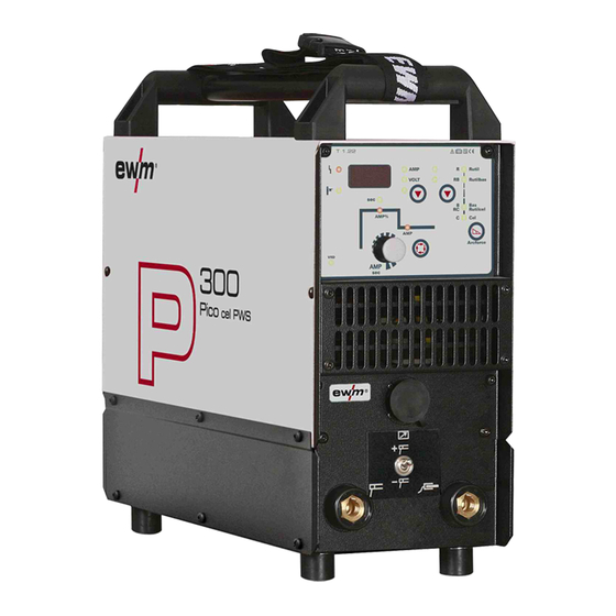
Page 16: Machine Description - Quick Overview
Machine description – quick overview Front view / rear view Machine description – quick overview Front view / rear view Figure 4-1 099-002044-EW501 14.10.2022... - Page 17 Machine description – quick overview Front view / rear view Item Symbol Description Carrying strap > see 5.1.4.1 chapter Carrying handle Machine control > see 4.2 chapter Cooling air inlet Connection socket, 19-pole Remote control connection Welding current polarity switch > see 5.2.2.2 chapter Switch f or quick switching of welding current polarity.
-
Page 18: Machine Control - Operating Elements
Machine description – quick overview Machine control – Operating elements Machine control – Operating elements The parameters and their setting ranges are described in chapter Parameters Overview - Setting Ran- ges > see 10.1 chapter. Figure 4-2 Item Symbol Description Welding data display (3-digit) Displays the welding parameters and the corresponding values >... -
Page 19: Welding Data Display
Machine description – quick overview Machine control – Operating elements Item Symbol Description Switch display button AMP ----- Welding current display VOLT ---- Welding voltage display 4.2.1 Welding data display All relevant welding parameters with their values are shown depending o n the welding procedure selected and the associated functions. -
Page 20: Design And Function
Design and function Transport and installation Design and function Transport and installation WARNING Risk of accident due to improper transport of machines that must not be lifted! Do not lift or suspend the machine! The machine can drop and cause injuries! The handles, straps or brackets are suitable for transport by hand only! •... -
Page 21: Ambient Conditions
Design and function Transport and installation 5.1.3 Ambient conditions The machine must not be operated in the open air and must only be set up and operated on a suitable, stable and level base! • The operator must ensure that the ground is non-slip and level, and provide sufficient lighting for the place of work. -
Page 22: Notes On The Installation Of Welding Current Leads
Design and function Transport and installation 5.1.5 Notes on the installation of welding current leads • Incorrectly installed welding current leads can cause faults in the arc (flickering). • Lay the workpiece lead and hose package of power sources without HF igniter (MIG/MAG) for as long and as close as possible in parallel. -
Page 23: Stray Welding Currents
Design and function Transport and installation 5.1.6 Stray welding currents WARNING Risk of injury due to stray welding currents! Stray welding currents can destroy protective earth conductors, damage machines and electronic devices and cause overheating of components, leading to fire. •... -
Page 24: Mains Connection
Design and function Transport and installation 5.1.7 Mains connection DANGER Hazards caused by improper mains connection! An improper mains connection can cause injuries or damage property! • The connection (mains plug or cable), the repair or voltage adjustment of the device must be carried out by a qualified electrician in accordance with the respective local laws or nati- onal regulations! •... -
Page 25: Mma Welding
Design and function MMA welding MMA welding 5.2.1 Connecting the electrode holder and workpiece lead CAUTION Risk of crushing and burns! When changing stick electrodes there is a risk of crushing and burns! • Wear appropriate and dry protective gloves. •... -
Page 26: Welding Task Selection
Design and function MMA welding 5.2.2 Welding task selection Figure 5-8 5.2.2.1 Arcforce (welding characteristics) During the welding process, arcforce prevents the electrode sticking in the weld pool with increases in current. This makes it easier to weld large-drop melting electrode types at low current strengths with a short arc in particular. -
Page 27: Hotstart
Design and function MMA welding 5.2.3 Hotstart The f unction hot start ensures a secure igniting of the arc and a sufficient heating to the still cold parent metal at the beginning of the welding process. The ignition takes place here with increased current (hot start current) over a certain time (hot start time). -
Page 28: Tig Welding
Design and function TIG welding TIG welding 5.3.1 Shielding gas supply (shielding gas cylinder for welding machine) WARNING Risk of injury due to improper handling of shielding gas cylinders! Improper handling and insufficient securing of shielding gas cylinders can cause seri- ous injuries! •... -
Page 29: Connecting A Tig Welding Torch With Rotating Gas Valve
Design and function TIG welding 5.3.2 Connecting a TIG welding torch with rotating gas valve Prepare welding torch according to the welding task in hand (see operating instructions for the torch). Figure 5-15 Item Symbol Description Output side of the pressure regulator Welding torch Workpiece •... -
Page 30: Welding Task Selection
Design and function Remote control 5.3.3 Welding task selection Figure 5-16 With the selection the TIG welding process, the function of the welding current polarity changeover switch is deactivated. The welding current polarity is permanently set to "-" on the electrode holder connection socket. -
Page 31: Rtf1 19Pol
Design and function Dirt f ilter 5.4.2 RTF1 19POL Features • Inf initely adjustable welding current (0% to 100%) depending on the preselected main current on the welding machine. 5.4.3 RT PWS1 19POL When a remote control is connected, the polarity is changed at the changeover switch of the remote control (ex works). -
Page 32: Voltage Reducing Device
Design and function Voltage reducing device Voltage reducing device Only machine variants with the (VRD/SVRD/AUS/RU) code are equipped with a voltage reduction device (VRD). The VRD is used for increased safety, especially in hazardous environments such as shipbuilding, pipe construction or mining. A VRD is mandatory in some countries and required by many on-site safety instructions for power sources. -
Page 33: Welding Current Actual Value Display
Design and function Machine configuration menu 5.7.3 Welding current actual value display The welding current in the welding data display is displayed as nominal value at the factory. The welding current display can be determined by switching the parameter to actual values in the respective ex- pert menu: MMA welding TIG welding... -
Page 34: Maintenance, Care And Disposal
Maintenance, care and disposal General Maintenance, care and disposal General DANGER Risk of injury due to electrical voltage after switching off! Working on an open machine can lead to fatal injuries! Capacitors are loaded with electrical voltage during operation. Voltage remains present for up to four minutes after the mains plug is removed. -
Page 35: Maintenance Work, Intervals
A periodic test according to IEC 60974-4 "Periodic inspection and test" has to be carried out. In addition to the regulations on testing given here, the relevant local laws and regulations must also be observed. For more information refer to the "Warranty registration" brochure supplied and our information regarding warranty, maintenance and testing at www.ewm-group.com! 099-002044-EW501 14.10.2022... -
Page 36: Disposing Of Equipment
Inf ormation on returning used equipment or collections can be obtained from the respective municipal administration office. Devices can also be returned to EWM sales partners across Europe. Further inf ormation on the topic of the disposal of electrical and electronic equipment can be found on our website at: https://www.ewm-group.com/de/nachhaltigkeit.html. -
Page 37: Rectifying Faults
Rectifying faults Error messages (power source) Rectifying faults All products are subject to rigorous production checks and final checks. If , despite this, something fails to work at any time, please check the product using the following flowchart. If none of the fault rectification procedures described leads to the correct functioning of the product, please inform your authorised dea- ler. -
Page 38: Resetting Welding Parameters To The Factory Settings
Rectifying faults Resetting welding parameters to the factory settings Resetting welding parameters to the factory settings All customised welding parameters that are stored will be replaced by the factory settings. RESET Figure 7-1 Display Setting/selection Calibration The machine will be calibrated for approx 2 seconds each time it is switched on. Initialising Keep the push-button pressed until is shown on the display. -
Page 39: Technical Data
Technical data Pico 300 cel pws Technical data Performance specifications and guarantee only in connection with original spare and replacement parts! Pico 300 cel pws Welding current (I 10 A to 300 A Welding voltage according to standard (U 20,4 V to 32,0 V 10,4 V to 22,0 V Duty cycle DC at 40°... -
Page 40: Accessories
Accessories Welding torch, electrode holder and workpiece lead Accessories Welding torch, electrode holder and workpiece lead Type Designation Item no. EH50 4M Electrode holder 092-000004-00000 WK50QMM 4M KL Workpiece cable, clamp 092-000003-00000 TIG 26V 4M ABITIG 26 V 4 m BCC-1 BHC-01 094-010979-00000 19-pole remote control Type... -
Page 41: Appendix
Appendix Parameter overview – setting ranges Appendix 10.1 Parameter overview – setting ranges Parameters/function Setting range MMA (MMA) Main current (AMP) Hot start current (AMP%) Hot start time (sec) 20,0 Arcf orce correction Arc length restriction of f of f Welding current actual value display of f of f... -
Page 42: 10.2 Searching For A Dealer
Appendix Searching for a dealer 10.2 Searching for a dealer Sales & service partners www.ewm-group.com/en/specialist-dealers "More than 400 EWM sales partners worldwide" 099-002044-EW501 14.10.2022...
Need help?
Do you have a question about the Pico 300 cel pws and is the answer not in the manual?
Questions and answers