
Related Manuals for EWM Pico 300 cel


Summary of Contents for EWM Pico 300 cel
- Page 1 Operating instructions Welding machine Pico 300 cel Pico 300 cel vrd 12V Pico 300 cel svrd 12V 099-002032-EW501 Observe additional system documents! 15.10.2018...
-
Page 2: General Instructions
+49 2680 181-0. A list of authorised sales partners can be found at www.ewm-group.com/en/specialist-dealers. Liability relating to the operation of this equipment is restricted solely to the function of the equipment. No other form of liability, regardless of type, shall be accepted. -
Page 3: Table Of Contents
Contents Notes on the use of these operating instructions Contents 1 Contents ..............................3 2 For your safety ............................6 Notes on the use of these operating instructions ................6 Explanation of icons ........................7 Part of the complete documentation ....................8 Safety instructions .......................... - Page 4 Error messages (power source) ....................36 Resetting welding parameters to the factory settings ..............37 8 Technical data............................38 Pico 300 cel ..........................38 9 Accessories ............................39 Welding torch, electrode holder and workpiece lead ..............39 Remote controls and accessories ....................39 Options ............................
- Page 5 Contents Notes on the use of these operating instructions 099-002032-EW501 15.10.2018...
-
Page 6: For Your Safety
For your safety Notes on the use of these operating instructions For your safety Notes on the use of these operating instructions DANGER Working or operating procedures which must be closely observed to prevent imminent serious and even fatal injuries. •... -
Page 7: Explanation Of Icons
For your safety Explanation of icons Explanation of icons Symbol Description Symbol Description Indicates technical aspects which the Activate and release / Tap / Tip user must observe. Switch off machine Release Switch on machine Press and hold Switch Incorrect / Invalid Turn Numerical value –... -
Page 8: Part Of The Complete Documentation
For your safety Part of the complete documentation Part of the complete documentation These operating instructions are part of the complete documentation and valid only in combination with all other parts of these instructions! Read and observe the operating instructions for all system components, especially the safety instructions! The illustration shows a general example of a welding system. -
Page 9: Safety Instructions
For your safety Safety instructions Safety instructions WARNING Risk of accidents due to non-compliance with the safety instructions! Non-compliance with the safety instructions can be fatal! • Carefully read the safety instructions in this manual! • Observe the accident prevention regulations and any regional regulations! •... - Page 10 For your safety Safety instructions WARNING Explosion risk! Apparently harmless substances in closed containers may generate excessive pressure when heated. • Move containers with inflammable or explosive liquids away from the working area! • Never heat explosive liquids, dusts or gases by welding or cutting! Fire hazard! Due to the high temperatures, sparks, glowing parts and hot slag that occur during welding, there is a risk of flames.
- Page 11 For your safety Safety instructions CAUTION According to IEC 60974-10, welding machines are divided into two classes of electromagnetic compatibility (the EMC class can be found in the Technical data) > see 8 chapter: Class A machines are not intended for use in residential areas where the power supply comes from the low-voltage public mains network.
- Page 12 For your safety Safety instructions The manufacturer's warranty becomes void if non-genuine parts are used! • Only use system components and options (power sources, welding torches, electrode holders, remote controls, spare parts and replacement parts, etc.) from our range of products! •...
-
Page 13: Transport And Installation
For your safety Transport and installation Transport and installation WARNING Risk of injury due to improper handling of shielding gas cylinders! Improper handling and insufficient securing of shielding gas cylinders can cause serious injuries! • Observe the instructions from the gas manufacturer and any relevant regulations concerning the use of compressed air! •... -
Page 14: Intended Use
Intended use Overview of device types Intended use WARNING Hazards due to improper usage! The machine has been constructed to the state of the art and any regulations and standards applicable for use in industry and trade. It may only be used for the welding procedures indicated at the rating plate. -
Page 15: Documents Which Also Apply
3.3.1 Warranty For more information refer to the "Warranty registration" brochure supplied and our information regarding warranty, maintenance and testing at www.ewm-group.com! 3.3.2 Declaration of Conformity The labelled product complies with the following EC directives in terms of its design and construction: •... -
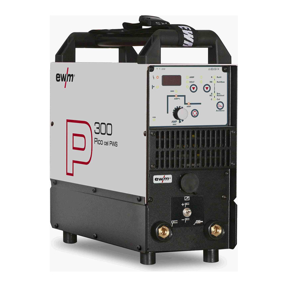
Page 16: Machine Description - Quick Overview
Machine description – quick overview Front view / rear view Machine description – quick overview Front view / rear view Figure 4-1 099-002032-EW501 15.10.2018... - Page 17 Machine description – quick overview Front view / rear view Item Symbol Description Carrying strap > see 5.1.4 chapter Carrying handle Machine control > see 4.2 chapter Cooling air inlet Connection socket, “-” welding current • MMA: Connection of electrode holder or workpiece lead •...
-
Page 18: Machine Control - Operating Elements
Machine description – quick overview Machine control – Operating elements Machine control – Operating elements Figure 4-2 Item Symbol Description Welding data display (3-digit) Displays the welding parameters and the corresponding values > see 4.2.1 chapter Collective interference signal light For error messages, >... -
Page 19: Welding Data Display
Machine description – quick overview Machine control – Operating elements 4.2.1 Welding data display All relevant welding parameters with their values are shown depending on the welding procedure selected and the associated functions. Machine parameters and error codes are shown as well in a unique manner. -
Page 20: Design And Function
Design and function Transport and installation Design and function Transport and installation WARNING Risk of accident due to improper transport of machines that must not be lifted! Do not lift or suspend the machine! The machine can drop and cause injuries! The handles, straps or brackets are suitable for transport by hand only! •... -
Page 21: In Operation
Design and function Transport and installation 5.1.3.1 In operation Temperature range of the ambient air: • -25 °C to +40 °C (-13 °F to 104 °F) Relative humidity: • up to 50 % at 40 °C (104 °F) • up to 90 % at 20 °C (68 °F) 5.1.3.2 Transport and storage Storage in a closed room, temperature range of the ambient air:... - Page 22 Design and function Transport and installation Figure 5-2 Use an individual welding lead to the workpiece for each welding machine! Figure 5-3 Fully unroll welding current leads, torch hose packages and intermediate hose packages. Avoid loops! Always keep leads as short as possible! Lay any excess cable lengths in meanders.
-
Page 23: Stray Welding Currents
Design and function Transport and installation 5.1.6 Stray welding currents WARNING Risk of injury due to stray welding currents! Stray welding currents can destroy protective earth conductors, damage machines and electronic devices and cause overheating of components, leading to fire. •... -
Page 24: Mains Configuration
Design and function Transport and installation 5.1.7.1 Mains configuration The machine may be connected to: • a three-phase system with four conductors and an earthed neutral conductor • a three-phase system with three conductors of which any one can be earthed, e.g. -
Page 25: Mma Welding
Design and function MMA welding MMA welding CAUTION Risk of crushing and burns! When changing stick electrodes there is a risk of crushing and burns! • Wear appropriate and dry protective gloves. • Use an insulated pair of tongs to remove the used stick electrode or to move welded workpieces. -
Page 26: Welding Task Selection
Design and function MMA welding • Insert cable plug of the electrode holder into either the "+" or "-" welding current connection socket and lock by turning to the right. • Insert cable plug of the workpiece lead into either the "+" or "-" welding current connection socket and lock by turning to the right. -
Page 27: Hotstart Time
Design and function MMA welding 5.2.3.1 Hotstart time EXIT AMP% Figure 5-11 5.2.3.2 Hotstart current EXIT AMP% Figure 5-12 5.2.4 Antistick The Antistick feature prevents the electrode from annealing. Should the electrode stick despite the Arcforce feature, the machine automatically switches to the minimum current within approx. one second. -
Page 28: Tig Welding
Design and function TIG welding TIG welding 5.3.1 Shielding gas supply (shielding gas cylinder for welding machine) WARNING Risk of injury due to improper handling of shielding gas cylinders! Improper handling and insufficient securing of shielding gas cylinders can cause serious injuries! •... -
Page 29: Connecting A Tig Welding Torch With Rotating Gas Valve
Design and function TIG welding 5.3.3 Connecting a TIG welding torch with rotating gas valve Prepare welding torch according to the welding task in hand (see operating instructions for the torch). Figure 5-15 Item Symbol Description Workpiece Welding torch Output side of the pressure regulator •... -
Page 30: Gas Test - Setting The Shielding Gas Volume
Design and function Remote control Gas test – setting the shielding gas volume 5.3.5 CAUTION Electric shocks! When setting the shielding gas quantity, high voltage ignition pulses or open circuit voltage are applied at the welding torch; these can lead to electric shocks and burning on contact. -
Page 31: Dirt Filter
Design and function Voltage reducing device 5.4.3 Dirt filter These accessory components can be retrofitted as an option > see 9 chapter. The duty cycle of the welding machine decreases as an effect of the reduced cooling air volume. The dirt filter must be remove at regular intervals and cleaned by blowing out with compressed air (depending on the level of soiling). -
Page 32: Arcforce Correction (Welding Characteristics)
Design and function Machine configuration menu 5.6.1 Arcforce correction (welding characteristics) Example: You are using a rutile/basic electrode type and set "Rutilbas" accordingly on the machine control. When welding the electrode type, you specify a hard or aggressive arc. You should now change the arcforce setting in the direction of "less arcforce –... -
Page 33: Maintenance, Care And Disposal
Maintenance, care and disposal General Maintenance, care and disposal General DANGER Risk of injury due to electrical voltage after switching off! Working on an open machine can lead to fatal injuries! Capacitors are loaded with electrical voltage during operation. Voltage remains present for up to four minutes after the mains plug is removed. -
Page 34: Maintenance Work, Intervals
A periodic test according to IEC 60974-4 "Periodic inspection and test" has to be carried out. In addition to the regulations on testing given here, the relevant local laws and regulations must also be observed. For more information refer to the "Warranty registration" brochure supplied and our information regarding warranty, maintenance and testing at www.ewm-group.com! 099-002032-EW501 15.10.2018... -
Page 35: Disposing Of Equipment
• Information about returning used equipment or about collections can be obtained from the respective municipal administration office. • In addition to this, returns are also possible throughout Europe via EWM sales partners. 099-002032-EW501 15.10.2018... -
Page 36: Rectifying Faults
Rectifying faults Error messages (power source) Rectifying faults All products are subject to rigorous production checks and final checks. If, despite this, something fails to work at any time, please check the product using the following flowchart. If none of the fault rectification procedures described leads to the correct functioning of the product, please inform your authorised dealer. -
Page 37: Resetting Welding Parameters To The Factory Settings
Rectifying faults Resetting welding parameters to the factory settings Resetting welding parameters to the factory settings All customised welding parameters that are stored will be replaced by the factory settings. RESET VOLT Figure 7-1 Display Setting/selection Calibration The machine will be calibrated for approx 2 seconds each time it is switched on. Initialising Keep the push-button pressed until is shown on the display. -
Page 38: Technical Data
Technical data Pico 300 cel Technical data Performance specifications and guarantee only in connection with original spare and replacement parts! Pico 300 cel Welding current (I 10 A up to 300 A Welding voltage according to Standard (U 20,4 V up to 32,0 V 10,4 V up to 22,0 V Duty cycle at 40°... -
Page 39: Accessories
Accessories Welding torch, electrode holder and workpiece lead Accessories Welding torch, electrode holder and workpiece lead Type Designation Item no. EH50 4M Electrode holder 092-000004-00000 WK50QMM 4M KL Workpiece cable, clamp 092-000003-00000 TIG 26V 4M ABITIG 26 V 4 m BCC-1 BHC-01 094-010979-00000 Remote controls and accessories Type... -
Page 40: Parameter Overview - Setting Ranges
Appendix A Parameter overview – setting ranges Appendix A Parameter overview – setting ranges 10.1 Parameters/function Setting range MMA (MMA) Main current (AMP) Hot start current (AMP%) Hot start time (sec) 20,0 Arcforce correction Arc length restriction Welding current actual value display TIG (TIG) Main current AMP Ignition current... -
Page 41: Searching For A Dealer
Appendix B Searching for a dealer Appendix B 11.1 Searching for a dealer Sales & service parteners www.ewm-group.com/en/specialist-dealers "More than 400 EWM sales partners worldwide" 099-002032-EW501 15.10.2018...
Need help?
Do you have a question about the Pico 300 cel and is the answer not in the manual?
Questions and answers