Table of Contents
Advertisement
Quick Links
GB
Operating instructions
Welding machines for TIG and MMA welding
PICOTIG 180
PICOTIG 180 MV
N. B. These operating instructions must be read before commissioning.
Failure to do so may be dangerous.
Machines may only be operated by personnel who are familiar with the appropriate safety
regulations.
The machines bear the conformity mark and thus comply with the
•
EC Low Voltage Directive (2006/95/ EG)
•
EC EMC Directive (2004/108/ EG)
In compliance with IEC 60974, EN 60974, VDE 0544 the machines can be used in environments
with an increased electrical hazard.
The content of the operating instructions does not constitute grounds for any claims on the part
©
of the buyer.
The copyright to these operating instructions remains with the manufacturer.
Reprinting, including extracts, only with written approval.
© 2009
Subject to alteration.
Dr. Günter-Henle-Straße 8 • D-56271 Mündersbach
Fon +49 2680 181-0 • Fax +49 2680 181-244
Item No.: 099-002046-EWM01
HIGHTEC WELDING GmbH
www.ewm.de
•
info@ewm.de
Revised: 05.06.2009
EWM
Advertisement
Table of Contents

Subscribe to Our Youtube Channel
Related Manuals for EWM PICOTIG 180


Summary of Contents for EWM PICOTIG 180
- Page 1 Operating instructions Welding machines for TIG and MMA welding PICOTIG 180 PICOTIG 180 MV N. B. These operating instructions must be read before commissioning. Failure to do so may be dangerous. Machines may only be operated by personnel who are familiar with the appropriate safety regulations.
- Page 2 Perfection doesn't happen by coincidence: Every single component is 100% tested and the machine is “free welded” before it is delivered. Our comprehensive service offer and the highly developed modern EWM quality management system guarantee worldwide premium quality “Made in Germany” and a three-year warranty.
- Page 3 Machine and Company Data Please enter the EWM machine data and your company’s data in the appropriate fields. EWM HIGHTEC WELDING GMBH D-56271 MÜNDERSBACH TYP: SNR: ART: PROJ: GEPRÜFT/CONTROL: Name of Customer / company Name of Customer / company Adress...
-
Page 4: Table Of Contents
Transport and installation......................11 Ambient conditions........................12 2.4.1 In operation........................12 2.4.2 Transport and storage ....................12 3 Technical data............................13 PICOTIG 180 ..........................13 PICOTIG 180 MV .........................14 4 Machine description..........................15 PICOTIG 180 ..........................15 4.1.1 Front view ........................15 4.1.2 Rear view........................16 PICOTIG 180 MV .........................17 4.2.1... - Page 5 6.7.1 Connecting the welding torch and workpiece lead............37 6.7.1.1 PICOTIG 180 ....................37 6.7.1.2 PICOTIG 180 MV ..................38 6.7.2 Shielding gas supply (shielding gas cylinder for welding machine) ......39 6.7.2.1 Connecting the shielding gas supply ............39 6.7.2.2 Setting the shielding gas quantity ..............
-
Page 6: Safety Instructions
Safety instructions Notes on the use of these operating instructions Safety instructions Notes on the use of these operating instructions DANGER Working or operating procedures which must be closely observed to prevent imminent serious and even fatal injuries. • Safety notes include the "DANGER" keyword in the heading with a general warning symbol. •... - Page 7 Safety instructions Notes on the use of these operating instructions Instructions and lists detailing step-by-step actions in given situations can be recognised by bullet points, e.g.: • Insert the welding current lead socket into the relevant socket and lock. Symbol Description Press Do not press...
-
Page 8: General
Safety instructions General General DANGER Electromagnetic fields! The power source may cause electrical or electromagnetic fields to be produced which could affect the correct functioning of electronic equipment such as IT or CNC devices, telecommunication lines, power cables, signal lines and pacemakers. •... - Page 9 Safety instructions General WARNING Smoke and gases! Smoke and gases can lead to breathing difficulties and poisoning. In addition, solvent vapour (chlorinated hydrocarbon) may be converted into poisonous phosgene due to the ultraviolet radiation of the arc! • Ensure that there is sufficient fresh air! •...
- Page 10 Safety instructions General CAUTION Obligations of the operator! In the European Economic Area (EEA), the relevant national version of the basic guidelines must be followed and observed! • National version of the basic guidelines (89/391/EEC) as well as the relevant individual guidelines.
-
Page 11: Transport And Installation
Safety instructions Transport and installation Transport and installation WARNING Incorrect handling of shielding gas cylinders! Incorrect handling of shielding gas cylinders can result in serious and even fatal injury. • Observe the instructions from the gas manufacturer and in any relevant regulations concerning the use of compressed air! •... -
Page 12: Ambient Conditions
Safety instructions Ambient conditions Ambient conditions CAUTION Installation site! The machine must not be operated in the open air and must only be set up and operated on a suitable, stable and level base! • The operator must ensure that the ground is non-slip and level, and provide sufficient lighting for the place of work. -
Page 13: Technical Data
Technical data PICOTIG 180 Technical data PICOTIG 180 Welding current setting range 5 A-180 A 5 A-150 A Welding voltage setting range 10.2 V-17.2 V 20.2 V-26.0 V Duty cycle (DC) at 20 °C 180 A 150 A 150 A... -
Page 14: Picotig 180
Technical data PICOTIG 180 MV PICOTIG 180 MV 230 V 115 V with connection voltage Setting ranges Welding current 5 A-180 A 5 A-300 A 5 A-150 A 5 A-110 A 10.2 V-17.2 V 20.2 V-26 V 10.2 V-16.0 V 20.2 V-24.4 V... -
Page 15: Machine Description
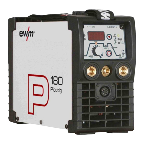
Machine description PICOTIG 180 Machine description PICOTIG 180 4.1.1 Front view Figure 4-1 Item Symbol Description Carrying strap Machine control See Machine control – operating elements chapter Connection socket, "+" welding current • TIG: Connection for workpiece lead • MMA: Electrode holder or workpiece lead connection... -
Page 16: Rear View
Machine description PICOTIG 180 4.1.2 Rear view NOTE The maximum possible machine configuration is given in the text description. If necessary, the optional connection may need to be retrofitted (see "Accessories" chapter). Figure 4-2 Item Symbol Description Main switch, machine on/off... -
Page 17: Picotig 180 Mv
Machine description PICOTIG 180 MV PICOTIG 180 MV 4.2.1 Front view Figure 4-3 Item Symbol Description Carrying strap Machine control See Machine control – operating elements chapter Connection socket, "+" welding current • TIG: Connection for workpiece lead • MMA: Electrode holder or workpiece lead connection... -
Page 18: Rear View
Machine description PICOTIG 180 MV 4.2.2 Rear view NOTE The maximum possible machine configuration is given in the text description. If necessary, the optional connection may need to be retrofitted (see "Accessories" chapter). Figure 4-4 Item Symbol Description Main switch, machine on/off... -
Page 19: Machine Control - Operating Elements
Machine description Machine control – Operating elements Machine control – Operating elements T 1.80 AMP% Figure 4-5 Item Symbol Description Three-figure LED display Welding parameter display (see also chap. “Welding data display”). "Select welding process" button MMA welding TIG welding (non-latched operating mode) TIG welding (latched operating mode) Green signal light: HF ignition (contact) switched on (factory setting) -
Page 20: Welding Data Display
Machine description Machine control – Operating elements 4.3.1 Welding data display The relevant value will be displayed on the welding data display depending on the parameters selected (currents or times). The display switches back to the setpoint value for the welding current after approx. 5 seconds. -
Page 21: Functional Characteristics
Functional characteristics TIG welding Functional characteristics TIG welding 5.1.1 Selection and adjustment Operating Action Result element Select welding process MMA welding TIG welding (non-latched operating mode) TIG welding (latched operating mode) Green signal light: HF ignition (non-contact) switched on Red signal light: Liftarc ignition (contact ignition) switched on Set welding current Select secondary current AMP%... -
Page 22: Arc Ignition
Functional characteristics TIG welding 5.1.3 Arc ignition NOTE The HF igntion type is factory set to active. The ignition types are switched over on the machine control, see also the "Advanced settings" chapter (TIG welding). 5.1.3.1 HF ignition Figure 5-1 The arc is started without contact from high-voltage ignition pulses. -
Page 23: Function Sequences/Operating Modes
Functional characteristics TIG welding 5.1.4 Function sequences/operating modes The parameters for the function sequence are set using the “Select welding parameters” button and the “Welding parameter setting” rotary dial. Pos. Description “Select welding parameters” button “Welding parameter setting” rotary dial Figure 5-3 Pressing the “Select welding parameters”... -
Page 24: Tig Non-Latched Operation
Functional characteristics TIG welding 5.1.4.2 TIG non-latched operation NOTE When the foot-operated remote control RTF is connected, the machine switches automatically to non-latched operation. The up- and down-slopes are switched off. Figure 5-4 1st cycle: • Press and hold torch trigger 1. •... -
Page 25: Tig Latched Operation
Functional characteristics TIG welding 5.1.4.3 TIG latched operation NOTE When the foot-operated remote control RTF is connected, the machine switches automatically to non-latched operation. The up- and down-slopes are switched off. Figure 5-5 1st cycle • Press torch trigger 1, the gas pre-flow time elapses. •... -
Page 26: Welding Torch (Operating Variants)
Functional characteristics TIG welding 5.1.5 Welding torch (operating variants) There is the option of connecting various operating and display elements to the welding torch. The functions of the torch triggers (TT) and the operating elements can be adjusted individually using different modes (see chapter “Setting the torch mode and up/down speed”). -
Page 27: Torch Mode And Up/Down Speed Setting
Functional characteristics TIG welding 5.1.6 Torch mode and up/down speed setting The user has the modes 1 to 3 and modes 11 to 13 available. Modes 11 to 13 include the same function options as 1 to 3, but without tapping function for the secondary current. The function options in the individual modes can be found in the tables for the corresponding torch types. -
Page 28: Standard Tig Torch (5-Pole)
Functional characteristics TIG welding 5.1.6.1 Standard TIG torch (5-pole) Standard torch with one torch trigger: Diagram Operating Explanation of symbols elements BRT1 = Torch trigger 1 (welding current on/off; secondary current via tapping function) Functions mode Operating elements BRT 1 Welding current On/Off (factory-set) BRT 1... - Page 29 Functional characteristics TIG welding Standard torch with one rocker (MG rocker, two torch triggers) Diagram Operating Explanation of symbols elements BRT 1 = torch trigger 1 BRT 2 = torch trigger 2 Functions mode Operating elements BRT 1 Welding current On/Off Secondary current BRT 2 (factory-set)
-
Page 30: Advanced Settings
Functional characteristics TIG welding 5.1.7 Advanced settings NOTE To change the advanced setting parameters, hold down the "Welding parameters" button for 2 seconds after selecting the welding process. The following diagram shows the setting options. Figure 5-7 Display Setting/selection Switch ignition mode on = HF ignition/off = Liftarc Switch on Switching on machine function... -
Page 31: Mma Welding
Functional characteristics MMA welding MMA welding 5.2.1 Selection and adjustment Operating Action Result element Select welding process MMA welding Set welding current NOTE This completes the basic settings and the welding work can now start. The hotstart current, hotstart time and arcforcing are factory-set to the optimum preset values for common applications. -
Page 32: Antistick
Functional characteristics MMA welding 5.2.4 Antistick Anti-stick prevents the electrode from annealing. If the electrode sticks in spite of the Arcforce device, the machine automatically switches over to the minimum current within about 1 second to prevent the electrode from overheating. Check the welding current setting and correct according to the welding task! 5.2.5 Advanced settings... -
Page 33: Remote Control
Functional characteristics Remote control Remote control NOTE These accessory components can be retrofitted as an option, see Accessories chapter. The remote control is operated on the 19-pole remote control connection socket. • If required, extension cables are available in different lengths (see chapter Accessories). •... -
Page 34: Commissioning
Commissioning General Commissioning General DANGER Risk of injury from electric shock! Contact with live parts, e.g. welding current sockets, is potentially fatal! • Follow safety instructions on the opening pages of the operating instructions. • Commissioning may only be carried out by persons who have the relevant expertise of working with arc welding machines! •... - Page 35 Commissioning Area of application – proper usage • MMA arc welding Item No.: 099-002046-EWM01...
-
Page 36: Installation
Commissioning Installation Installation CAUTION Installation site! The machine must not be operated in the open air and must only be set up and operated on a suitable, stable and level base! • The operator must ensure that the ground is non-slip and level, and provide sufficient lighting for the place of work. -
Page 37: Tig Welding
Connecting the welding torch and workpiece lead NOTE Prepare welding torch according to the welding task in hand (see operating instructions for the torch). 6.7.1.1 PICOTIG 180 Figure 6-1 Item Symbol Description Connection socket, "-" welding current Welding current lead connection for TIG welding torch G¼"... -
Page 38: Picotig 180 Mv
Commissioning TIG welding 6.7.1.2 PICOTIG 180 MV Figure 6-2 Item Symbol Description Connection socket, "-" welding current Welding current lead connection for TIG welding torch G¼" connecting nipple TIG welding torch shielding gas connection Connection socket, 5-pole Standard TIG torch control lead Connection socket for "+"... -
Page 39: Shielding Gas Supply (Shielding Gas Cylinder For Welding Machine)
Always re-fit the yellow protective cap when not using the shielding gas connection. • All shielding gas connections must be gas tight. 6.7.2.1 Connecting the shielding gas supply PICOTIG 180 PICOTIG 180 MV Figure 6-3 Item Symbol Description G¼” connecting nipple Shielding gas connection on the pressure reducer... -
Page 40: Setting The Shielding Gas Quantity
Commissioning TIG welding 6.7.2.2 Setting the shielding gas quantity CAUTION Electric shocks! When setting the shielding gas quantity, high voltage ignition pulses or open circuit voltage are applied at the welding torch; these can lead to electric shocks and burning on contact. -
Page 41: Mma Welding
Use insulated tongs to remove spent stick electrodes or to move welded workpieces and • Always put the electrode holder down on an insulated surface. 6.8.1 Connecting the electrode holder and workpiece lead 6.8.1.1 PICOTIG 180 Figure 6-4 Item Symbol Description Connection socket, “-” welding current Workpiece lead or electrode holder connection Connection socket for "+"... -
Page 42: Picotig 180 Mv
Commissioning MMA welding 6.8.1.2 PICOTIG 180 MV CAUTION Shielding gas connection! During MMA welding open circuit voltage is applied at the shielding gas connection (G¼" connecting nipple). • Place yellow insulating cap on the G¼" connection nipple (protects against electrical voltage and dirt). -
Page 43: Maintenance And Testing
– Inspection and testing during operation" in accordance with the German Ordinance of Operational Safety must be conducted correctly in order to qualify for claims under the EWM warranty. General When used in the specified environmental conditions and under normal operating conditions, this machine is largely maintenance-free and requires a minimum of care. -
Page 44: Test
DIN EN 61010-1 Appendix A – Measuring Circuit A1. You as the user are tasked with ensuring that your EWM machines conform to the standard IEC/DIN EN 60974-4 and are tested with the relevant test equipment and measuring devices given above. -
Page 45: Scope Of The Test
Maintenance and testing Test 7.3.2 Scope of the test a) Visual inspection b) Electrical test: measurement of • open circuit voltage • insulation resistance, or alternatively • leakage currents • protective conductor resistance c) Functional test d) Documentation 7.3.3 Visual inspection The key areas in the test are: 1. -
Page 46: Measuring The Leakage Current (Protective Conductor And Contact Current)
Note: Even if the leakage current measurement according to the standard is only an alternative to the insulation resistance measurement, EWM recommends always performing both measurements, especially following repair work. The leakage current is based for the greater part on a physical effect other than the insulation resistance. -
Page 47: Repair Work
Maintenance and testing Repair Work Repair Work Repair and maintenance work may only be performed by qualified authorised personnel; otherwise the right to claim under warranty is void. In all service matters, always consult the dealer who supplied the machine. Return deliveries of defective equipment subject to warranty may only be made through your dealer. -
Page 48: Disposing Of Equipment
Information about giving back used equipment or about collections can be obtained from the respective municipal administration office. • EWM participates in an approved waste disposal and recycling system and is registered in the Used Electrical Equipment Register (EAR) under number WEEE DE 57686922. •... -
Page 49: Warranty
• Wire feeds • Cooling units • Trolleys * If these are operated with genuine EWM accessories (such as intermediate tube package, remote control, remote control extension cable, coolant, etc.). 1-year warranty on: • Used EWM machines • Automation and mechanisation components •... -
Page 50: Warranty Declaration
This limitation does not apply to personal injuries or damage to property caused by negligent behaviour on the part of EWM. In no way will EWM be responsible for lost profits, indirect or subsequent damage. EWM is not liable for damages based on the claims of third parties. -
Page 51: Operating Problems, Causes And Remedies
Operating problems, causes and remedies Machine faults (error messages) Operating problems, causes and remedies All machines are subject to rigorous production checks and final checks. If despite this, anything fails to work at any time, please check the machine using the following chart. If none of the fault rectification procedures described leads to the correct functioning of the machine, please inform your authorised dealer. -
Page 52: Resetting Welding Parameters To The Factory Settings
Operating problems, causes and remedies Resetting welding parameters to the factory settings Resetting welding parameters to the factory settings NOTE All customised welding parameters that are stored will be replaced by the factory settings. Figure 9-1 Display Setting/selection Calibration The machine will be calibrated for approx 2 seconds each time it is switched on. Initialising All customised welding parameters that are stored will be replaced by the factory settings. -
Page 53: Display Machine Control Software Version
Operating problems, causes and remedies Display machine control software version Display machine control software version Figure 9-2 Display Setting/selection Calibration The machine will be calibrated for approx 2 seconds each time it is switched on. Exit the menu Exit Software version of the machine control Version display (example 2.4 = version 2.4) Item No.: 099-002046-EWM01... -
Page 54: Accessories, Options
ON ASM FR TIG Retrofit option to connect remote control 092-002111-00000 10.5.1 PICOTIG 180 Type Designation Item no. ON FILTER PICOTIG 180 Retrofit option, dirt filter for air inlet 092-002546-00000 10.5.2 PICOTIG 180 MV Type Designation Item no. ON FILTER MV/TETRIX 180... -
Page 55: Circuit Diagrams
Circuit diagrams PICOTIG 180 Circuit diagrams NOTE Original format circuit diagrams are located inside the machine. 11.1 PICOTIG 180 Figure 11-1 Item No.: 099-002046-EWM01... -
Page 56: Picotig 180 Mv
Circuit diagrams PICOTIG 180 MV 11.2 PICOTIG 180 MV Figure 11-2 Item No.: 099-002046-EWM01... -
Page 57: Declaration Of Conformity
Umbauten, die nicht ausdrücklich von authorised by EWM. bées n’ayant pas été autorisés expressé- EWM autorisiert sind, verliert diese ment par EWM, cette déclaration devient Erklärung ihre Gültigkeit. caduque. Gerätebezeichnung: Description of the machine: Déscription de la machine: Gerätetyp:...
Need help?
Do you have a question about the PICOTIG 180 and is the answer not in the manual?
Questions and answers