
Related Manuals for EWM Picotig 180


Summary of Contents for EWM Picotig 180
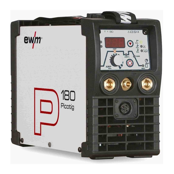
- Page 1 Operating instructions Welding machine Picotig 180 Picotig 180 MV 099-002046-EW501 16.11.2011...
-
Page 2: General Instructions
© EWM HIGHTEC WELDING GmbH · Dr. Günter-Henle-Str. 8 · D-56271 Mündersbach, Germany The copyright to this document remains the property of the manufacturer. -
Page 3: Table Of Contents
3.3.3 Welding in environments with increased electrical hazards......... 15 3.3.4 Service documents (spare parts and circuit diagrams) ..........15 4 Machine description – quick overview ....................16 Picotig 180 ........................... 16 4.1.1 Front view ........................16 4.1.2 Rear view........................17 Picotig 180 MV.......................... - Page 4 Standard TIG torch (5-pole) ................36 5.6.10 Advanced settings ......................38 MMA welding..........................39 5.7.1 Connecting the electrode holder and workpiece lead ..........39 5.7.1.1 Picotig 180.....................39 5.7.1.2 Picotig 180 MV ....................40 5.7.2 Selection and adjustment .....................41 5.7.3 Hotstart .........................41 5.7.4 Arcforce.........................41 5.7.5 Antistick.........................42 5.7.6...
- Page 5 Contents Notes on the use of these operating instructions 099-002046-EW501 16.11.2011...
-
Page 6: Safety Instructions
Safety instructions Notes on the use of these operating instructions Safety instructions Notes on the use of these operating instructions DANGER Working or operating procedures which must be closely observed to prevent imminent serious and even fatal injuries. • Safety notes include the "DANGER" keyword in the heading with a general warning symbol. •... -
Page 7: Explanation Of Icons
Safety instructions Explanation of icons Explanation of icons Symbol Description Press Do not press Turn Switch Switch off machine Switch on machine ENTER (enter the menu) NAVIGATION (Navigating in the menu) EXIT (Exit the menu) Time display (example: wait 4s/press) Interruption in the menu display (other setting options possible) Tool not required/do not use Tool required/use... -
Page 8: General
Safety instructions General General DANGER Electromagnetic fields! The power source may cause electrical or electromagnetic fields to be produced which could affect the correct functioning of electronic equipment such as IT or CNC devices, telecommunication lines, power cables, signal lines and pacemakers. •... - Page 9 Safety instructions General WARNING Smoke and gases! Smoke and gases can lead to breathing difficulties and poisoning. In addition, solvent vapour (chlorinated hydrocarbon) may be converted into poisonous phosgene due to the ultraviolet radiation of the arc! • Ensure that there is sufficient fresh air! •...
- Page 10 Safety instructions General CAUTION Damage due to the use of non-genuine parts! The manufacturer's warranty becomes void if non-genuine parts are used! • Only use system components and options (power sources, welding torches, electrode holders, remote controls, spare parts and replacement parts, etc.) from our range of products! •...
- Page 11 Safety instructions General CAUTION EMC Machine Classification In accordance with IEC 60974-10, welding machines are grouped in two electromagnetic compatibility classes (see technical data): Class A machines are not intended for use in residential areas where the power supply comes from the low-voltage public mains network.
-
Page 12: Transport And Installation
Safety instructions Transport and installation Transport and installation WARNING Incorrect handling of shielding gas cylinders! Incorrect handling of shielding gas cylinders can result in serious and even fatal injury. • Observe the instructions from the gas manufacturer and in any relevant regulations concerning the use of compressed air! •... -
Page 13: Ambient Conditions
Safety instructions Ambient conditions Ambient conditions CAUTION Installation site! The machine must not be operated in the open air and must only be set up and operated on a suitable, stable and level base! • The operator must ensure that the ground is non-slip and level, and provide sufficient lighting for the place of work. -
Page 14: Intended Use
Intended use Applications Intended use This machine has been manufactured according to the latest developments in technology and current regulations and standards. It must only be operated in line with the instructions on correct usage. WARNING Hazards due to improper usage! Hazards may arise for persons, animals and material objects if the equipment is not used correctly. -
Page 15: Documents Which Also Apply
Intended use Documents which also apply Documents which also apply 3.3.1 Warranty NOTE For further information, please see the accompanying supplementary sheets "Machine and Company Data, Maintenance and Testing, Warranty"! 3.3.2 Declaration of Conformity The designated machine conforms to EC Directives and standards in terms of its design and construction: •... -
Page 16: Machine Description - Quick Overview
Machine description – quick overview Picotig 180 Machine description – quick overview Picotig 180 4.1.1 Front view Figure 4-1 Item Symbol Description Carrying strap Machine control See Machine control – operating elements chapter Connection socket, "+" welding current • TIG: Connection for workpiece lead •... -
Page 17: Rear View
Machine description – quick overview Picotig 180 4.1.2 Rear view Figure 4-2 Item Symbol Description Main switch, machine on/off Connection socket, 19-pole Remote control connection G¼” connecting nipple Shielding gas connection on the pressure regulator. Mains connection cable Cooling air inlet 099-002046-EW501 16.11.2011... -
Page 18: Picotig 180 Mv
Machine description – quick overview Picotig 180 MV Picotig 180 MV 4.2.1 Front view Figure 4-3 Item Symbol Description Carrying strap Machine control See Machine control – operating elements chapter Connection socket, "+" welding current • TIG: Connection for workpiece lead •... -
Page 19: Rear View
Machine description – quick overview Picotig 180 MV 4.2.2 Rear view Figure 4-4 Item Symbol Description Main switch, machine on/off Connection socket, 19-pole Remote control connection G¼” connecting nipple Shielding gas connection on the pressure regulator. Mains connection cable Cooling air inlet 099-002046-EW501 16.11.2011... -
Page 20: Machine Control - Operating Elements
Machine description – quick overview Machine control – Operating elements Machine control – Operating elements Figure 4-5 Item Symbol Description Three-figure LED display Welding parameter display (see also chap. “Welding data display”). "Select welding process" button MMA welding TIG welding (non-latched operating mode) TIG welding (latched operating mode) Green signal light: HF ignition (contact) switched on (factory setting) -
Page 21: Welding Data Display
Machine description – quick overview Machine control – Operating elements 4.3.1 Welding data display The machine will be calibrated for approx. 2 seconds each time it is switched on. This will be indicated by on the display. Subsequently, the value set for the dynamic power adjustment will be displayed for approx. -
Page 22: Design And Function
Design and function General Design and function General WARNING Risk of injury from electric shock! Contact with live parts, e.g. welding current sockets, is potentially fatal! • Follow safety instructions on the opening pages of the operating instructions. • Commissioning may only be carried out by persons who have the relevant expertise of working with arc welding machines! •... -
Page 23: Transport And Installation
Design and function Transport and installation Transport and installation WARNING Risk of accident due to improper transport of machines that may not be lifted! Do not lift or suspend the machine! The machine can fall down and cause injuries! The handles and brackets are suitable for transport by hand only! •... -
Page 24: Mains Connection
Design and function Mains connection Mains connection DANGER Hazard caused by improper mains connection! An improper mains connection can cause injuries or damage property! • Only use machine with a plug socket that has a correctly fitted protective conductor. • If a mains plug must be fitted, this may only be carried out by an electrician in accordance with the relevant national provisions or regulations (any phase sequence for three-phase machines)! -
Page 25: Tig Welding
5.6.1 Welding torch and workpiece line connection NOTE Prepare welding torch according to the welding task in hand (see operating instructions for the torch). 5.6.1.1 Picotig 180 Figure 5-3 Item Symbol Description Welding torch Welding torch hose package Connection socket, "-" welding current Welding current lead connection for TIG welding torch G¼"... -
Page 26: Picotig 180 Mv
Design and function TIG welding 5.6.1.2 Picotig 180 MV Figure 5-4 Item Symbol Description Welding torch Welding torch hose package Connection socket, "-" welding current Welding current lead connection for TIG welding torch G¼" connecting nipple TIG welding torch shielding gas connection... -
Page 27: Shielding Gas Supply (Shielding Gas Cylinder For Welding Machine)
Design and function TIG welding 5.6.3 Shielding gas supply (shielding gas cylinder for welding machine) WARNING Incorrect handling of shielding gas cylinders! Incorrect handling of shielding gas cylinders can result in serious and even fatal injury. • Observe the instructions from the gas manufacturer and in any relevant regulations concerning the use of compressed air! •... -
Page 28: Setting The Shielding Gas Quantity
Design and function TIG welding Figure 5-6 Item Symbol Description G¼” connecting nipple Shielding gas connection on the pressure regulator. • Screw the gas hose connection nipple onto the G¼" connection nipple. 5.6.3.2 Setting the shielding gas quantity CAUTION Electric shocks! When setting the shielding gas quantity, high voltage ignition pulses or open circuit voltage are applied at the welding torch;... -
Page 29: Selection And Adjustment
Design and function TIG welding 5.6.4 Selection and adjustment Operating Action Result element Select welding process MMA welding TIG welding (non-latched operating mode) TIG welding (latched operating mode) Green signal light: HF ignition (non-contact) switched on Red signal light: Liftarc ignition (contact ignition) switched on Set welding current Select secondary current AMP% Set secondary current... -
Page 30: Arc Ignition
Design and function TIG welding 5.6.6 Arc ignition NOTE The HF igntion type is factory set to active. The ignition types are switched over on the machine control, see also the "Advanced settings" chapter (TIG welding). 5.6.6.1 HF ignition Figure 5-7 The arc is started without contact from high-voltage ignition pulses. -
Page 31: Function Sequences/Operating Modes
Design and function TIG welding 5.6.7 Function sequences/operating modes The parameters for the function sequence are set using the “Select welding parameters” button and the “Welding parameter setting” rotary dial. Figure 5-9 Item Symbol Description Select welding parameters button This button is used to select the welding parameters depending on the welding process and operating mode used. -
Page 32: Tig Non-Latched Operation
Design and function TIG welding 5.6.7.2 TIG non-latched operation NOTE When the foot-operated remote control RTF is connected, the machine switches automatically to non-latched operation. The up- and down-slopes are switched off. Figure 5-10 1st cycle: • Press and hold torch trigger 1. •... -
Page 33: Tig Latched Operation
Design and function TIG welding 5.6.7.3 TIG latched operation AMP% start Down Figure 5-11 Step 1 • Press torch trigger 1, the gas pre-flow time elapses. • HF ignition pulses jump from the electrode to the workpiece, the arc ignites. •... -
Page 34: Welding Torch (Operating Variants)
Design and function TIG welding 5.6.8 Welding torch (operating variants) There is the option of connecting various operating and display elements to the welding torch. The functions of the torch triggers (TT) and the operating elements can be adjusted individually using different modes (see chapter “Setting the torch mode and up/down speed”). -
Page 35: Torch Mode And Up/Down Speed Setting
Design and function TIG welding 5.6.9 Torch mode and up/down speed setting The user has the modes 1 to 3 and modes 11 to 13 available. Modes 11 to 13 include the same function options as 1 to 3, but without tapping function for the secondary current. The function options in the individual modes can be found in the tables for the corresponding torch types. -
Page 36: Standard Tig Torch (5-Pole)
Design and function TIG welding 5.6.9.1 Standard TIG torch (5-pole) Standard torch with one torch trigger: Diagram Operating Explanation of symbols elements BRT1 = Torch trigger 1 (welding current on/off; secondary current via tapping function) Functions mode Operating elements BRT 1 Welding current On/Off (factory-set) BRT 1... - Page 37 Design and function TIG welding Standard torch with one rocker (MG rocker, two torch triggers) Diagram Operating Explanation of symbols elements BRT 1 = torch trigger 1 BRT 2 = torch trigger 2 Functions mode Operating elements BRT 1 Welding current On/Off Secondary current BRT 2 (factory-set)
-
Page 38: 5.6.10 Advanced Settings
Design and function TIG welding 5.6.10 Advanced settings NOTE To change the advanced setting parameters, hold down the "Welding parameters" button for 2 seconds after selecting the welding process. The following diagram shows the setting options. Figure 5-13 Display Setting/selection Switch ignition mode on = HF ignition/off = Liftarc Switch on... -
Page 39: Mma Welding
Use insulated tongs to remove spent stick electrodes or to move welded workpieces and • Always put the electrode holder down on an insulated surface. 5.7.1 Connecting the electrode holder and workpiece lead 5.7.1.1 Picotig 180 Figure 5-14 Item Symbol Description Electrode holder Connection socket, “-” welding current... -
Page 40: Picotig 180 Mv
Design and function MMA welding 5.7.1.2 Picotig 180 MV CAUTION Shielding gas connection! During MMA welding open circuit voltage is applied at the shielding gas connection (G¼" connecting nipple). • Place yellow insulating cap on the G¼" connection nipple (protects against electrical voltage and dirt). -
Page 41: Selection And Adjustment
Design and function MMA welding 5.7.2 Selection and adjustment Operating Action Result element Select welding process MMA welding Set welding current NOTE This completes the basic settings and the welding work can now start. The hotstart current, hotstart time and arcforcing are factory-set to the optimum preset values for common applications. -
Page 42: Antistick
Design and function MMA welding 5.7.5 Antistick Anti-stick prevents the electrode from annealing. If the electrode sticks in spite of the Arcforce device, the machine automatically switches over to the minimum current within about 1 second to prevent the electrode from overheating. -
Page 43: Remote Control
Design and function Remote control Remote control NOTE The remote control is operated on the 19-pole remote control connection socket. 5.8.1 Foot-operated remote control RTF 1 Functions • Infinitely adjustable welding current (0% to 100%) depending on the preselected main current on the welding machine. •... -
Page 44: Maintenance, Care And Disposal
Maintenance, care and disposal General Maintenance, care and disposal DANGER Risk of injury from electric shock! Cleaning machines that are not disconnected from the mains can lead to serious injuries! • Disconnect the machine completely from the mains. • Remove the mains plug! •... -
Page 45: Maintenance Work
Information about giving back used equipment or about collections can be obtained from the respective municipal administration office. • EWM participates in an approved waste disposal and recycling system and is registered in the Used Electrical Equipment Register (EAR) under number WEEE DE 57686922. •... -
Page 46: Rectifying Faults
Rectifying faults Machine faults (error messages) Rectifying faults All products are subject to rigorous production checks and final checks. If, despite this, something fails to work at any time, please check the product using the following flowchart. If none of the fault rectification procedures described leads to the correct functioning of the product, please inform your authorised dealer. -
Page 47: Resetting Welding Parameters To The Factory Settings
Rectifying faults Resetting welding parameters to the factory settings Resetting welding parameters to the factory settings NOTE All customised welding parameters that are stored will be replaced by the factory settings. Figure 7-1 Display Setting/selection Calibration The machine will be calibrated for approx 2 seconds each time it is switched on. Initialising All customised welding parameters that are stored will be replaced by the factory settings. -
Page 48: Display Machine Control Software Version
Rectifying faults Display machine control software version Display machine control software version NOTE The query of the software versions only serves to inform the authorised service staff! Figure 7-2 Display Setting/selection Calibration The machine will be calibrated for approx 2 seconds each time it is switched on. Exit the menu Exit Service menu... -
Page 49: Dynamic Power Adjustment
Rectifying faults Dynamic power adjustment Dynamic power adjustment NOTE A correctly designed mains fuse is a prerequisite. • Observe the details about the mains fuse in the "Technical Data" chapter! The dynamic power adjustment automatically adjusts the welding performance to an uncritical level for the fuse. -
Page 50: Technical Data
Technical data Picotig 180 Technical data NOTE Performance specifications and guarantee only in connection with original spare and replacement parts! Picotig 180 Welding current setting range 5 A-180 A 5 A-150 A Welding voltage setting range 10.2 V-17.2 V 20.2 V-26.0 V Duty cycle (DC) at 25 °C... -
Page 51: Picotig 180
Technical data Picotig 180 MV Picotig 180 MV with connection voltage 230 V 115 V Setting ranges Welding current 5 A-180 A 5 A-300 A 5 A-150 A 5 A-110 A Welding voltage 10.2 V-17.2 V 20.2 V-26 V 10.2 V-16.0 V 20.2 V-24.4 V... -
Page 52: Accessories
Trolly 35-1 Transport vehicle 090-008629-00000 Options 9.2.1 Picotig 180 Type Designation Item no. ON Filter Pico/Picotig 180 Retrofit option, dirt filter for air inlet 092-002546-00000 9.2.2 Picotig 180 MV Type Designation Item no. ON Filter MV/Tetrix 180 Dirt filter for air inlet... -
Page 53: Machine Configuration Menu
Appendix A Machine configuration menu Appendix A 10.1 Machine configuration menu NOTE ENTER (enter the menu) • Switch off machine at the main switch • Press and hold the "welding parameters" button and switch the machine on again at the same time. -
Page 54: Overview Of Ewm Branches
Appendix B Overview of EWM branches Appendix B 11.1 Overview of EWM branches 099-002046-EW501 16.11.2011...
Need help?
Do you have a question about the Picotig 180 and is the answer not in the manual?
Questions and answers