
Related Manuals for EWM Picomig 185 puls TKG


Summary of Contents for EWM Picomig 185 puls TKG
- Page 1 Operating instructions Welding machine Picomig 185 puls TKG 099-005547-EW501 Observe additional system documents! 15.11.2022...
- Page 2 +49 2680 181-0. A list of authorised sales partners can be found at www.ewm-group.com/en/specialist-dealers. Liability relating to the operation of this equipment is restricted solely to the function of the equipment. No other form of liability, regardless of type, shall be accepted.
-
Page 3: Table Of Contents
Contents Notes on using these operating instructions Contents 1 Contents ............................3 2 For your safety ..........................5 Notes on using these operating instructions ................5 Explanation of icons ....................... 6 Safety instructions ........................7 Transport and installation ....................10 3 Intended use .......................... - Page 4 Contents Notes on using these operating instructions 5.3.3 Arcforce......................... 43 5.3.4 Hotstart ......................... 43 5.3.4.1 Hotstart settings ..................44 5.3.5 Antistick......................... 44 TIG welding .......................... 45 5.4.1 Preparing the TIG welding torch ................45 5.4.2 Welding torch and workpiece line connection ............45 5.4.3 Welding task selection ..................
-
Page 5: For Your Safety
For your safety Notes on using these operating instructions For your safety Notes on using these operating instructions DANGER Working or operating procedures which must be closely observed to prevent imminent serious and even fatal injuries. • Safety notes include the "DANGER" keyword in the heading with a general warning symbol. •... -
Page 6: Explanation Of Icons
For your safety Explanation of icons Explanation of icons Symbol Description Symbol Description Indicates technical aspects which the Activate and release / Tap / Tip user must observe. Switch off machine Release Switch on machine Press and hold Incorrect / Invalid Switch Correct / Valid Turn... -
Page 7: Safety Instructions
For your safety Safety instructions Safety instructions WARNING Risk of accidents due to non-compliance with the safety instructions! Non-compliance with the safety instructions can be fatal! • Carefully read the safety instructions in this manual! • Observe the accident prevention regulations and any regional regulations! •... - Page 8 For your safety Safety instructions WARNING Risk of injury due to improper clothing! During arc welding, radiation, heat and voltage are sources of risk that cannot be avoided. The user has to be equipped with the complete personal protective equipment at all times.
- Page 9 For your safety Safety instructions CAUTION Smoke and gases! Smoke and gases can lead to breathing difficulties and poisoning. In addition, solvent vapour (chlorinated hydrocarbon) may be converted into poisonous phosgene due to the ultraviolet radiation of the arc! • Ensure that there is sufficient fresh air! •...
-
Page 10: Transport And Installation
For your safety Transport and installation CAUTION Obligations of the operator! The respective national directives and laws must be complied with when operating the machine! • Implementation of national legislation relating to framework directive 89/391/EEC on the int- roduction of measures to encourage improvements in the safety and health of workers at work and associated individual guidelines. - Page 11 For your safety Transport and installation CAUTION Risk of accidents due to supply lines! During transport, attached supply lines (mains leads, control cables, etc.) can cause risks, e.g. by causing connected machines to tip over and injure persons! • Disconnect all supply lines before transport! Risk of tipping! There is a risk of the machine tipping over and injuring persons or being damaged itself during movement and set up.
-
Page 12: Intended Use
3.3.1 Warranty For more information refer to the "Warranty registration" brochure supplied and our information regarding warranty, maintenance and testing at www.ewm-group.com! 3.3.2 Declaration of Conformity This product corresponds in its design and construction to the EU directives listed in the decla- ration. -
Page 13: Part Of The Complete Documentation
Intended use Documents which also apply 3.3.6 Part of the complete documentation This document is part of the complete documentation and valid only in combination with all other parts of these instructions! Read and observe the operating instructions for all system components, especially the safety instructions! The illustration shows a general example of a welding system. -
Page 14: Machine Description - Quick Overview
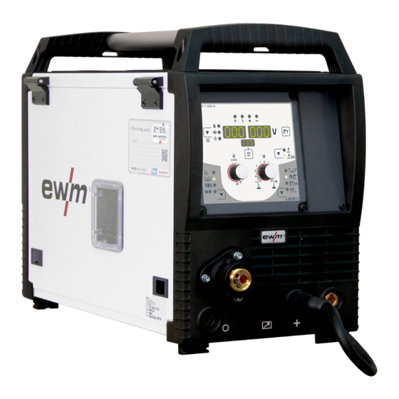
Machine description – quick overview Front view / rear view Machine description – quick overview Front view / rear view Figure 4-1 099-005547-EW501 15.11.2022... - Page 15 Machine description – quick overview Front view / rear view Item Symbol Description Carrying handle Machine control > see 4.3 chapter Welding torch connection (Euro torch connector) Welding current, shielding gas and torch trigger integrated Park socket, polarity selection plug Retainer for the polarity selection plug in MMA mode or for transport.
-
Page 16: Inside View
Machine description – quick overview Inside view Inside view Figure 4-2 Item Symbol Description Protective cap Cover for the wire feed mechanism and other operating elements. Depending on the machine series, additional stickers with information on the replace- ment parts and JOB lists will be located on the inside. Slide latch, lock for the protective cap Wire spool inspection window Check wire supply... -
Page 17: Machine Control - Operating Elements
Machine description – quick overview Machine control – Operating elements Machine control – Operating elements Figure 4-3 Item Symbol Description “Collective interference” signal light “Excess temperature” signal light Welding data display (3-digit) Displays the welding parameters and the corresponding values > see 4.3.1 chapter Welding parameter display mode/power-saving mode push-button ---------- Welding current ---------- Material thickness... - Page 18 Machine description – quick overview Machine control – Operating elements Item Symbol Description Operating mode button --------- Non-latched ------- Latched ----- Spots ----- Interval Runtime parameters button For selecting the parameters to be set. Also for entering and exiting the menus for ad- vanced settings.
-
Page 19: Welding Data Display
Machine description – quick overview Machine control – Operating elements 4.3.1 Welding data display Figure 4-4 The push-button for the welding parameter display mode is next to the display. Each time the push-button is pressed the display changes to the next parameter. After the last parameter is reached the display continues with the first parameter. -
Page 20: Design And Function
Design and function Transport and installation Design and function WARNING Risk of injury from electrical voltage! Contact with live parts, e.g. power connections, can be fatal! • Observe the safety information on the first pages of the operating instructions! • Commissioning must be carried out by persons who are specifically trained in handling power sources! •... -
Page 21: Machine Cooling
Design and function Transport and installation 5.1.2 Machine cooling Insufficient ventilation results in a reduction in performance and equipment damage. • Observe the ambient conditions! • Keep the cooling air inlet and outlet clear! • Observe the minimum distance of 0.5 m from obstacles! 5.1.3 Workpiece lead, general CAUTION... - Page 22 Design and function Transport and installation • Use an individual welding lead to the workpiece for each welding machine! Figure 5-2 • Fully unroll welding current leads, torch hose packages and intermediate hose packages. Avoid loops! • Always keep leads as short as possible! Lay any excess cable lengths in meanders.
-
Page 23: Stray Welding Currents
Design and function Transport and installation 5.1.5 Stray welding currents WARNING Risk of injury due to stray welding currents! Stray welding currents can destroy protective earth conductors, damage machines and electronic devices and cause overheating of components, leading to fire. •... -
Page 24: Welding Torch Holder
Design and function Transport and installation 5.1.6 Welding torch holder The item described in the following is part of the machine´s scope of delivery. Figure 5-5 Item Symbol Description Crossmember of the transport handle Torch holder Fixing screws (x 4) Fan-type lock washers •... -
Page 25: Mains Connection
Design and function Transport and installation 5.1.7 Mains connection DANGER Hazards caused by improper mains connection! An improper mains connection can cause injuries or damage property! • The connection (mains plug or cable), the repair or voltage adjustment of the device must be carried out by a qualified electrician in accordance with the respective local laws or nati- onal regulations! •... -
Page 26: Shielding Gas Supply (Shielding Gas Cylinder For Welding Machine)
Design and function Transport and installation 5.1.8 Shielding gas supply (shielding gas cylinder for welding machine) WARNING Risk of injury due to improper handling of shielding gas cylinders! Improper handling and insufficient securing of shielding gas cylinders can cause serious injuries! •... -
Page 27: Shielding Gas Hose Connection
Design and function Transport and installation 5.1.8.2 Shielding gas hose connection Figure 5-8 Item Symbol Description Connection thread - G¼" Shielding gas connection (inlet) • Screw the gas hose connection to the shielding gas connection (inlet) on the machine gas-tight. 5.1.8.3 Gas test –... -
Page 28: Mig/Mag Welding
Design and function MIG/MAG welding MIG/MAG welding 5.2.1 Welding torch and workpiece line connection On delivery, the Euro torch connector is fitted with a capillary tube for welding torches with a steel liner. Conversion is necessary if a welding torch with a liner is used! •... -
Page 29: Wire Feed
Design and function MIG/MAG welding • Insert the central plug for the welding torch into the central connector and screw together with crown nut. • Insert the plug of the workpiece lead in the respective welding current connection socket and lock in place by turning to the right. -
Page 30: Changing The Wire Feed Rollers
Design and function MIG/MAG welding • Unlock and open protective flap. • Loosen knurled nut from spool holder. • Fix welding wire reel onto the spool holder so that the carrier pin locks into the spool bore. • Fasten wire spool using knurled nut. Figure 5-11 Observe the unwinding direction of the wire spool. - Page 31 Design and function MIG/MAG welding Item Symbol Description Clamping unit Wire feed roller see the Wire feed roller overview table • Rotate the tommy by 90° clockwise or anti-clockwise (tommy locks into place). • Fold the closure brackets outwards by 90°. •...
- Page 32 Design and function MIG/MAG welding Unsatisfactory welding results due to faulty wire feeding! The wire feed rolls must be suitable for the diameter of the wire and the material. The wire feed rolls are colour-coded to facilitate distinction (see the Wire feed roll overview table). When working with a wire diameter of >...
-
Page 33: Inching The Wire Electrode
Design and function MIG/MAG welding 5.2.2.3 Inching the wire electrode CAUTION Risk of injury due to welding wire escaping from the welding torch! The welding wire can escape from the welding torch at high speed and cause bodily in- jury including injuries to the face and eyes! •... -
Page 34: Spool Brake Setting
Design and function MIG/MAG welding • The contact pressure has to be adjusted separately for each side (wire inlet/outlet) at the feed roll ten- sioner setting nuts depending on the welding consumable used. A table with the setting values can be found on a sticker near the wire drive. -
Page 35: Welding Task Selection
Design and function MIG/MAG welding 5.2.4 Welding task selection The settings for the respective welding parameters are defined by the different JOBs. The right JOB can be determined quickly with the JOB list > see 11.1 chapter. Figure 5-16 The settings for spot time, pause time and wire feed speed apply to all JOBs. All other parameter values are stored separately in each JOB. -
Page 36: Arc Length
Design and function MIG/MAG welding 5.2.5.3 Arc length If required, the arc length (welding voltage) can be corrected from -5 V to +5 V for the individual welding task. Figure 5-19 The basic settings are now completed. Other welding parameters have already been set optimally in the factory;... -
Page 37: Operating Modes (Functional Sequences)
Design and function MIG/MAG welding 5.2.7 Operating modes (functional sequences) 5.2.7.1 Explanation of signs and functions Symbol Meaning Press torch trigger Release torch trigger Shielding gas flowing Welding output Wire electrode is being conveyed Wire creep Wire burn-back Gas pre-flows Gas post-flows Non-latched Latched... - Page 38 Design and function MIG/MAG welding Non-latched mode Figure 5-21 Step 1 • Press and hold torch trigger. • Shielding gas is expelled (gas pre-flows). • Wire feed motor runs at “creep speed”. • Arc ignites after the wire electrode makes contact with the workpiece; welding current flows. •...
- Page 39 Design and function MIG/MAG welding Latched mode Figure 5-22 1. cycle • Press and hold torch trigger • Shielding gas is expelled (gas pre-flows) • Wire feed motor runs at “creep speed” • Arc ignites when the wire electrode makes contact with the workpiece Welding current flows •...
- Page 40 Design and function MIG/MAG welding Spot welding Figure 5-23 Start • Press and hold torch trigger. • Shielding gas is expelled (gas pre-flows). • Arc ignites after the wire electrode makes contact with the workpiece at creep speed. • Welding current flows. •...
-
Page 41: Conventional Mig/Mag Welding (Gmaw Non Synergic)
Design and function MIG/MAG welding Interval Figure 5-24 Start • Press and hold torch trigger. • Shielding gas is expelled (gas pre-flows). Sequence • Arc ignites after the wire electrode makes contact with the workpiece at creep speed. • Welding current flows. •... -
Page 42: Mma Welding
Design and function MMA welding MMA welding 5.3.1 Connecting the electrode holder and workpiece lead CAUTION Risk of crushing and burns! When changing stick electrodes there is a risk of crushing and burns! • Wear appropriate and dry protective gloves. •... -
Page 43: Arcforce
Design and function MMA welding 5.3.3 Arcforce During the welding process, arcforce prevents the electrode sticking in the weld pool with increases in current. This makes it easier to weld large-drop melting electrode types at low current strengths with a short arc in particular. -
Page 44: Hotstart Settings
Design and function MMA welding 5.3.4.1 Hotstart settings The setting ranges for the parameter values are summarised in the Parameter overview sec- tion > see 11.2 chapter. • Select MMA JOB 128 > see 5.3.2 chapter. Figure 5-30 Display Setting/selection Hotstart current Hotstart time 5.3.5... -
Page 45: Tig Welding
Design and function TIG welding TIG welding 5.4.1 Preparing the TIG welding torch The TIG welding torch is to be equipped to suit the relevant welding task! • Fit suitable tungsten electrodes and • an appropriate shielding gas nozzle. • Observe the operating instructions for the TIG welding torch! 5.4.2 Welding torch and workpiece line connection... -
Page 46: Welding Task Selection
Design and function TIG welding 5.4.3 Welding task selection • Select TIG JOB 127. You can only change the JOB number when no welding current is flowing. Figure 5-33 5.4.4 Adjusting the gas post-flow time • Preselection: Select TIG JOB 127 > see 5.4.3 chapter. Figure 5-34 Display Setting/selection... -
Page 47: Further Welding Parameters
Design and function TIG welding 5.4.5 Further welding parameters The setting ranges for the parameter values are summarised in the Parameter overview sec- tion > see 11.2 chapter. • Preselection: Select TIG JOB 127 > see 5.4.3 chapter. Figure 5-35 Display Setting/selection Gas pre-flow time... -
Page 48: Arc Ignition
Design and function TIG welding 5.4.6 Arc ignition 5.4.6.1 Liftarc Figure 5-36 The arc ignites through contact with the workpiece: a) Carefully place the torch gas nozzle and tungsten electrode tip against the workpiece (lift arc current flows independent of the set main current) b) Angle the torch above the torch gas nozzle until the distance between electrode tip and workpiece is approx. - Page 49 Design and function TIG welding Non-latched mode Figure 5-37 1st cycle • Press and hold torch trigger. • Shielding gas is expelled (gas pre-flows). The arc is ignited using liftarc. • The welding current flows with the value set for the starting current I start •...
- Page 50 Design and function TIG welding Latched mode Figure 5-38 1st cycle • Press and hold torch trigger. • Shielding gas is expelled (gas pre-flows). The arc is ignited using liftarc. • The welding current flows with the value set for the starting current I start 2nd cycle •...
-
Page 51: Machine Configuration Menu
Design and function Machine configuration menu Machine configuration menu 5.5.1 Selecting, changing and saving parameters Figure 5-39 Display Setting/selection Calibration The machine will be calibrated for approx 2 seconds each time it is switched on. Exit the menu Exit Machine configuration Settings for machine functions and parameter display Dynamic power adjustment >... -
Page 52: Power-Saving Mode (Standby)
Design and function Power-saving mode (Standby) Power-saving mode (Standby) You can activate the power-saving mode by either pressing the push-button > see 4.3 chapter for a pro- longed time or by setting a parameter in the machine configuration menu (time-controlled power-saving mode ) >... -
Page 53: Maintenance, Care And Disposal
Maintenance, care and disposal General Maintenance, care and disposal General DANGER Risk of injury due to electrical voltage after switching off! Working on an open machine can lead to fatal injuries! Capacitors are loaded with electrical voltage during operation. Voltage remains present for up to four minutes after the mains plug is removed. -
Page 54: Explanation Of Icons
Maintenance, care and disposal Explanation of icons Explanation of icons Personnel Welder / operator Qualified person (authorised service personnel) Tests Visual inspection Functional test Period, interval One-shift operation Multi-shift operation Every 8 hours Daily Weekly Monthly Every 6 months Annually Maintenance schedule Maintenance step Only personnel designated as inspectors or repairers due to their trai-... - Page 55 Maintenance, care and disposal Maintenance schedule Maintenance step Only personnel designated as inspectors or repairers due to their trai- ning are allowed to carry out the relevant work step! Non-applicable in- spection points are omitted. • Transport elements (strap, lifting eyes, handle, wheels, parking brake) corresponding safety elements (if necessary fuse caps) are present and flawless? •...
-
Page 56: Disposing Of Equipment
Information on returning used equipment or collections can be obtained from the respective municipal administration office. Devices can also be returned to EWM sales partners across Europe. Further information on the topic of the disposal of electrical and electronic equipment can be found on our website at: https://www.ewm-group.com/de/nachhaltigkeit.html. -
Page 57: Rectifying Faults
Rectifying faults Software version of the machine control Rectifying faults All products are subject to rigorous production checks and final checks. If, despite this, something fails to work at any time, please check the product using the following flowchart. If none of the fault rectification procedures described leads to the correct functioning of the product, please inform your authorised dea- ler. -
Page 58: Checklist For Rectifying Faults
Rectifying faults Checklist for rectifying faults Error message Possible cause Remedy Electronics error Switch the machine off and on again. If the error persists, notify service department Temperature error Allow the machine to cool down Motor fault Check wire feed mechanism, switch the machine off and on again, inform the service department if the fault persists. -
Page 59: Dynamic Power Adjustment
Rectifying faults Dynamic power adjustment Functional errors Mains fuse triggers - unsuitable mains fuse Set up recommended mains fuse > see 8 chapter. Machine does not start up after switching on (device fan and possibly coolant pump have no function). Connect the control cable of the wire feeder. -
Page 60: Resetting Welding Parameters To The Factory Settings
Rectifying faults Resetting welding parameters to the factory settings Resetting welding parameters to the factory settings All customised welding parameters that are stored will be replaced by the factory settings. RESET Figure 7-1 Display Setting/selection Calibration The machine will be calibrated for approx 2 seconds each time it is switched on. Initialising Keep the push-button pressed until is shown on the display. -
Page 61: Technical Data
Technical data Picomig 185 TKG Technical data Performance specifications and guarantee only in connection with original spare and replacement parts! Picomig 185 TKG MIG/MAG Welding current (I 5 A to 180 A 5 A to 150 A 5 A to 180 A Welding voltage according to stan- 14,3 V to 23,0 V 20,2 V to 26,0 V... -
Page 62: Accessories
Cross arm and holder for wire feeder 092-002700-00000 Options Type Designation Item no. ON XNET PICOMIG 3XX Retrofit option for connection to EWM Xnet over 092-004004-00000 Xnet LAN/Wi-Fi gateway ON D Barrel TG.0003 Wire guide Rolliner for drum feed 092-007929-00000 ON Case... -
Page 63: Replaceable Parts
Replaceable parts Wire feed rollers Replaceable parts Performance specifications and guarantee only in connection with original spare and replacement parts! 10.1 Wire feed rollers 10.1.1 Wire feed rollers for steel wire Type Designation Item no. FE 4R 0.6 MM/0.023 INCH Drive roll set, 37 mm, 4 rolls, V-groove for steel, 092-002770-00006 LIGHT PINK... -
Page 64: 10.1.3 Wire Feed Rollers For Cored Wire
Replaceable parts Wire feed rollers 10.1.3 Wire feed rollers for cored wire Type Designation Item no. FUEL 4R 0.8 MM/0.03 INCH Drive roll set, 37 mm, 4 rolls, V-groove/knurled for 092-002848-00008 WHITE/ORANGE flux cored wire 092-002848-00010 FUEL 4R 1.0 MM/0.04 INCH Drive roll set, 37 mm, 4 rolls, V-groove/knurled for BLUE/ORANGE flux cored wire... -
Page 65: Appendix
Appendix JOB-List Appendix 11.1 JOB-List We recommend using the characteristics for 1.0-mm solid wire electrodes also for the 0.9-mm solid wire electrodes. Figure 11-1 MIG/MAG pulse arc welding can be selected with JOBs 6, 34, 42, 74, 75, 76, 82, 83, 84, 90, 91, 110, 111, 114 and 115. - Page 66 Appendix Parameter overview – setting ranges MIG/MAG Gas pre-flow time 20,0 Dynamic correction Gas post-flow time 20,0 Spot time 20,0 Pause time (interval) 20,0 Wire burn-back Gas pre-flow time Start current Up-slope time 20,0 Down-slope time 20,0 End current Gas post-flow time 20,0 Arcforce correction Hot start current...
-
Page 67: Searching For A Dealer
Appendix Searching for a dealer 11.3 Searching for a dealer Sales & service partners www.ewm-group.com/en/specialist-dealers "More than 400 EWM sales partners worldwide" 099-005547-EW501 15.11.2022...
Need help?
Do you have a question about the Picomig 185 puls TKG and is the answer not in the manual?
Questions and answers