
Related Manuals for EWM Tetrix 152 RC Plasma CW GR


Summary of Contents for EWM Tetrix 152 RC Plasma CW GR
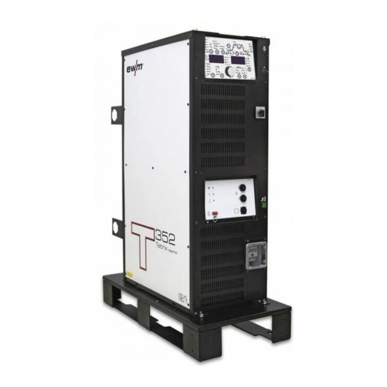
- Page 1 Operating instructions Power sources for automated applications Tetrix 152 RC Plasma CW GR Tetrix 352 RC Plasma CW GR Tetrix 552 RC Plasma CW GR 099-008724-EW501 Observe additional system documents! 08.01.2012...
- Page 2 © EWM HIGHTEC WELDING GmbH · Dr. Günter-Henle-Str. 8 · D-56271 Mündersbach, Germany The copyright to this document remains the property of the manufacturer.
-
Page 3: Table Of Contents
Contents Notes on the use of these operating instructions Contents 1 Contents..............................3 2 Safety instructions..........................5 Notes on the use of these operating instructions ................5 Explanation of icons........................6 General ............................7 Transport and installation ......................11 Ambient conditions........................12 2.5.1 In operation........................ - Page 4 Computer communication ......................59 Interfaces .............................60 Connection and extension cables ....................60 Connection cables........................60 10 Circuit diagrams ...........................61 10.1 Tetrix 152, 352, 552 RC Plasma CW GR ..................61 11 Appendix A............................66 11.1 JOB-List............................66 12 Appendix B............................70 12.1 Overview of EWM branches......................70 099-008724-EW501 08.01.2012...
-
Page 5: Safety Instructions
Safety instructions Notes on the use of these operating instructions Safety instructions Notes on the use of these operating instructions DANGER Working or operating procedures which must be closely observed to prevent imminent serious and even fatal injuries. • Safety notes include the "DANGER" keyword in the heading with a general warning symbol. •... -
Page 6: Explanation Of Icons
Safety instructions Explanation of icons Explanation of icons Symbol Description Press Do not press Turn Switch Switch off machine Switch on machine ENTER (enter the menu) NAVIGATION (Navigating in the menu) EXIT (Exit the menu) Time display (example: wait 4s/press) Interruption in the menu display (other setting options possible) Tool not required/do not use Tool required/use... -
Page 7: General
Safety instructions General General DANGER Electromagnetic fields! The power source may cause electrical or electromagnetic fields to be produced which could affect the correct functioning of electronic equipment such as IT or CNC devices, telecommunication lines, power cables, signal lines and pacemakers. •... - Page 8 Safety instructions General WARNING Smoke and gases! Smoke and gases can lead to breathing difficulties and poisoning. In addition, solvent vapour (chlorinated hydrocarbon) may be converted into poisonous phosgene due to the ultraviolet radiation of the arc! • Ensure that there is sufficient fresh air! •...
- Page 9 Safety instructions General CAUTION Damage due to the use of non-genuine parts! The manufacturer's warranty becomes void if non-genuine parts are used! • Only use system components and options (power sources, welding torches, electrode holders, remote controls, spare parts and replacement parts, etc.) from our range of products! •...
- Page 10 Safety instructions General CAUTION EMC Machine Classification In accordance with IEC 60974-10, welding machines are grouped in two electromagnetic compatibility classes (see technical data): Class A machines are not intended for use in residential areas where the power supply comes from the low-voltage public mains network.
-
Page 11: Transport And Installation
Safety instructions Transport and installation Transport and installation WARNING Incorrect handling of shielding gas cylinders! Incorrect handling of shielding gas cylinders can result in serious and even fatal injury. • Observe the instructions from the gas manufacturer and in any relevant regulations concerning the use of compressed air! •... -
Page 12: Ambient Conditions
Safety instructions Ambient conditions Ambient conditions CAUTION Installation site! The machine must not be operated in the open air and must only be set up and operated on a suitable, stable and level base! • The operator must ensure that the ground is non-slip and level, and provide sufficient lighting for the place of work. -
Page 13: Intended Use
3.1.4 TIG activArc welding The EWM activArc process, thanks to the highly dynamic controller system, ensures that the power supplied is kept virtually constant in the event of changes in the distance between the welding torch and the weld pool, e.g. during manual welding. Voltage losses as a result of a shortening of the distance between the torch and molten pool are compensated by a current rise (ampere per volt - A/V), and vice versa. -
Page 14: Use And Operation Solely With The Following Machines
Intended use Use and operation solely with the following machines Use and operation solely with the following machines • BUSINT X11* • RINT X12 • T drive 4 Rob 2 • T drive 4 Rob 3 RE • T drive 4 Rob 3 LI •... -
Page 15: Machine Description - Quick Overview
Machine description – quick overview Tetrix 152, 352, 552 RC Plasma CW GR Machine description – quick overview Tetrix 152, 352, 552 RC Plasma CW GR NOTE The maximum possible machine configuration is given in the text description. If necessary, the optional connection may need to be retrofitted (see "Accessories" chapter). - Page 16 Machine description – quick overview Tetrix 152, 352, 552 RC Plasma CW GR Item Symbol Description Machine control See Machine control – operating elements chapter Cooling air inlet Main switch, machine on/off Automatic cutouts • Fuse protection for the pilot arc power source •...
-
Page 17: Rear View
Machine description – quick overview Tetrix 152, 352, 552 RC Plasma CW GR 4.1.2 Rear view Figure 4-2 099-008724-EW501 08.01.2012... - Page 18 Machine description – quick overview Tetrix 152, 352, 552 RC Plasma CW GR Item Symbol Description Interfaces connection socket (15-pole) digital Mains connection cable 19-pole mechanised welding interface (analogue) (See chapter entitled "Design and function > interfaces".) analog Key button, automatic cutout Wire feed motor supply voltage fuse press to reset a triggered fuse 7-pole connection socket (digital)
-
Page 19: Machine Control
Machine description – quick overview Machine control Machine control T 3.47 Puls Automatic AMP% AMP% AMP% > HOLD hotwire VOLT Synergic RC PROG wirefeeder hotwire Figure 4-3 Item Symbol Description Tungsten electrode diameter/ignition optimisation ∅ 1.0 mm, ∅ 1.6 mm, ∅ 2.0 mm, ∅ 2.4 mm, ∅ 3.2 mm, ∅ 4.0 mm or more Optimum ignition and stabilisation of the arc The selectable welding current is limited to the maximum welding current of the tungsten electrode. - Page 20 Machine description – quick overview Machine control Item Symbol Description Signal light for wire feeder Signal light for hot wire power source Operating mode spotArc (Setting range for spot time 0.01 s to 20.0 s) Non-latched Latched Display switching key button AMP hotwire not selectable VOLT...
-
Page 21: Function Sequence
Machine description – quick overview Machine control 4.2.1 Function sequence AMP% AMP% AMP% activArc Figure 4-4 Item Symbol Description Select welding parameters button This button is used to select the welding parameters depending on the welding process and operating mode used. Gas pre-flow time (TIG) absolute setting range 0.0 sec to 20.0 sec (0.1s increments). - Page 22 Machine description – quick overview Machine control Item Symbol Description AMP% End-crater current (TIG) Setting range 1 % to 200 % (1 % increments). Percentage of the main current. Gas post-flow time (TIG) Setting ranges: 0.00 sec to 40.0 sec (0.1 sec increments). Balance TIG DC pulses (15 kHz) Setting range: 1% to +99% (1% increments).
-
Page 23: Plasmadrive
Machine description – quick overview Plasmadrive Plasmadrive Figure 4-5 Item Symbol Description Welding torch head Wire delivery unit cover Plasmadrive Filler wire drive Sensor voltage connection for the filler wire fusing detection Contact pressure roller lock Contact pressure setting (hexagon socket) Drive rollers Anticollision device connection Reverse inching button... -
Page 24: Insufficient Wire" Sensor
Machine description – quick overview "Insufficient wire" sensor "Insufficient wire" sensor Figure 4-6 Item Symbol Description "Insufficient wire" sensor control lead plug Wire feed rapid-action closure Connection to wire source Wire exit rapid-action closure Connection to wire feed connection hose "Insufficient wire"... -
Page 25: Design And Function
Design and function General Design and function NOTE Observe documentation of other system components when connecting! General WARNING Risk of injury from electric shock! Contact with live parts, e.g. welding current sockets, is potentially fatal! • Follow safety instructions on the opening pages of the operating instructions. •... -
Page 26: Transport And Installation
Design and function Transport and installation CAUTION Damage due to incorrect connection! Accessory components and the power source itself can be damaged by incorrect connection! • Only insert and lock accessory components into the relevant connection socket when the machine is switched off. •... -
Page 27: Welding Torch Cooling System
Design and function Welding torch cooling system Welding torch cooling system 5.5.1 General CAUTION Coolant mixtures! Mixtures with other liquids or the use of unsuitable coolants result in material damage and renders the manufacturer's warranty void! • Only use the coolant described in this manual (overview of coolants). •... -
Page 28: Mains Connection
Design and function Mains connection Mains connection DANGER Hazard caused by improper mains connection! An improper mains connection can cause injuries or damage property! • Only use machine with a plug socket that has a correctly fitted protective conductor. • If a mains plug must be fitted, this may only be carried out by an electrician in accordance with the relevant national provisions or regulations (any phase sequence for three-phase machines)! -
Page 29: System Gas Connection
Design and function System gas connection System gas connection WARNING Incorrect handling of shielding gas cylinders! Incorrect handling of shielding gas cylinders can result in serious and even fatal injury. • Observe the instructions from the gas manufacturer and in any relevant regulations concerning the use of compressed air! •... - Page 30 Design and function System gas connection Figure 5-2 Item Symbol Description G1/4" connecting nipple, shielding gas connection Connection to the pressure reducer G1/4" connecting nipple, plasma gas connection Connection to the pressure reducer • Screw the connection coupling of the plasma gas line onto the G1/4" connecting nipple, plasma gas connection.
-
Page 31: Connecting The Shielding Gas Supply
Design and function System gas connection 5.7.1 Connecting the shielding gas supply Figure 5-3 Item Symbol Description Pressure regulator Shielding gas cylinder Output side of the pressure regulator Cylinder valve • Place the shielding gas cylinder into the relevant cylinder bracket. •... -
Page 32: Welding Torch Connection
Design and function Welding torch connection Welding torch connection CAUTION Use of unsuitable coolants results in damage to the welding torch! Unsuitable coolants can cause damage to the welding torch! • Use only DKF 23E coolants (observe temperature range of 0°C bis + 40°C). NOTE Please note the relevant documentation of the accessory components. - Page 33 Design and function Welding torch connection Item Symbol Description Plasma torch Welding torch hose package 23-pole connection socket (analogue) Mechanised welding torch connection Connection socket, welding current - Welding torch connection Pilot current connection socket Plasma welding torch nozzle potential G1/4"...
-
Page 34: Welding Torch Connection
Design and function Welding torch connection 5.8.1 Welding torch connection NOTE Before commissioning, the plasma welding torch must be equipped for the welding JOB and correspondingly set/adjusted! Figure 5-5 Item Symbol Description G1/4" shielding gas connecting nipple, welding machine output Connection to the welding torch or gas metering unit (GMU) Adapter (G1/4 >... -
Page 35: Connecting The Wire Feed Unit
Design and function Connecting the wire feed unit Connecting the wire feed unit Figure 5-6 Item Symbol Description Wire feed unit Control lead package 7-pole connection socket (digital) Wire feed unit connection 12-pole connection socket (analogue) Wire feed unit connection •... -
Page 36: Insufficient Wire" Sensor Connection
Design and function "Insufficient wire" sensor connection 5.10 "Insufficient wire" sensor connection Figure 5-7 Item Symbol Description "Insufficient wire" sensor A warning is issued as soon as the end of the wire (insufficient wire) is reached. The process will not be shut down. "Insufficient wire"... -
Page 37: Cooling Module Connection
Design and function Cooling module connection 5.11 Cooling module connection CAUTION Use of unsuitable coolants results in damage to the welding torch! Unsuitable coolants can cause damage to the welding torch! • Use only DKF 23E coolants (observe temperature range of 0°C bis + 40°C). NOTE Observe the fitting and connection instructions given in the relevant operating instructions for the cooling unit. - Page 38 Design and function Cooling module connection Item Symbol Description Cooling unit Cooling unit voltage supply Protective contact socket Quick connect coupling (red) Coolant return to cooling unit Rapid-action closure nipple Coolant return from welding torch Plasma torch Quick connect coupling, blue Coolant supply to the welding torch •...
-
Page 39: Connection For Workpiece Lead
Design and function Connection for workpiece lead 5.12 Connection for workpiece lead Figure 5-9 Item Symbol Description Workpiece Connection socket, “+” welding current Connection for workpiece lead • Insert the cable plug on the work piece lead into the "+" welding current connection socket and lock by turning to the right. -
Page 40: Arc Ignition
Design and function Arc ignition 5.13 Arc ignition The pilot arc is switched on and off using the pilot arc button „On/Off“. After switching on the pilot arc, the gas pre-flow time set starts running, the pilot arc current ignites without workpiece contact between the electrode and nozzle, and the control lamp in the pressure switch comes on. -
Page 41: Interfaces
Design and function Interfaces 5.15 Interfaces 5.15.1 Connecting the robot interface / industrial bus interface CAUTION Damage due to the use of non-genuine parts! The manufacturer's warranty becomes void if non-genuine parts are used! • Only use system components and options (power sources, welding torches, electrode holders, remote controls, spare parts and replacement parts, etc.) from our range of products! •... -
Page 42: Rint X11 Robot Interface
Design and function Interfaces Figure 5-10 Item Symbol Description 7-pole connection socket (digital) For connecting digital accessory components Switching cabinet Robot interface / Industrial bus interface Interface casing ATCASE Connection cable, 7-pole Connection between switching cabinet and power source Connection cables, 12-, 19- and 23-pole Connection between interface casing and switching cabinet 5.15.1.1 RINT X11 robot interface The standard digital interface for mechanised applications•... -
Page 43: Connecting The Pc 300.Net Welding Parameterisation Software
Design and function Interfaces 5.15.2 Connecting the PC 300.net welding parameterisation software Create all welding parameters quickly on the PC and easily transfer them to one or more welding machines (accessories, set consisting of software, interface, connection leads) Figure 5-11 Item Symbol Description PC interface, serial (D-Sub connection socket, 9-pole) -
Page 44: Connecting The Q-Doc 9000 V2.0 Welding Data Documentation Software
Design and function Interfaces 5.15.3 Connecting the Q-DOC 9000 V2.0 welding data documentation software (Accessories: Set consisting of software, interface, connection leads) The ideal tool for welding data documentation of, for example: welding voltage and current, wire speed and motor current. Figure 5-12 Item Symbol Description... -
Page 45: Connecting The Weldqas Welding Data Monitoring And Documentation System
Design and function Interfaces 5.15.4 Connecting the WELDQAS welding data monitoring and documentation system Network-compatible welding data monitoring and documentation system for digital power sources. Figure 5-13 Item Symbol Description 7-pole connection socket (digital) For connecting digital accessory components Windows PC WELDQAS welding data monitoring and documentation system Connection cable, 7-pole Connection between switching cabinet and power source... -
Page 46: Automation Interface
Design and function Interfaces 5.15.5 Automation interface WARNING No function of the external shut-down devices (emergency stop switch)! If the emergency stop circuit has been realised using an external shut-down device via the interface for mechanised welding, the device must be set for this setup. If this is not observed, the power source will ignore the external shut-down devices and will not shut down! •... - Page 47 Design and function Interfaces 19-pole pin assignment for interface for automated welding (X6): Signal form Signal name circuit Function diagram Output Connection for cable screen Input PULSING ON Thermal pulse mode up to max. 50 Hz, fixed balance of Output Sticking Analysis signal to detect sticking of the filler wire to the workpiece 24 V = sticking...
-
Page 48: Connection Socket Automation Torch
Design and function Interfaces 5.15.6 Connection socket automation torch X14- Brennerkoll. +24V Brenn. +24V Brenn. 0V Tacho Gastest Brenner Gastest Brenner Einfädeln Brenner Einfädeln Brenner Tacho 5V Tacho 5V Tacho Sig. Tacho Sig. Tacho 0V Tacho 0V Ausf. Br. Ausf. Br. Fühlerstrom Figure 5-15 Connection socket 23-pole Automation torch:... -
Page 49: Sensor Current
Design and function Interfaces 5.15.7 Sensor current The sensor current is transferred via the connection socket of the automated welding torch. At the torch, the signal has to be connected to the conducting part of the cold wire feeder. This means outside the welding process an electric potential is active which detects sticking when the feeder or wire has contact with the workpiece at the end of the process. -
Page 50: Maintenance, Care And Disposal
Maintenance, care and disposal General Maintenance, care and disposal DANGER Risk of injury from electric shock! Cleaning machines that are not disconnected from the mains can lead to serious injuries! • Disconnect the machine completely from the mains. • Remove the mains plug! •... -
Page 51: Annual Test (Inspection And Testing During Operation)
Maintenance, care and disposal Maintenance work 6.2.3 Annual test (inspection and testing during operation) NOTE The welding machine may only be tested by competent, capable personsl. A capable person is one who, because of his training, knowledge and experience, is able to recognise the dangers that can occur while testing welding power sources as well as possible subsequent damage and who is able to implement the required safety procedures. -
Page 52: Disposing Of Equipment
Information about giving back used equipment or about collections can be obtained from the respective municipal administration office. • EWM participates in an approved waste disposal and recycling system and is registered in the Used Electrical Equipment Register (EAR) under number WEEE DE 57686922. •... -
Page 53: Rectifying Faults
Rectifying faults Checklist for rectifying faults Rectifying faults All products are subject to rigorous production checks and final checks. If, despite this, something fails to work at any time, please check the product using the following flowchart. If none of the fault rectification procedures described leads to the correct functioning of the product, please inform your authorised dealer. - Page 54 Rectifying faults Checklist for rectifying faults Wire feed problems Unsuitable or worn welding torch equipment Adjust contact tip (cold wire/hot wire) to wire diameter, blow through and replace if necessary Adjust wire guide to material in use, blow through and replace if necessary Contact tip blocked Clean, spray with anti-spatter spray and replace if necessary Setting the spool brake (see "Setting the spool brake"...
-
Page 55: Machine Faults (Error Messages)
Rectifying faults Machine faults (error messages) Machine faults (error messages) NOTE A welding machine error is indicated by the collective fault signal lamp (A1) lighting up and an error code (see table) being displayed in the machine control display. In the event of a machine error, the power unit shuts down. -
Page 56: General Operating Problems
Rectifying faults General operating problems Error message Possible cause Remedy Err 20 Coolant Check coolant level and refill if necessary The flow quantity of the torch coolant • Check coolant level in the reverse cooler has fallen below the permissible •... -
Page 57: Vent Coolant Circuit
Rectifying faults Vent coolant circuit Vent coolant circuit NOTE Coolant tank and quick connect coupling of coolant supply and return are only fitted in machines with water cooling. To vent the cooling system always use the blue coolant connection, which is located as deep as possible inside the system (close to the coolant tank)! Figure 7-1 099-008724-EW501... -
Page 58: Technical Data
Technical data Tetrix 152, 352, 552 RC Plasma CW GR Technical data NOTE Performance specifications and guarantee only in connection with original spare and replacement parts! Tetrix 152, 352, 552 RC Plasma CW GR Welding current 5 A to 150 A 5 A to 350 5 A to 550 A Welding voltage... -
Page 59: Accessories
094-000207-00000 Computer communication Type Designation Item no. RC 300 EWM tablet PC incl. software, adapter and interface 090-008238-00002 PC300.Net PC300.Net welding parameter software set incl. 090-008265-00000 cable and SECINT X10 USB interface WELDQAS2 Station Stationary welding data monitoring and docu set for... -
Page 60: Interfaces
Accessories Interfaces Interfaces Type Designation Item no. Tetrix BUSINT X11 PLASMA RUGGED LINE industrial bus interface in casing 090-008623-00000 RUGGED LINE Tetrix BUSINT X11 PLASMA PROFIBUS industrial bus interface in casing 090-008624-00000 PROFIBUS ATCASE Tetrix BUSINT X11 PLASMA PROFINET LWL industrial bus interface in casing 090-008625-00000 PROFINET LWL ATCASE Tetrix BUSINT X11 PLASMA... -
Page 61: Circuit Diagrams
Circuit diagrams Tetrix 152, 352, 552 RC Plasma CW GR Circuit diagrams NOTE Original format circuit diagrams are located inside the machine. 10.1 Tetrix 152, 352, 552 RC Plasma CW GR Figure 10-1 099-008724-EW501 08.01.2012... - Page 62 Circuit diagrams Tetrix 152, 352, 552 RC Plasma CW GR X4/12 X4/11 X4/10 X4/9 X4/8 X4/7 X4/6 X4/5 X4/4 X4/3 X4/2 X4/1 Figure 10-2 099-008724-EW501 08.01.2012...
- Page 63 Circuit diagrams Tetrix 152, 352, 552 RC Plasma CW GR Figure 10-3 099-008724-EW501 08.01.2012...
- Page 64 Circuit diagrams Tetrix 152, 352, 552 RC Plasma CW GR D-Sub. 15polig Figure 10-4 099-008724-EW501 08.01.2012...
- Page 65 Circuit diagrams Tetrix 152, 352, 552 RC Plasma CW GR Figure 10-5 099-008724-EW501 08.01.2012...
-
Page 66: Job-List
Appendix A JOB-List Appendix A 11.1 JOB-List Process Material Wire Seam position ∅ Reserved CrNi CrNi CrNi CrNi CrNi CrNi >3.2 CrNi CrNi CrNi CrNi CrNi CrNi >3.2 CrNi CrNi CrNi CrNi CrNi CrNi >3.2 CrNi CrNi CrNi CrNi CrNi CrNi >3.2 Fe/St... - Page 67 Appendix A JOB-List Process Material Wire Seam position ∅ Fe/St Fe/St >3.2 Fe/St Fe/St Fe/St Fe/St Fe/St Fe/St >3.2 Fe/St Fe/St Fe/St Fe/St Fe/St Fe/St >3.2 >3.2 >3.2 >3.2 >3.2 099-008724-EW501 08.01.2012...
- Page 68 Appendix A JOB-List Process Material Wire Seam position ∅ CuZn CuZn CuZn CuZn CuZn CuZn >3.2 CuZn CuZn CuZn CuZn CuZn CuZn >3.2 CuZn CuZn CuZn CuZn CuZn CuZn >3.2 CuZn CuZn CuZn CuZn CuZn CuZn >3.2 Special Special Special Special Special Special...
- Page 69 Appendix A JOB-List Process Material Wire Seam position ∅ Special Special Special Special >3.2 Special Special Special Special Special Special >3.2 TIG manual/TIG classic Classic electrode Reserved Reserved Reserved Electrode JOB Reserved 129-179 Free JOBs or SCO (e.g. plasma) CrNi CrNi CrNi >3.2...
-
Page 70: Overview Of Ewm Branches
Appendix B Overview of EWM branches Appendix B 12.1 Overview of EWM branches 099-008724-EW501 08.01.2012...
Need help?
Do you have a question about the Tetrix 152 RC Plasma CW GR and is the answer not in the manual?
Questions and answers