Table of Contents
Advertisement
Advertisement
Table of Contents

Related Manuals for Wellav UMH160R


Summary of Contents for Wellav UMH160R
- Page 1 Professional HD Integrated Receiver Decoder User Manual V1.02-N...
-
Page 2: About This Manual
Preface About This Manual This manual provides introductions to users about how to operate the device correctly. The content includes introduction to product installation, product characteristics and product settings, etc. It is highly suggested users to go through this document before actually operating the device. - Page 3 Tips that help you to solve problems or save your time. Remarks. Additional information to the text, in order to emphasize something. Revision History The revision history lists the modification history. The newest one contains all the modifications of the past revision. ...
-
Page 4: Table Of Contents
Contents About This Product ......................4 1.1 Introduction ........................ 4 1.2 Safety ........................4 1.3 Architecture ....................... 5 1.4 Methods of Operation ....................7 1.4.1 Operation through WEB UI ................7 1.4.2 Operation through Front Panel Operation ............7 1.5 Technical Specifications .................... 8 1.5.1 Physical Specifications ................... -
Page 5: About This Product
1 About This Product 1.1 Introduction This product is a new generation integrated receiver decoder to support the growing demands for multi-format, multi-standard video delivery and distribution. It can receive digital signals from several of inputs (DVB-S/S2, DVB-C (optional), DVB-T/ISDB-T (optional) and ASI), decrypt, and process/select programs to various outputs including CVBS, HDMI, SD/HD SDI and ASI. -
Page 6: Architecture
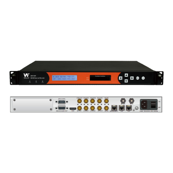
having special regards to EMC, and where technical personnel are present with experience of EMC technology.) 1.3 Architecture The equipment of this section is shown in schematic diagram. It is subject to change for improvement on the real product without advanced notice. Front Panel PIC-1.3-1 1. - Page 7 Rear Panel (UMH160R-Base) 17 3 5 7 9 12 13 1 17 2 4 6 8 10 PIC-1.3-2 HDMI Output L-Audio 1 R-Audio 1 L-Audio 2 R-Audio 2 CVBS AES/EBU ASI Out ASI IN MANAGEMENT RF IN Balanced L/R Analog Audio Out2...
-
Page 8: Methods Of Operation
1.4 Methods of Operation 1.4.1 Operation through WEB UI Operate the IRD remotely through WEB UI. The WEB UI operation supports: Functions Description Related Items WEB UI allows users to conduct operations of Signal receive setup Parameters parameters CI setup Setting configuration, Decoder setup... -
Page 9: Technical Specifications
Decoder Max. Resolution 1920 X 1080i CI Max. Output Bitrate 100Mbps 1.5.3 Interfaces and Protocols Physical Connector Interfaces IP input (UMH160R-AD ) ASI input Interface: 2 ASI inputs, 75Ω Interface: 1 x 1000 Mbps MPEG Format: 188/204 Bytes per IP Encapsulation: UDP/RTP... - Page 10 IP output (UMH160R-AD ) ASI output Interface: 2 ASI outputs, 75Ω Interface: RJ 45 MPEG Format: 188/204 Bytes per IP Encapsulation: UDP/RTP Outputs MPEG TS: MPTS and SPTS Max bit rate: 120 Mbps (per TS) Output processing: Up to 12 Sockets, max at 72 Mbps per socket.
-
Page 11: Installation
2 Installation 2.1 Installation Procedure Preparation before Installation Check Package and Accessories Setup Connection (signals, wiring) Parameters Configuration System Debug Finish 2.2 Preparation before Installation Before installation, the installation personnel should read through and confirm the followings: Go through this user manual. ... -
Page 12: Check Package And Accessories
2.3 Check Package and Accessories The IRD package includes the following accessories: Base Unit x1 Power cord x1 Earth cord x1 BNC cord x1 BNC-RCA cord x2 User Guide Disc x1 2.4 Equipment Wiring and Connection To avoid electric shock and damage to the equipment, before setting up the wiring connection, please power off the equipment and all other connected external devices. -
Page 13: Connection Setup For Rf Signal Input
Connection Diagram (For UMH 106R-AD) PIC-2.4-2 In actual application, not all connection interfaces need to be connected with signal/external devices. Please connect according to actual application purpose. To ensure a smooth communication between the management PC and the IRD, please try to connect the IRD management port to a switch without large data processing. -
Page 14: Connection Setup For Asi Signal Input
2.4.3 Connection Setup for ASI signal input (UMH160R-AD) Connect IP signal to IRD “TS/IP” port with a twisted cable. Connect the IRD “Management” port to a switch, set up a management network with the management PC. Connect the IRD with the monitor via HDMI, SDI or CVBS ports. -
Page 15: Operation Guide
Switch on the equipment through the rear power switch, and the unit is powered up and starts the initialization. The LCD screen is lighted up, and display information as following: UMH160R IRD Booting… The initialization takes about 20 seconds to complete, and then the IRD shows the IP... -
Page 16: Front Panel Menu Structure
Ok to configure the IRD parameters. The configuration and settings are displayed through front panel LCD. 3.3.1 Front Panel Menu Structure For UMH 160R-BASE: Layer Layer Layer Layer Default Settings Source Select Tuner 1 Tuner 2 LNB Frequency 5150MHz Satellite Frequency 3840MHz Symbol Rate 27500KBaud... - Page 17 Setup Video standard Auto Video Aspect Ratio Auto Video Format 1080i Audio Volume Audio Mixer Stereo Audio Audio1 Language Audio2 Language Subtitle Standard Subtitle Subtitle Language DHCP Enable Local IP Address 192.168.0.16 Local Network Mask 255.255.255.0 Local Setup Local Gateway 192.168.1.1 Trap IP Address 000.000.000.000...
- Page 18 RF Level TS Rate Tuner 1 Status FEC Rate Frequency Offset Tuner 2 Frequency Tune RF Level TS Rate Program No. program PCR PID Output information Audio PID Status program list Video PID PMT PID CI Slot1 EMPTY CI Status CI Slot2 EMPTY CIMultiDecryntMode...
-
Page 19: Front Panel Operation Guide
Ethernet Host IP Address 192.168.1.98 Host Subnet Mask 255.255.255.0 Host Gateway 192.168.1.1 Host MAC Address Trap IP Address1 000.000.000.000 Trap IP Address1 000.000.000.000 System Language English Factory Setting Power Alarm Clear Power Alarm Eth Control Reset Eth Version Software version Hardware version 3.3.2 Front Panel Operation Guide ... -
Page 20: Web Ui Operation (Recommended)
Press arrow UP button and arrow DOWN to input / select an appropriate setting, then press OK button to save. 3.4. WEB UI Operation (Recommended) Accessing the equipment via Web can be very convenient for remote configuration of the equipment. Relative to the front panel settings WEB operation can provide a more friendly man-machine interface, and with less limits in space. - Page 21 2. The IRD default IP address is 192.168.1.16. Please modify the management server’s IP address or IRD IP address to be in the same IP section. To ensure that the equipment is smoothly connected to the network. 3. Open any web browser (e.g. Mozilla, internet explorer, safari and etc.), input the equipment’s IP address in format: http://xxx.xxx.xxx.xxx (xxx.xxx.xxx.xxx refers to IRD’s IP address) and press ENTER button to confirm.
-
Page 22: Parameters Configuration
For UMH 160R-AD: To login, you need to enter the default username “admin” and password “admin”. Then click “Submit”. If the user name and password is entered correctly, you will be redirected directly to the main page. 3.4.2 Parameters Configuration 3.4.2.1 Main Page PIC-3.4-4... - Page 23 configure or monitor, then the detailed information will appear in the right area. Left menu section for UMH 160R-BASE/L/SDI: PIC-3.4-5 Left menu section for UMH 160R-AD: PIC-3.4-6 Right function section: This section is the main place for monitor and configuration of the machine, it can show you the detailed information, you can operate it as follows:...
- Page 24 3.4.2.2 Status Page ( For UMH160R-BASE/UMH 160R-L/ UMH 160R-SDI ) PIC-3.4-7 This page shows the current operation status of the equipment. Therefore, you can monitor and check the following: General Status: if the signal locked, it shows the signal status in green, otherwise, it shows in red.
- Page 25 3.4.2.3 Status Page (For UMH160R-AD) This page allows you to monitor the status of input and output signal, and check the information of CI cards. PIC-3.4-8 Input status (tuner/ ASI/ IP): It shows the main information of input streams, such as lock status, RF BER, RF Level, Total RF Rate , ASI total rate, ASI effective rate etc.
- Page 26 PIC-3.4-9 ① Input Program Configuration:The “Input Program Configuration” is on the left side of the window. It displays all the information input module and the received input streams ② Output Program Configuration:In the “Output Program Configuration” window, it shows the ports which can be set to transmit output stream. The programs set to be outputted are shown in the submenu of each port.
- Page 27 PIC-3.4-10 After completing the scan, all the input programs of that port will be scanned and displayed as follows: PIC-3.4-11 How to configure the output programs: Firstly, select the port which you want to transmit the output stream. Right click the TS in that port and a pop-up menu will appear.
- Page 28 button. Then input “Original Network ID” and “TS ID” will be assigned to the selected output TS (channel). PIC-3.4-13 Additionally, by clicking the editing icon, you are able to modify the TS name, network ID and TS ID. And you can delete the existing TS by click the cross icon as follows: PIC-3.4-14 Note: after completing the configuration, you should click “Apply”...
- Page 29 PIC-3.4-15 Source Select In this interface, you can select any of the two sources as input: PIC-3.4-16 1. TUNER: the IRD will search the signal from the tuner source (need to enter accurate parameters for the signal to lock). 2.
- Page 30 PIC-3.4-17 RF Auto-Switch: when one of the tuner input is interrupted, it will turn to the other tuner input automatically. And you can stop this function by set the value to disable. ASI Auto-Input: this is used to refresh the monitoring information automatically, when the input ASI rate changes.
- Page 31 to receive satellite signal with different polarization. Generally 18V is for Horizontal while 13V is for Vertical. LNB 22 KHz: Generally this is used to control 22KHz switch, typically used for LNB with double L.O. in Ku band. “ON” is for high L.O and “OFF” is for low L.O.
- Page 32 parameter from the satellite program provider. SYMBOL RATE (KBaud): every transponder has one symbol rate; you can get this parameter from the satellite program provider. LNB LO. Frequency: this is the LNB’s local oscillation (LO) frequency, every LNB have one or two oscillation frequencies which can be obtained from the LNB provider, or you can check on the LNB label.
- Page 33 This page shows the local IP setup and Input IP information. There are two channels available to receive IP streams. Before you can receive the IP streams, you should configure the following parameters: IPAddress: Local IP setting for connecting to the server. This IP and the management server’s IP should be in the same section.
- Page 34 PIC-3.4-21 The device decoding output is via its CVBS or HDMI output ports. For each time only one program can be set to decoding output. The parameters set in “Program Setup” interface work for all selected program. PROGRAM: This interface, all the programs received will be listed in “Source Select” region. By changing the program’s operation, you can determine whether to transmit the program or appoint a CI Slot to descramble the scrambled programs.
- Page 35 CAM: In this section, by changing the CAM operation, you can determine whether to descramble the program or not. Options for operation: PIC-3.4-23 o BYPASS: to transmit the program without any disposal. o CI SLOT 1 / CI SLOT 2: Common Interface slot. If the program is scrambled, you can appoint the CAM module with CAM Card to scramble it.
- Page 36 DVB SUBTITLE LANG: If there is multiple subtitle languages are supplied in the program signal, user can select which subtitle language to decode from the options. The first language is set to be the default value. EBU SUBTITLE LANG: If there is multiple subtitle languages are supplied in the program signal, user can select which subtitle language to decode from the options.
- Page 37 o Subtitle Language: Here you can set the language of subtitle from the existing selections. 3.4.2.8 Outputs ( For UMH 160R-AD) Decoder This page shows the video parameter and audio parameter: PIC-3.4-27 Video: Here, you can configure the video parameter, as follows: PIC-3.4-28 o VIDEO STANDARD: in this item, you can select video standard including Auto, SECAM, NTSC, PAL-N, PAL-M and PAL.
- Page 38 The decoder output video resolution should meet with the monitor resolution setting to avoid and display issue. Audio: In this section, you can configure the information of Audio, as follows: PIC-3.4-29 o AUDIO Volume: Set the output audio level from 0 to max. 49. o Mixer: Shows the format of audio, including Stereo, Left, Right, Mono and Dual.
- Page 39 PIC-3.4-31 Enable: Enable or disable corresponding output channel Dest IP Address: The IP address for the multicast/unicast. Dest Port: The port of the multicast/unicast, it must stay same with the value of the dest device. Protocol: You can choose UDP OR RTP for multicast/unicast. ...
- Page 40 o CI MULTIDECYPT MODE: CombinedPMT: convert the PMTs of all selected programs together to a CAPMT and then send this CAPMT to CAM for processing. This setting is in order to let the IRD work more compliantly with some special CAMs.
- Page 41 LocalSetup PIC-3.4-33 In this page, you are able to configure the following parameters: IP ADDRESS: Local IP setting for connecting to the server. This IP and the management server’s IP should be in the same section. Network MASK: Network Mask setting for connecting to the server. It should be the same as management server: 255.255.255.0 ...
- Page 42 Alarms setup PIC-3.4-35 In this section, you can set the alarm information to monitor the device and signal. After setting the “Alarm Mask” on, the “GPI” item will be optional. If you set the GPI on, when there are LNB Disconnect, Signal unlocked, CAM error, decoder failure, ASI output lost error, the alarm information will be sent out via GPI.
- Page 43 Here, you can change the existed username to a new one. Create a User: The device allows you to add up to 10 new users to operate the device. You can set the new username and password after select “Create a User” button. ...
- Page 44 avoid unexpected things. When you finish the configuration, you’d better save it as backup. And from the “override Exiting” selection you can review the existed backup. Rename Configuration: If there are many configuration backup, you can rename it with a new name to distinguish from others.
- Page 45 This interface will show a “FactorySetting” button. Once you clicked it, all the parameter will become default value. Log ( For UMH 160R-BASE/ UMH 160R-L/ UMH 160R-SDI) PIC-3.4-40 Here, you can get and import the log of the device for further analysis. And by clicking the ClearLog button, you are able to clear the redundancy log data.
-
Page 46: Operation Verification
PIC-3.4-42 This interface will show a “Reset” button, once you click a prompt message will appear asking for verification. Then the equipment will reboot automatically. Before you reset the device you’d better save the configuration of the equipment. 3.5. Operation Verification This section briefly describes some simple verification/debugging on the device after configuring the parameters of the device. -
Page 47: Descrambling Function Verification
Verification Result Once the signal source is properly connected and the parameters based on the input is accurately configured, front panel LOCK indicator will lights up in GREEN, indicating that the signal reception is normal. 3.5.2 Descrambling Function Verification Precondition: Scrambled satellite signal or test stream are available. -
Page 48: Preparation Before Officially Operation
module and authorized smart card. The descrambled picture can be seen via the monitor. The configuration of IRD: The items need to be checked are listed in the following table. Items Method Outputs->Program Setup menu (for scrambled program) (Select the program which needs to be descrambled from Program List. -
Page 49: Clear All Useless Data
3.6.1 Clear all useless data To do a factory default setting on the device in order to clean up all test data generated in the process of debugging and testing. 3.6.2 Configure the equipment with working data According to the formal system plan to configure the IRD from signal input, descramble and decoding output. -
Page 50: Faq
4 FAQ Problem Possible Reasons What to do Check whether the power The LCD display on the front No power. cord is plugged into the panel does not light up. power socket. Parameters are not Check the parameters properly configured. configuration Check the source and No signal... - Page 51 Problem Possible Reasons What to do Check the cable connections, LNB and No cable connection or the other equipment program does not exist in connected between the current satellite. LNB and the STB, and /or No or bad signal. adjust the dish. The satellite dish is not Align the dish.
-
Page 52: Terminology
Problem Possible Reasons What to do Make sure the cable is good one and connect well Network cable problem to the IRD management port. Haven’t selected decrypted Select decrypted programs programs or select to be correctly. incorrectly. CAM Modular Error. Change for another CAM. - Page 53 International Standard Organization International Telecommunications Union Low Noise Block MPEG Moving Pictures Experts Group PCMCIA Personal Computer Memory Card International Association Real-time Transport Protocol Standard Definition Serial Digital Interface Transport Stream User Datagram Protocol...
Need help?
Do you have a question about the UMH160R and is the answer not in the manual?
Questions and answers