Table of Contents
Advertisement
Quick Links
Advertisement
Table of Contents

Related Manuals for Silicon Graphics Rackable C2110G-RP5


Summary of Contents for Silicon Graphics Rackable C2110G-RP5
- Page 1 ® Rackable ™ C2110G-RP5 System User Guide 007-5841-001...
- Page 2 © 2012 SGI. All rights reserved; provided portions may be copyright in third parties, as indicated elsewhere herein. No permission is granted to copy, distribute, or create derivative works from the contents of this electronic documentation in any manner, in whole or in part, without the prior written permission of SGI.
-
Page 3: Record Of Revision
Record of Revision Version Description May, 2012 First release 007-5841-001... -
Page 5: About This Guide
Audience This guide is written for users of SGI Rackable C2110G-RP5 server systems. It is written with the assumption that the reader has a good working knowledge of computers and computer systems. This guide may be useful to installers and system administrators looking for overview information on the server. - Page 6 Provides best practice procedures to work with a node board in the C2110G-RP5 chassis, install memory DIMMs, PCIe expansion cards and hard disk drives. • Chapter 6, “Basic Troubleshooting and Chassis Service” Describes some basic steps required to troubleshoot your system. Additional sections in this chapter are intended to guide you through basic component remove and replace procedures.
-
Page 7: Related Publications
SGI InfiniteStorage series documentation • Man pages (online) You can obtain SGI documentation (as well as the pertinent LSI books), release notes, or man pages in the following ways: • Refer to the SGI Technical Publications Library at http://docs.sgi.com. Various formats are available. -
Page 8: Product Support
If you are in North America, contact the Technical Assistance Center at +1 800 800 4SGI or contact your authorized service provider. • If you are outside North America, contact the SGI subsidiary or authorized distributor in your country. viii... - Page 9 If you have comments about the technical accuracy, content, or organization of this document, contact SGI. Be sure to include the title and document number of the manual with your comments. (Online, the document number is located in the front matter of the manual. In printed manuals, the document number is located at the bottom of each page.)
-
Page 11: Table Of Contents
Contents Introduction Server Board Features . Processors . QPI Interconnect Memory . Serial ATA . PCI Express Expansion Slots . Onboard Controllers/Ports . Onboard Graphics Controller . IPMI Other Features . Server Chassis Features . System Power . Serial ATA Subsystems Front Control Panel . - Page 12 Contents Mechanical Loading . . 11 Circuit Overloading . . 12 Reliable Ground . . 12 Install the System into a Rack . 12 Separate the Sections of the Rack Rails . . 12 Attaching the Outer Rack Rails . .
- Page 13 Contents Serverboard Details . . 31 CPUs . . 32 Memory . 32 GPUs . . 32 PCIe Expansion Slots . . 32 System Health Monitoring . . 32 ACPI Features . . 33 Onboard I/O . 33 Serverboard Dimensions . .
- Page 14 Contents Removing the Power Supply . 48 Installing a New Power Supply. . 48 Accessing the Inside of the Chassis . . 50 System Fans . . 50 System Fan Failure . . 50 Replacing System Fans . . 50 Remove/Replace a Fan .
-
Page 15: Introduction
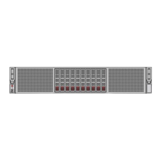
When required, SGI provides these drivers on an SGI Driver CD, which may ship with the system, or on the system disk (pre-installed in the factory). For more information on this topic check with your sales or service representative. - Page 16 1: Introduction Note: The Rackable C2110G-RP5 server does not use an internal CD/DVD drive. Check with your SGI sales or service representative for information on optional external CD/DVD drive units. Ten disk drive bays Main power System reset System IPMI...
-
Page 17: Server Board Features
Server Board Features Server Board Features At the heart of the system is a dual-processor serverboard based on the Intel C602 chipset and designed to provide maximum performance. The main features of the serverboard are described in the following subsections. Processors The serverboard supports two four, six or eight-core, Intel Xeon E5-2600 series processors. -
Page 18: Pci Express Expansion Slots
IPMI IPMI (Intelligent Platform Management Interface) is a hardware-level interface specification that provides remote access, monitoring and administration for your SGI Rackable C2110G-RP5 server platforms. IPMI allows server administrators to view a server’s hardware status remotely, receive an alarm automatically if a failure occurs, and power cycle a system that is non-responsive. -
Page 19: Server Chassis Features
Server Chassis Features Server Chassis Features The following subsections provide a general outline of the main features of the SGI Rackable C2110G-RP5 server chassis. System Power The Rackable C2110G-RP5 2U server chassis features a redundant power supply composed of two separate power modules. This power redundancy feature allows you to replace a failed power supply without shutting down the system. -
Page 20: Gpu Features
1: Introduction Important: Check with your SGI sales or service representative prior to using any GPU not sourced at the SGI factory. Any combination of these cards (up to a total of four) may have come bundled with the system. - Page 21 Server Chassis Features #1-4 #0-4 #0-3 #1-3 #1-2 #0-2 #1-1 #0-1 E5-2600 Series E5-2600 Series 8 SNB CORE 8 SNB CORE DDR-III DDR-III DMI2 DMI2 PCI-E X16 G3 PCI-E X16 G3 PCI-E X16 G3 PCI-E X16 G3 I350/X540 PCI-E X8 G3 DMI2 4GB/s SATA3...
-
Page 23: Server Installation
Chapter 2 Server Installation This chapter provides a quick setup checklist to get the SGI Rackable C2110G-RP5 operational. If your system came already mounted in a rack, you can skip the rack installation procedures. Unpack the System Inspect the shipping container that the C2110G-RP5 was shipped in and note if it was damaged in any way. -
Page 24: System Warnings And Precautions
System Warnings and Precautions Warning: The SGI Rackable C2110G-RP5 server weighs up to 57 lbs (25.9 kg). Always use proper lifting techniques when you move the server. Always get the assistance of another qualified person when you install the sever in a location above your shoulders. Failure to do so may result in serious personal injury or damage to the equipment. -
Page 25: Server Precautions
Rack Mounting Considerations Server Precautions • Review the electrical and general safety precautions. • Determine the placement of each component in the rack before you install the rails. • Install the heaviest server components in the bottom of the rack first, and then work up. •... -
Page 26: Circuit Overloading
Note that the inner rail may be pre-installed on the server by the SGI factory making separation steps unnecessary. To separate the inner and outer rails, perform the following steps:... - Page 27 Install the System into a Rack Figure 2-2 Separating the Rack Rails 007-5841-001...
-
Page 28: Attaching The Outer Rack Rails
2: Server Installation Attaching the Outer Rack Rails Outer rails attach to the rack and hold the chassis in place. They extend between 26.5 and 36.4 inches. Measure the depth of the rack (distance from the front rail to the rear rail) to ensure it complies with the limitations listed in the previous subsections. -
Page 29: The Inner Rail Extension
Install the System into a Rack Extending the Rails Quick- Release Tab Separating the Inner Rail Extension Figure 2-4 Outer Rack Rail Extension Example The Inner Rail Extension The chassis includes a set of factory-installed inner rails in two sections: inner rails and inner rail extensions. -
Page 30: Install The Server In A Rack
Install the Server in a Rack Warning: The SGI Rackable C2110G-RP5 server weighs up to 57 lbs (25.9 kg) Always use proper lifting techniques when your move the server. Always get the assistance of another qualified person when you install the sever in a location above your shoulders. - Page 31 Install the System into a Rack Figure 2-5 Installing the Server in the Rack 007-5841-001...
-
Page 32: Supply Power To The System
2: Server Installation Supply Power to the System Connect the power cords from the power supply modules into a power strip or power distribution unit (PDU) within the rack. An optionally available uninterruptible power supply (UPS) can ensure continued operation in case of a failure of the regular power source. After all power connections are verified, push the power-on button on the front of the server when you wish to power on the unit. -
Page 33: System Interface
Chapter 3 System Interface Overview There are several LEDs on the front control panel as well as others on the drive carriers and power supplies to keep you constantly informed of the overall status of the system. See Figure 3-1 for an example of the front control panel. -
Page 34: Control Panel Buttons
3: System Interface Control Panel Buttons In addition to monitoring the activity and health of specific components using LEDs, the system uses two buttons located on the front of the chassis: a reset button and a power on/off button. Use the reset button to reboot the system as shown in Figure 3-2. -
Page 35: Control Panel Leds
Control Panel LEDs Control Panel LEDs The control panel located on the front of the chassis has several LEDs. These LEDs provide you with critical information related to different parts of the system. This section explains what each LED indicates when illuminated or flashing and any corrective action you may need to take. Power Fail LED The power fail LED indicates a power supply module has failed as shown in Figure... -
Page 36: Nic1
3: System Interface NIC1 When flashing, the NIC1 LED indicates network activity on the LAN1 port (see Figure 3-6). Figure 3-6 LAN1 Network Activity NIC1 LED NIC2 When flashing, the NIC2 LED indicates network activity on the LAN2 port (see Figure 3-7). -
Page 37: Power
Drive Carrier LEDs Power The power LED indicates power is being supplied to the system's power supply unit(s). An example LED is shown in Figure 3-9. This LED should normally be illuminated when the system is operating. Figure 3-9 Power On LED Drive Carrier LEDs The system hard disk drives each have two LEDs, that function as listed in the following two paragraphs:... -
Page 39: System Safety
Electrical Safety Precautions Basic electrical safety precautions should be followed to protect yourself from harm and the Rackable C2110G-RP5 system from damage, as follows: • Be aware of the locations of the power on/off switch on the chassis as well as the room's emergency power-off switch, disconnection switch or electrical outlet. -
Page 40: Serverboard Battery
4: System Safety Serverboard Battery Caution: There is a danger of explosion if an onboard battery is installed upside down, which will reverse its polarities (see Figure 4-1). This battery must be replaced only with the same or an equivalent type recommended by the manufacturer. Check with your service representative if you have any questions. -
Page 41: Mainboard Replaceable Soldered-In Fuses
General Safety Precautions Follow these rules to ensure general safety: • Keep the area around the Rackable C2110G-RP5 system clean and free of clutter. • The Rackable C2110G-RP5 system weighs approximately 57 lbs (25.9 kg.) when fully loaded. When lifting the system, two people at either end should lift slowly with their feet spread out to distribute the weight. - Page 42 4: System Safety • Remove any jewelry or metal objects from your body, which are excellent metal conductors that can create short circuits and harm you if they come into contact with printed circuit boards or areas where power is present. •...
-
Page 43: System And Serverboard Information
Contact your local customer support office: http://www.sgi.com/support/supportcenters.html Caution: Install the chassis cover after you have completed accessing the components inside the server to maintain proper airflow and cooling for the system. -
Page 44: Esd Precautions
5: System and Serverboard Information ESD Precautions • Use a grounded wrist strap designed to prevent electrostatic discharge. • Touch a grounded metal object before removing any board from its antistatic bag. • Handle each printed circuit board (PCB) by the edges; do not touch the components, peripheral chips, memory modules, or gold contacts on the PCB. -
Page 45: System Rear I/O Ports
System Rear I/O Ports System Rear I/O Ports The rear external system I/O ports are color coded in conformance with the PC 99 specification. Figure 5-1 below for the colors and locations of the various I/O ports. Table 5-1 identifies the functions of each of the I/O ports on the backpanel. -
Page 46: Cpus
5: System and Serverboard Information CPUs • The C602 chipsets are used on the system serverboard Memory • Eight DIMM slots supporting 1600/1333/1066/800 MHz registered ECC SDRAM Note: Check with your authorized sales/service representative for installation of approved DIMM types. GPUs •... -
Page 47: Acpi Features
System Rear I/O Ports ACPI Features • Microsoft OnNow available • Slow blinking LED for suspend state indicator • BIOS support for USB keyboard • Wake-On-LAN (WOL) • Internal/external modem ring-on • Hardware BIOS Virus protection Onboard I/O • Ten 2.5-inch SATA drive bays supported by an on-chip SATA controller (RAID 0, 1 and 10 software RAID are supported using controllers on the system serverboard) Note: RAID 5 and RAID 6 functionality is supported with the use of optional hardware. - Page 48 5: System and Serverboard Information USB/0/1 S/IO JVGA1 JWD1 JPG1 IPMI LAN JLAN2 JLAN1 BMC CTRL LAN CTRL JI2C2 JI2C1 BIOS Battery JBT1 CLOSE 1st CPU1 OPEN 1st JPW1 X9DRG-HF Rev. 1.01 JPW4 CLOSE 1st CPU2 CPU2 JPW3 OPEN 1st Figure 5-2 Node Board Features 007-5841-001...
-
Page 49: Hard Disk Drives (C2110G-Rp5 Chassis)
Figure 5-3 C2110G-RP5 System Disk Drive Locations Drive Configurations The disk drive configurations supported in the Rackable C2110G-RP5 server are outlined in the paragraphs that follow. Note that some configurations are dependent on use of optional hardware to support RAID configurations. - Page 50 5: System and Serverboard Information • RAID 1 Disk “mirroring”, supports exactly two drives. The two drives represent one RAID 1 logical drive. The operating system will be installed on the drives located in Drive positions 0 and 1. Note that both drives 0 and 1 must be of the same type, speed and capacity. •...
-
Page 51: Pcie Expansion Cards
One PCI-E 2.0 x4 standard-depth card Note: Only specific GPU cards will fit and function in the internal PCIe GPU slots, contact your SGI sales or service representative for information on approved GPU cards. Power Supply Functional Rating The C2110G-RP5 server default configuration is two rear-installed 1800-watt power supplies. -
Page 53: Basic Troubleshooting And Chassis Service
Basic Troubleshooting Procedures Use the information in the following subsections to remedy basic problems you might encounter when working with the Rackable C2110G-RP5 server. If the System Does Not Power Up If the system will not power up when the front power button is pushed, use the following checklist to identify common sources for the problem: •... -
Page 54: System Powers Up But Will Not Boot
6: Basic Troubleshooting and Chassis Service System Powers Up But Will Not Boot If the system powers up but will not boot the Operating System, check the following: • Check the system order document(s) - the C2110G-RP5 server may have been ordered with no operating system. -
Page 55: Chassis Service Information
Chassis Service Information • You should be using registered ECC DDR3 memory. Also, it is recommended that you use the same memory type and speed for all DIMMs in the system. • Contact your administrator or support provider if the memory errors continue. Chassis Service Information The following sections cover the steps required to install components and perform maintenance on the C2110G-RP5 chassis. -
Page 56: Unpacking
6: Basic Troubleshooting and Chassis Service • For grounding purposes, make sure your computer chassis provides excellent conductivity between the power supply, the case, the mounting fasteners and the serverboard. Unpacking Replacement components are usually shipped in antistatic packaging to avoid static damage. When unpacking an upgrade or replacement component, make sure the person handling it is static protected. -
Page 57: Removing Hard Drives Or Carriers From The Chassis
Drive Bay Installation/Removal Removing Hard Drives or Carriers from the Chassis Press the release button on the drive carrier. This extends the drive carrier handle. 2. Use the handle to pull the drive carrier out of the chassis. Important: Empty carriers without drives must stay in the chassis during operation for proper airflow/cooling purposes except during remove/replace operations. -
Page 58: Hard Drive Carrier Assembly Usage
6: Basic Troubleshooting and Chassis Service Figure 6-1 Remove Drive and Carrier from Front of Server Hard Drive Carrier Assembly Usage Remove the four screws securing the dummy/bad drive to the hard drive carrier. 2. Insert a new/replacement hard drive into the carrier with the PCB side facing down and the connector end toward the rear of the carrier. - Page 59 Drive Bay Installation/Removal 4. Secure the drive to the carrier with four screws. Use the M3 flat-head screws included in the HDD bag of your accessory box. Note: the screws used to secure a dummy drive to the carrier should not be used to secure the hard drive. 5.
- Page 60 6: Basic Troubleshooting and Chassis Service Figure 6-2 Drive Carrier Attachment to Dummy Drive Blank 007-5841-001...
-
Page 61: Power Supply
Power Supply Figure 6-3 System Hard Disk Installation Example Power Supply The system offers a redundant power supply assembly consisting of two 1800-watt power modules. Each power supply module has an auto-switching capability, which enables it to automatically sense and operate at a 100V - 240V input voltage at 50 or 60Hz. 007-5841-001... -
Page 62: Power Supply Failure
6: Basic Troubleshooting and Chassis Service Power Supply Failure If either of the two power supply modules fail, the other module will take the full load and allow the system to continue operation without interruption. The PWR Fail LED will illuminate and remain on until the failed unit has been replaced. - Page 63 Power Supply Figure 6-4 Power Supply Remove/Replace Example 007-5841-001...
-
Page 64: Accessing The Inside Of The Chassis
6: Basic Troubleshooting and Chassis Service Accessing the Inside of the Chassis Grasp the two handles on either side and pull the unit straight out until it locks (you will hear a “click”). 2. Next, depress the two buttons on the top of the chassis to release the top cover and at the same time, push the cover away from you until it stops. -
Page 65: Remove/Replace A Fan
System Fans Remove/Replace a Fan Remove the chassis cover to access the fans, see the example in Figure 6-5 on page 2. Remove the screws securing the fan housing to the floor of the chassis. See the illustrations below to determine the location of the screws for the fan that is being removed. Set these screws aside for later use. - Page 66 6: Basic Troubleshooting and Chassis Service 3. Lift the fan housing up and out of the chassis, see Figure 6-6 for the GPU fan extraction example. See Figure 6-7 on page 53 for the mid-chassis fan extraction location. 4. Disconnect the wiring to the fan assembly and lift it away from the server. Figure 6-6 Remove/Replace GPU Fan Example 007-5841-001...
-
Page 67: Mid-Chassis Fans
System Fans Figure 6-7 Mid-chassis Fan Assembly Remove/Replace Example 5. Use the exploded fan assembly drawings as a guide to disassemble the fan housing by removing the front and rear fan guards. Mid-chassis Fans: Replace the failed fan with an identical 8-cm 12-volt fan. 2. -
Page 68: Front And Gpu Fans
6: Basic Troubleshooting and Chassis Service 4. Slide the center clip between the two fans. Clip the front and rear fan guards to the left and right side clips. Figure 6-8 Mid-chassis Fan Assembly Example Front and GPU Fans: Replace the failed fan with an identical 8-cm, 12 volt fan. 2. - Page 69 System Fans Figure 6-9 Front/GPU Fan Assembly Example 007-5841-001...
-
Page 70: Install/Replace A Pcie Expansion Card
6: Basic Troubleshooting and Chassis Service Install/Replace a PCIe Expansion Card Confirm that you have the correct PCIe card for your chassis and the card includes a standard bracket. The following type cards are supported in the server chassis: • One full-height, full-depth PCIe 2.0 x4 card (using a x16 slot) •... - Page 71 Install/Replace a PCIe Expansion Card 6. Place the PCIe bracket assembly back into the server chassis while carefully inserting the riser card back into the system serverboard slot. See Figure 6-12 on page 58 for an example. 7. Secure the expansion card bracket to the chassis with the three screws removed in step 4. 8.
- Page 72 6: Basic Troubleshooting and Chassis Service Figure 6-12 Full-height PCIe Bracket Assembly Remove/Replace Example 007-5841-001...
-
Page 73: Install/Replace A Low-Profile Pcie Card
Install/Replace a PCIe Expansion Card Install/Replace a Low-profile PCIe Card Use the following steps and illustration to install or replace the low-profile PCIe card at the rear of the system: Remove the chassis cover and disconnect both the power cables from the server. 2. - Page 74 6: Basic Troubleshooting and Chassis Service Figure 6-13 Low-profile PCIe Card Remove/Replace Example 007-5841-001...
-
Page 75: Bios Error Codes
Appendix A BIOS Error Codes During Power-On Self-Test (POST) routines, which are performed each time the system is powered on, errors may occur. Non-fatal errors are those which, in most cases, allow the system to continue the boot-up process. The error messages normally appear on the screen. Fatal errors are those which will not allow the system to continue the boot-up procedure. -
Page 77: System Operating And Regulatory Overview
Appendix B System Operating and Regulatory Overview This appendix provides basic environmental operating requirements and regulatory information for the server. Operating Environment Operating Temperature: 10º to 35º C (32º to 95º F) Non-operating Temperature: -40º to 70º C (-40º to 158º F) Operating Relative Humidity: 8% to 90% (non-condensing) Non-operating Relative Humidity: 5% to 95% (non-condensing) System Input Requirements... -
Page 78: Regulatory Compliance
This product is for installation in a Restricted Access Location only per clause 1.7.14 of IEC document 60950 The SGI compliance number for this product is CMN2110-218-18 Electromagnetic Emissions: FCC Class A, EN 55022 Class A, EN 61000-3-2/-3-3, CISPR 22...
Need help?
Do you have a question about the Rackable C2110G-RP5 and is the answer not in the manual?
Questions and answers