
Related Manuals for Viessmann VITOSOL 200-T SD2A 2m2 Series


Summary of Contents for Viessmann VITOSOL 200-T SD2A 2m2 Series
-
Page 1: Installation Instructions
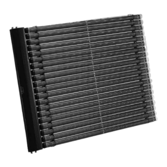
Installation Instructions Vitosol 200-T Model SD2A, 2m Series Model SD2A, 3m Series Vacuum tube solar collector utilizing the direct flow principle to harness solar energy VITOSOL 200-T 5368 538 v1.1 11/2010... -
Page 2: Safety, Installation And Warranty Requirements
The use of Viessmann substructure to the roof. If necessary, the future by service personnel. heat transfer medium “Tyfocor-HTL”... -
Page 3: Table Of Contents
Table of Contents Page Safety Safety, Installation and Warranty Requirements ... . Important Regulatory and Installation Requirements ..General Information About these Instructions ............Product Information . - Page 4 Table of Contents Page Installation on Flat Roofs Overview of System Installation ......... or Freestanding Installation Overview of System Components .
-
Page 5: Important Regulatory And Installation Requirements
Literature applicable to all aspects of site and advise the system the Vitosol: operator/ultimate owner where the - Technical Data Manual literature can be found. Contact - Installation Instructions Viessmann for additional copies. - Start-up, Service and Operating Instructions - System Design Guidelines... -
Page 6: About These Instructions
Product Information Please refer to the Vitosol 200-T Technical Data Manual, for complete technical information and product description. The Technical Data Manuals are available for download at www.viessmann.ca or www.viessmann-us.com. Vitosol 200-T, Model SD2A, 2m Series Vacuum tube collector utilizing the direct flow principle with 20 tubes 22 ft. -
Page 7: Notes On Installation
Although the glass collectors surfaces Filling the solar heating system with should be installed in accordance with are hail-proof, Viessmann Viessmann heat transfer fluid the accepted rules of technology, recommends users to include storm “Tyfocor-HTL” is highly observing all relevant accident coverage in their building insurance. -
Page 8: Overview Of System Installation
Installation on Sloped Roofs (Horizontal Tube Orientation) Overview of System Installation This installation method can be used for any application type. For systems that combine DHW and space heating supplement, this is the preferred installation method for sloped roofs. Panels can be stacked one above the other or side by side. -
Page 9: Overview Of System Components
Installation on Sloped Roofs (Horizontal Tube Orientation) Overview of System Components Sloped roof mounting hardware for horizontal tube orientation Roof bracket Mounting bracket Clamping bracket T-slot bolt Washer Hexagon nut Mounting rail Retaining plate Locking plate Spacer bracket SD2A Collector Mounting rail w/tube holders Connection housing Rubber retainer... -
Page 10: Installation On Shingled Roof
Installation on Sloped Roofs Horizontal Tube Orientation) Installation on Shingled Roof pacer bracket Connection housing Mounting bracket Mounting rail with tube holders Mounting rail Lag bolts Number of collectors Number of tubes 20/20 20/30 30/20 30/30 1439 2149 1439 1439 2149 2149 inches... - Page 11 Installation on Sloped Roofs (Horizontal Tube Orientation) Installation on Shingled Roof (continued) Center the mounting rails, maintaining dimension f=1” / 26mm Note: See page 9 for numbered part description.
- Page 12 Installation on Sloped Roofs (Horizontal Tube Orientation) Installation on Shingled Roof (continued) Always locate an air vent at the highest point in the piping. Attaching roof brackets on shingled roof 1. The roof brackets should be laid out as close as possible to the dimensions shown in the chart on page 9.
-
Page 13: Installing The Mounting Rails
Installation on Sloped Roofs (Horizontal Tube Orientation) Installing the Mounting Rails When several collectors are mounted adjacently, the distance between the installation rails is 1 ” / 26mm (see page 11). 1. Secure the mounting rail to the roof brackets using T-bolts nuts . - Page 14 Installation on Sloped Roofs (Horizontal Tube Orientation) Installing the Mounting Rails (continued) 90º 90º 6. Secure the locking plate at the Note: bottom of the mounting rails with See page 9 for numbered parts tube holders to prevent tube rails description.
-
Page 15: Installing The Connection Housing
Installation on Sloped Roofs (Horizontal Tube Orientation) Installing the Connection Housing Turn T-slot bolt 90° for all installation steps. 1. Position the connection housing onto the mounting rails and click into the retaining plates 2. Align the connection housing. IMPORTANT The tube holders on the installation rails must be in alignment with those in the connection housing;... -
Page 16: Overview Of System Installation
Installation on Sloped Roofs (Vertical Tube Orientation) Overview of System Installation This installation method is best suited for DHW or pool systems with constant loads. IMPORTANT This method is not recommended for applications that combine DHW and space heating supplement or any other application where long periods of stagnation are expected. -
Page 17: Overview Of System Components
Installation on Sloped Roofs (Vertical Tube Orientation) Overview of System Components Sloped roof mounting hardware for vertical tube orientation Roof bracket Mounting bracket Clamping bracket T-slot bolt Washer Hexagon nut Mounting rail Retaining plate SD2A Collector Mounting rail with tube holders Connection housing Rubber retainer Vacuum tube... -
Page 18: Installation On Shingled Roof
Installation on Sloped Roofs (Vertical Tube Orientation) Installation on Shingled Roof 9” / 230mm 17” / 430mm 65” / 1650mm 61.4” / 1560mm Collector Mounting rail Roof bracket Roof sheathing complete with shingles Collector installation rail with tube holders Lag bolts... - Page 19 Installation on Sloped Roofs (Vertical Tube Orientation) Installation on Shingled Roof (continued) 7.4” / 187.5mm Center the mounting rails, maintain dimension f=1” / 26mm Number of collectors Number of tubes 20/20 20/30 30/30 1260 1260 inches 33.5 49.6 33.5 33.5 49.6 1465 1820...
- Page 20 Installation on Sloped Roofs (Vertical Tube Orientation) Installation on Shingled Roof (continued) Always locate an air vent at the highest point in the piping. Attaching roof brackets on shingled roof 1. The roof brackets should be laid out as close as possible to the dimensions shown in the chart on page 19.
-
Page 21: Installing The Mounting Rails
Installation on Sloped Roofs (Vertical Tube Orientation) Installing the Mounting Rails When several collectors are mounted adjacently, the distance between the installation rails is 1 ” / 26mm (see page 19). 1. Secure the mounting rail to the roof brackets using T-bolts washers and nuts... - Page 22 Installation on Sloped Roofs (Vertical Tube Orientation) Installing the Mounting Rails (continued) 17” / 430mm 61.4” / 1560mm center the mounting rails, maintaining 3. Fit clamping brackets onto the dimension f=1”/ 26mm mounting rails ; do not yet tighten the bolts. 4.
-
Page 23: Installing The Connection Housing
Installation on Sloped Roofs Vertical Tube Orientation) Installing the Connection Housing Turn T-slot bolt 90° for all installation steps. 1. Position the connection housing Note: onto the mounting rails and click Please see page 17 for numbered parts into the retaining plates description. -
Page 24: Overview Of System Installation
Installation on Flat Roofs Overview of System Installation This installation method allows for collectors to be mounted on a flat roof with tubes parallel to the roof and can be used for any application. Ballast weights are typically used to hold the collectors in place, however collectors can also be mounted to substructural frames. -
Page 25: Overview Of System Components
Installation on Flat Roofs Overview of System Components Flat roof mounting hardware Rawl plug, S10 Washer Hexagon screw, 8 x 70mm Clamping bracket T-slot bolt Washer Hexagon nut Mounting rail Mounting rail with tube holders Retaining plate Connection housing Vacuum tube Rubber retainer Note: Refer to page 9 for the overview of all... -
Page 26: Mounting Collectors To Ballast Weights
Installation on Flat Roofs Mounting Collectors to Ballast Weights This installation method allows for collectors to be mounted on a flat roof with tubes parallel to the roof. Ballast weights are typically used to hold collectors in place, but collectors can also be mounted to substructure frames. Flat roofs with gravel filling: Clear gravel from position of concrete slabs. -
Page 27: Installing The Mounting Rails
Installation on Flat Roofs Installing the Mounting Rails Center the mounting rails, maintaining dimension d=1” / 26mm Note: Please see page 25 for numbered part description. Legend Ballast Weight A Ballast Weight B Number of collectors Number of tubes 20/20 20/30 30/20 30/30... - Page 28 Installation on Flat Roofs Installing the Mounting Rails (continued) 1. Position ballast weights on a solid surface on protective mats. 2. Attach clamping brackets ballast weights ; do not yet tighten the bolts. 3. Click the mounting rails into the clamping brackets , align and tighten.
-
Page 29: Installing The Connection Housing
Installation on Flat Roofs Installing the Connection Housing Turn T-slot bolt 90° for all installation steps. 1. Position the connection housing Note: onto the mounting rails and click Please see page 25 for numbered parts into the retaining plates description. 2. - Page 30 Freestanding Installation Overview of System Installation This installation method is best suited for DHW or pool systems with constant loads. IMPORTANT This method is not recommended for applications that combine DHW and space heating supplement or any application where long periods of stagnation are expected.
-
Page 31: Overview Of System Components
Installation on Flat Roofs or Freestanding Installation Overview of System Components Flat roof or freestanding mounting hardware Rawl plug (field supplied) Washer (field supplied) Hexagon screw (field supplied) Hex bolt M8 x 20 Washer Ø 8.4 mm Hex nut M8 Cross brace Collector support Adjustable upper support... -
Page 32: Determining The Collector Row Distance "Z
Installation on Flat Roofs or Freestanding Installation Determining the Collector Row Distance “z” IMPORTANT When installing several collectors in series, maintain a distance of “z”. Example: Model SD2A Toronto is located at approx. 43° latitude. 1. Determine the angle of the sun β. This should be chosen so that the midday sun December 21 falls on the second row of collectors without... -
Page 33: Assembling The Support Frame
Installation on Flat Roofs or Freestanding Installation Assembling the Support Frame 1. Position substructure base or suitable support rails on a solid foundation, in accordance with the dimensions in the table below. Collector Combination distance distance between between rails collectors / 2m 35.4/35.4 24.4... - Page 34 Installation on Flat Roofs or Freestanding Installation Assembling the Support Frame (continued) 1. Secure the adjustable upper support to the collector support shown. 2. Secure the adjustable upper support and lower support to the desired angle of inclination. 3. Assemble the clamping brackets (two as shown and one at the top) to the collector support as shown...
- Page 35 Installation on Flat Roofs or Freestanding Installation Assembling the Support Frame 1. Install both mounting rails to the clamping brackets as shown, then tighten. 2. Install the connection housing the retaining plates and clamping brackets as shown, then tighten. IMPORTANT The tube holders on the installation rails must be in alignment with those in the connection housing;...
-
Page 36: Overview Of System Installation
Installation on a Wall Overview of System Installation This installation method can be used for any application type. Panels can be stacked one above the other or side by side. Note: Refer to page 43 for supply and return piping configurations. For this installation method the general connection set with air-vented u-pipe must be used. -
Page 37: Overview Of System Components
Installation on a Wall Overview of System Components Legend: Rawl plug, S10 Washer Hexagon screw, 8x70mm Mounting bracket T-slot bolt Washer Hexagon nut Mounting rail Mounting rail with tube holders Retaining plate Mounting plate Connection housing Vacuum tube Rubber retainer Note: Refer to page 9 for the overview of all hydronic connection accessories. -
Page 38: Installing The Mounting Rails
Installation on a Wall Installing the Mounting Rails Center the mounting rails, maintaining dimension d=1” / 26mm Number of collectors Number of tubes 20/20 20/30 30/20 30/30 1260 1260 1260 inches 33.5 49.6 33.5 33.5 49.6 49.6 1465 1615 2025 2175 ––... - Page 39 Installation on a Wall Installing the Mounting Rails (continued) Turn T-slot bolts 90° for all installation steps. 1. Attach the mounting brackets the wall according to the dimensions 90º in the diagram on the previous page. 2. Align the mounting rails secure to the mounting brackets 65”...
- Page 40 Installation on a Wall Installing the Mounting Rails (continued) 7. Secure the mounting plate at the bottom of the mounting rails with the tube holders 1” / 26mm Note: See page 37 for numbered parts description.
-
Page 41: Installing The Connection Housing
Installation on a Wall Installing the Connection Housing Turn T-slot bolt 90° for all installation steps. 1. Position the connection housing onto the mounting rails and click into the retaining plates 2. Align the connection housing. IMPORTANT The tube holders on the installation rails must be in alignment with those in the connection housing;... -
Page 42: Joining The Connection Housings
Hydronic Connections Joining the Connection Housings 1.9” / CAUTION 47mm The connection pipes must not be damaged or dirty. All plug-in connections (O-ring seal) on the collectors may only be lubricated with the special lubricant grease supplied in the connection kit. The connections must not come into contact with conventional oils, greases or other lubricants. -
Page 43: Installing The General Connection Kit And Collector Temperature Sensor
Hydronic Connections Installing the General Connection Kit and the Collector Temperature Sensor Installation examples (hydronic connection) Vitosol 200-T, Model SD2A Note collector area (150 tubes) can be linked up in a series to form a single array. Up to 15m Single-sided connection from Connection on both 2 or more... - Page 44 Supply all installations with tubes mounted horizontally. 8. Insert the support sleeves into the Viessmann supplied 3/4” x metric copper adaptors. Connect the copper adaptors to the pipework of the solar heating circuit. 9. Check the system pressure and test for leaks (only after installing tubes).
-
Page 45: Installing The Vacuum Tubes
Hydronic Connections Installing the Vacuum Tubes CAUTION The vacuum tubes can become hot or break if insufficient care is taken. To avoid the possibility of skin burns, it is recommended to install the tubes on a cloudy day, or in the evening when direct sun is no longer shining on the collector location. -
Page 46: Removing The Vacuum Tubes (If Required)
Hydronic Connections Removing the Vacuum Tubes (if required) IMPORTANT System fluid pressure must be reduced to zero prior to removing tubes. Isolate individual collectors if possible. For the safe removal of the tubes, we recommend the opening of the housing lid. -
Page 47: Collector Supply And Return Piping
Hydronic Connections Collector Supply and Return Piping For the piping connecting the CAUTION collectors to the Solar Divicon pumping station, Viessmann Do not use galvanized pipes, recommends the use of commercial galvanized fittings or graphitized copper pipe and bronze fittings, or gaskets, or any type of plastic pipes. -
Page 48: System Installation
H Fill the solar heating system with Viessmann heat transfer medium ”Tyfocor-HTL”. The “Tyfocor-HTL” is supplied as a premixed glycol/water solution and must not be mixed. The... -
Page 49: Initial Start-Up
Appendix Initial Start-up The collector circuit must be protected in such a way that at the highest possible collector temperature (shutdown temperature) no heat transfer fluid can escape from the safety valve, or the air vent. This is achieved by the appropriate sizing of the expansion tank and matching of the system pressure. -
Page 50: Post-Installation Information
Appendix Post-Installation Information... Checklist j Has the solar circuit been installed in accordance with the circuit diagram and all relevant standards? j Have the collectors been installed with a slight upward gradient towards the piping side? j Have the supply and return connections been carried out and pressure tested? j Have the electrical connections been... - Page 51 5368 538 v1.1...
- Page 52 Viessmann Manufacturing Company (U.S.) Inc. Viessmann Manufacturing Company Inc. 45 Access Road 750 McMurray Road Warwick, Rhode Island 02886 Waterloo, Ontario N2V 2G5 Canada 1-800-288-0667 Fax (401) 732-0590 1-800-387-7373 Fax (519) 885-0887 www.viessmann-us.com info@viessmann-us.com www.viessmann.ca info@viessmann.ca...
Need help?
Do you have a question about the VITOSOL 200-T SD2A 2m2 Series and is the answer not in the manual?
Questions and answers