Table of Contents
Advertisement
Quick Links
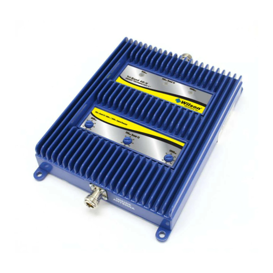
800 /(1700-2100)/ 1900 MHz
In-Building Wireless
Smart Technology
Signal Booster
Contents:
Antenna Options & Accessories . . . . . . . . . . . . . . . . . . . 1
Quick Install Overview . . . . . . . . . . . . . . . . . . . . . . . . . . . 2
Installation Diagram . . . . . . . . . . . . . . . . . . . . . . . . . . . . . 3
Before Getting Started . . . . . . . . . . . . . . . . . . . . . . . . . . . 4
Outside Antenna Installation . . . . . . . . . . . . . . . . . . . . . . 5
Finding the Strongest Signal . . . . . . . . . . . . . . . . . . . . . . 6
Installing the Inside Antenna . . . . . . . . . . . . . . . . . . . . . . 8
Installing a Wilson Electronics Signal Booster . . . . . . . . . 9
Powering up a Wilson Electronics Signal Booster . . . . . . 9
Understanding the Signal Booster Lights . . . . . . . . . . . 10
Warnings and Recommendations . . . . . . . . . . . . . . . . . 12
Guarantee & Warranty . . . . . . . . . . . . . . . . . . . . . . . . . . 14
Specifications . . . . . . . . . . . . . . . . . . . . . . . . . Back Cover
Appearance of device and accessories may vary .
Note: This manual contains important safety and operating information . Please read and
follow the instructions in this manual . Failure to do so could be hazardous and result in
damage to your Signal Booster .
™
Advertisement
Table of Contents

Related Manuals for Wilson Electronics Tri-Band 4G-C


Summary of Contents for Wilson Electronics Tri-Band 4G-C
-
Page 1: Table Of Contents
Installing the Inside Antenna . . . . . . . . . . . . . . . . . . . . . . 8 Installing a Wilson Electronics Signal Booster . . . . . . . . . 9 Powering up a Wilson Electronics Signal Booster . -
Page 2: Antenna Options & Accessories
. They amplify a weak or shadowed signal in mobile, marine, M2M and in-building applications . When using a Wilson Electronics Signal Booster in conjunction with Wilson Electronics antennas, the Outside Antenna will collect the cell tower signal and send it through the cable to the Signal Booster . -
Page 3: Quick Install Overview
Quick Install Overview See Installation Diagram on page 3 . Contact Wilson Electronics Technical Support Team with any questions at 866-294-1660 . Select a location to install the Signal Booster that is away from excessive heat, direct sunlight, moisture and has proper ventilation . Do not place the Signal Booster in an air-tight enclosure . -
Page 4: Installation Diagram
(sold separately). Make sure the protector is installed in line between the Outside Antenna and the Signal Booster. Power Supply Typical Installation Contact Wilson Electronics Technical Support Team with any questions at 866-294-1660 or email: tech@wilsonelectronics.com. Hours: 7 am to 6 pm MST. -
Page 5: Before Getting Started
Before Getting Started This guide will help you properly install your Wilson Electronics Signal Booster . It is important to read through all of the installation steps for your particular application prior to installing any equipment. Read through the instructions, visualize where all the equipment will need to be installed and do a soft installation before mounting any equipment . -
Page 6: Outside Antenna Installation
Signal Booster (see Figures 1 & 2 on page 10) . Contact Wilson Electronics Technical Support Team with any questions at 866-294-1660 or email: tech@wilsonelectronics.com. Hours: 7 am to 6 pm MST. -
Page 7: Finding The Strongest Signal
. This allows you to read the signal strength from the cell tower . It is preferable to have Contact Wilson Electronics Technical Support Team with any questions at 866-294-1660 or email: tech@wilsonelectronics.com. Hours: 7 am to 6 pm MST. - Page 8 . Contact Wilson Electronics Technical Support Team with any questions at 866-294-1660 or email: tech@wilsonelectronics.com. Hours: 7 am to 6 pm MST.
-
Page 9: Installing The Inside Antenna
Optional Wide Band Splitter Options: (sold separately) Inside Antenna (sold separately– multiple mounting options) 2-way 3-way 4-way (859957) (859980) (859981) Contact Wilson Electronics Technical Support Team with any questions at 866-294-1660 or email: tech@wilsonelectronics.com. Hours: 7 am to 6 pm MST. -
Page 10: Installing A Wilson Electronics Signal Booster
5 . Using multiple Signal Boosters in one installation could cause interference to the cell tower (except for the In-Line Signal Booster) . 6 . Contact Wilson Electronics Technical Support Team with any questions at 866-294-1660 or email tech@wilsonelectronics .com . Technical Support hours are 7 am to 6 pm MST . -
Page 11: Understanding The Signal Booster Lights
(cell tower) overload . The Signal Booster has reduced the gain to prevent the disruption of cell towers . If the light is Contact Wilson Electronics Technical Support Team with any questions at 866-294-1660 or email: tech@wilsonelectronics.com. Hours: 7 am to 6 pm MST. - Page 12 . Adjust the Gain to minimum and plug the booster back in . You should now have a green light, if not, call Wilson Electronics Technical Support . Next, unplug the booster, reconnect the coax cables to the booster and tighten all connections, and plug the booster back in .
-
Page 13: Warnings And Recommendations
. Changes or modifications not expressly approved by Wilson Electronics could void the authority to operate this equipment . Contact Wilson Electronics Technical Support Team with any questions at 866-294-1660... - Page 14 About Wilson Electronics Wilson Electronics, Inc . has been a leader in the wireless communications industry for over 40 years . The company designs and manufactures Signal Boosters, Antennas and related components that significantly improve cellular phone signal reception and transmission in a wide variety of applications, both mobile (marine, RV, vehicles) and in-building (home, office, M2M) .
-
Page 15: Guarantee & Warranty
. However, no responsibility is assumed by Wilson Electronics, Inc . for any business or personal losses arising from its use, or for any infringements of patents or other rights of third parties that may result from its use . -
Page 16: Specifications
Signal Booster Specifications Tri-Band AWS Model Number 272770 Antenna connectors N-Female Antenna impedance 50 Ohms Dimensions 8 .875 x 6 .0 x 1 .5 inch (22 .5 x 15 .2 x 3 .8 cm) Weight 2 .8 lbs (1 .270 kg) Frequency 1710-2155 MHz / 824-894 MHz / 1850-1990 MHz 1700-2100 MHz...
Need help?
Do you have a question about the Tri-Band 4G-C and is the answer not in the manual?
Questions and answers