Wilson Electronics weBoost Drive Reach RV Installation Manual
Cell signal booster
Hide thumbs
Also See for weBoost Drive Reach RV:
- Installation overview (2 pages) ,
- Installation manual (27 pages)
Table of Contents
Advertisement
Advertisement
Table of Contents

Related Manuals for Wilson Electronics weBoost Drive Reach RV


Summary of Contents for Wilson Electronics weBoost Drive Reach RV
- Page 1 Installation Guide ® Drive Reach RV Cell Signal Booster...
-
Page 2: Table Of Contents
Index Package Contents ............1 STEP 1 Mount Outside Antenna &... -
Page 3: Package Contents
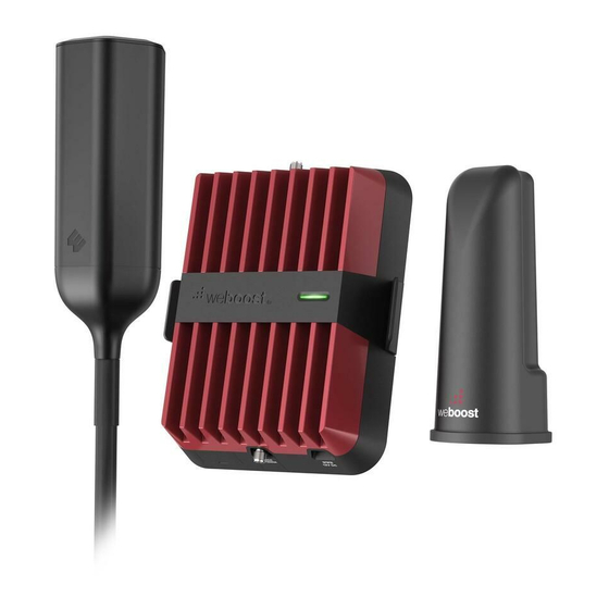
Package Contents Drive Reach Outside Inside Power 13 in. Mast Extension, Signal Booster Antenna Antenna Supply Side-Exit Adapter, & Bracket Spring, L-Bracket Mount & Thread Lock Pack... -
Page 4: Step 1 Mount Outside Antenna & Route Cable
STEP 1 Mount Outside common outside antenna location Antenna & Route Cable Determine where you want the Outside Antenna on your RV. Mount Outside Antenna to a ladder or pole so that the entire Outside Antenna is above the roof line of the RV and clear of other metal obstructions. - Page 5 (STEP 1 cont.) To assemble the antenna, insert cable through Mast then through Side Exit Adapter. NOTE: Antenna Spring can be used optionally. 13 in. 13 in. mast mast cable from antenna Side Exit run cable Adapter through Mast Extension(s) Mast Antenna Spring Extension...
- Page 6 (STEP 1 cont.) Verify the antenna is the correct height, if Drive RV so, use thread locker (provided) to thread Antenna points and screw into place. NOTE: When adding the side exit adapter hold the antenna vertically and screw the adapter from the bottom up.
- Page 7 (STEP 1 cont.) Mount Outside Antenna. L-Bracket Side Exit Adapter Mount and hardware is provided to mount to ladder or pole. If installing add thread with Spring, the Side Exit Adapter must locker be used. Then route 25’ RG-58 cable Spring from inside RV to Outside Antenna.
-
Page 8: Step 2 Connect Cable Outside Antenna
STEP 2 Connect Cable to Outside Antenna After routing the RG-58 Cable into the Cable from Outside Antenna RV, connect the cable to the Outside Antenna. RG-58 Cable STEP 3 Inside Antenna Location & Connect Cable Intside Antenna Place Inside Antenna where stronger signal is desired in the RV. -
Page 9: Step 4 Booster Location & Connect Cables
STEP 4 Booster Location & from Outside Antenna Connect Cables Find a location to place the Drive Reach Booster and secure it with provided bracket. Connect cable from Outside Antenna to labeled booster port and connect cable from Inside Antenna to labeled booster port. from Inside Antenna STEP 5 Connect Power Supply to Booster... -
Page 10: Booster Light Patterns
Booster Light Patterns SOLID GREEN This indicates that your Drive Reach Booster is functioning properly and there are no issues with installation. SOLID RED Band has shuto . This is due to a feedback loop condition called oscillation. This is a built in safety feature that causes a band to shut o to prevent harmful interference with a nearby cell tower. - Page 11 (Booster Light Patterns cont.) NOTE: The Signal Booster can be reset by disconnecting and reconnecting the power supply. After troubleshooting you must initiate a new power cycle by disconnecting and then reconnecting power to the Booster.
-
Page 12: Troubleshooting
Troubleshooting FIXING BLINKING OR RED LIGHT ISSUES This section is only applicable if the booster is red or blinking red and you are not experiencing the desired signal boost. 1 Unplug the Booster’s power supply. Relocate the inside and outside antenna further from each other. The objective is to increase the separation distance between them, so that they will not create this feedback condition discussed before. - Page 13 (Troubleshooting cont.) FREQUENTLY ASKED QUESTIONS How can I contact customer support? Customer Support can be reached Monday thru Friday by calling 866.294.1660, or through our support site at support.weboost.com. Why do I need to create distance between the booster and the antenna? Antennas connected to a booster create spheres of signal.
-
Page 14: Safety Guidelines
Safety Guidelines Use only the power supply provided in this package. Use of a non-weBoost product may damage your equipment. Connecting this signal booster directly to the cell phone with use of an adapter will damage the cell phone. RF Safety Warning: Any antenna used with this device must be located at least 8 inches from all persons. AWS Warning: The Outside Antenna must be installed no higher than 10 meters (31’9”) above ground. - Page 15 (Safety Guidelines cont.) FOR MORE INFORMATION ON REGISTERING YOUR SIGNAL BOOSTER WITH YOUR WIRELESS PROVIDER, PLEASE SEE BELOW: Sprint: http://www.sprint.com/en/legal/signal-boosters.html?=search:booster T-Mobile/MetroPCS: https://support.t-mobile.com/docs/DOC-9827 Verizon Wireless: http://www.verizonwireless.com/wcms/consumer/register-signal-booster.html AT&T: https://securec45.securewebsession.com/attsignalbooster.com/ U.S. Cellular: http://www.uscellular.com/uscellular/support/fcc-booster-registration.jsp...
- Page 16 Antenna Info The following accessories are certified by the FCC to be used with the Drive Reach Booster. MOBILE INSIDE ANTENNA KIT OPTIONS Kit # Coax Type Ln(ft) Antenna Type 314419 LMR-100 4G Slim Low Profile SMB MOBILE OUTSIDE ANTENNA KIT OPTIONS Kit # Coax Type Ln(ft)
-
Page 17: Specifications
Specifications Drive Reach Cell Signal Booster 460054 Model PWO460054 Connectors SMB-Jack 50 Ohms Antenna Impedence Frequency 698-716 MHz, 728-756 MHz, 777-787 MHz, 824-894 MHz, 1850-1995 MHz, 1710-1755/2110-2155 MHz Power output for single cell 700 MHz B12/17 700 MHz B13 800 MHz B5 1700 MHz B4 1900 MHz B2 phone (Uplink) dBm... -
Page 18: Warranty
Returned Material Authorization (RMA) number supplied by Wilson Electronics. Wilson Electronics shall, at its option, either repair or replace the product. Wilson Electronics will pay for delivery of the repaired or replaced product back to the original consumer if located within the continental U.S. - Page 19 Notes 1.866.294.1660 www.wilsonelectronics.com support@wilsonelectronics.com...
- Page 20 3301 East Deseret Drive, St. George, UT 866.294.1660 www.wilsonelectronics.com support@wilsonelectronics.com Copyright © 2020 Wilson Electronics. All rights reserved. Wilson Electronics products covered by U.S. patent(s) and pending application(s) For patents go to: weboost.com/us/patents NOT AFFILIATED WITH WILSON ANTENNA GDE000290_Rev01_09.21.20...
Need help?
Do you have a question about the weBoost Drive Reach RV and is the answer not in the manual?
Questions and answers