Kipor Sinemaster IG3000 Operation Manual
Hide thumbs
Also See for Sinemaster IG3000:
- Operation manuals (42 pages) ,
- Operation manual (41 pages) ,
- Owner's manual (40 pages)
Table of Contents
Advertisement
Advertisement
Table of Contents

Related Manuals for Kipor Sinemaster IG3000


Summary of Contents for Kipor Sinemaster IG3000
- Page 2 PREFACE Thank you for purchasing a Kipor Generator. This manual covers the operation and preventive maintenance of the IG3000 generator with EPA and r California Air Resources Board (CARB) certification if so designated. All information in this publication is based on the latest product information available at the time of printing.
- Page 3 The portable generator is not meant to be used as a permanent back-up power system for the home. A permanently installed stationary generator is designed to be safely used for this specific purpose. Indicates a strong possibility of severe personal injury or death if instructions are not followed.
-
Page 4: Table Of Contents
CONTENTS 1. SAFETY INSTRUCTIONS ·································································································· 1 2. COMPONENT LOCATIONS ······························································································· 3 2.1 Outside View·················································································································· 3 2.2 Control Panel ················································································································· 4 2.3 Serial Number Location ································································································· 4 3. PRE-OPERATION CHECK································································································· 5 3.1 Engine Oil ······················································································································ 5 3.1 Fuel ································································································································ 6 3.3 Air Cleaner····················································································································· 7 4. - Page 5 11. WIRING DIAGRAM ········································································································· 28 12. WHEEL KIT INSTALLATION ·························································································· 29 13. WARRANTY ···················································································································· 30 13.1 Limited Warranty- Kipor Power Products ································································ 30 13.2 Emission Control Warranty ······················································································ 31 13.2 California Emissions Control Warranty Statement ·················································· 33 14. EMISSION CONTROL SYSTEM ···················································································· 34...
-
Page 6: Safety Instructions
1. SAFETY INSTRUCTIONS Our generators are designed to give safe and dependable service if operated according to these instructions. Read and understand the owner's manual before operating the generator. Failure to do so could result in personal injury or equipment damage. Exhaust gas contains poisonous carbon monoxide. - Page 7 To ensure safe operation: Gasoline is extremely flammable and explosive under certain conditions. Refuel in a well ventilated area with the engine stopped. Keep away from smoking materials, sparks and other sources of combustion when refueling the generator. Always refuel in a well-ventilated location.
-
Page 8: Component Locations
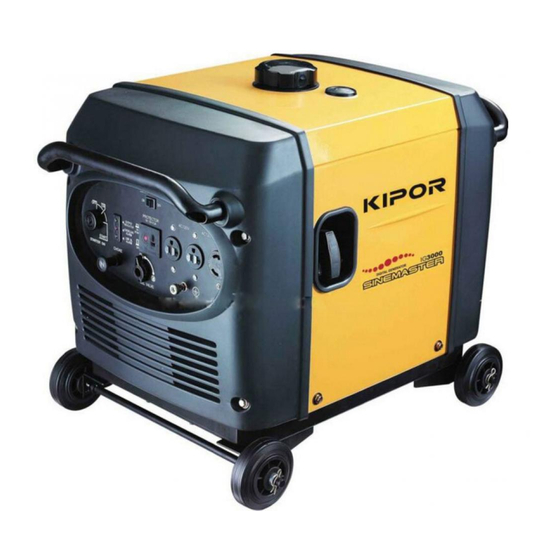
2. COMPONENT LOCATIONS 2.1 Outside view Carbon Canister Spark plug Oil dipstick Control panel Service door Air intake Battery Air filter Fuel level indicator Fuel filler cap Air quality index Starter grip Air exhaust Muffler warning... -
Page 9: Control Panel
2.2 Control panel Overload protection device SMART throttle switch AC receptacle DC receptacle Overload Reset Switch Ignition Module Engine switch Ground terminal Choke knob Fuel valve lever 2.3 Serial Number and Bar Code Location: The engine serial number is stamped on the engine block to the left of the oil drain plug. In most cases the battery will have to be removed to view it clearly. -
Page 10: Pre-Operation Check
3. PRE-OPERATION CHECK Be sure to check the generator on a level surface with the engine stopped. Under no circumstances can this generator be installed in an enclosed compartment. 3.1 Engine Oil Level Using non-detergent oil or 2-stroke engine oil could shorten the engine's service life. -
Page 11: Fuel
Running the engine with insufficient oil can cause serious engine damage. The Low Oil Alarm System will automatically stop the engine before the oil level falls below a safe limit. However, to avoid the inconvenience of an unexpected shutdown, it is still advisable to visually inspect the oil level regularly. -
Page 12: Air Cleaner
Gasoline containing alternate fuels: If you decide to use a gasoline containing ethanol, be sure its octane rating is no lower than the specification. Do not use a blend that contains more than 10% ethanol. Do not use any gasoline containing methanol. -
Page 13: Starting The Engine
4. STARTING THE ENGINE When starting the generator after adding fuel for the first time or after long term storage, or after running out of fuel, turn the fuel valve lever to the "ON" position, then wait for 10 to 20 seconds before starting the engine. - Page 14 4.1(c) Insert the engine key and turn the engine switch to ON position. Engine switch Fig.8 4.1(d) Electric Start: turn the engine switch to the START until the engine has started. Do not operate the starter for more than 10 seconds. Manual Start: pull the starter grip lightly until resistance is felt then pull the starter grip briskly toward the arrow as shown below.
-
Page 15: High Altitude Operation
4.1(e) Push the choke knob in to the OPEN position as the engine warms up. Choke knob Fig.10 4.2 High altitude operation At high altitude, the standard carburetor air-fuel mixture will be excessively rich Performance will decrease, and fuel consumption will increase. High altitude performance can be improved by installing a smaller diameter main fuel jet in the carburetor. -
Page 16: Warnings And Cautions
5.1 Warnings and Cautions To prevent electrical shock from faulty appliances, the generator should be grounded. Connect a length of heavy cable between the generator's ground terminal and an external ground source. Connections for standby power to a building's electrical system must be made by a qualified electrician and must comply with all applicable laws and electrical codes. -
Page 17: Ac Power Applications
a 12 gauge cord to safely power any tool. Keep the generator away from other electric cables or wires such as commercial power supply lines. You may use DC receptacle when using AC supply. 5.2 AC Power Applications 1. Start the engine and make sure the green output indicator light comes on. 2. -
Page 18: Overload Reset Switch
be exceeded, the circuit protection device will activate and cut all current to the receptacle. This will be indicated by the push button popping out. Reduce the load to the receptacle and reset the circuit protector by pushing in the button. Before connecting an appliance to the generator, check that it is in good order, and that its electrical rating does not exceed that of the generator. -
Page 19: Air Conditioning Operation
When the SMART throttle is placed in the on position, engine speed is kept at idle automatically when the electrical load is disconnected and returns to the proper speed required by the electrical load when the load is reconnected. The engine speed varies according to the amount of load applied to the generator. - Page 20 The DC receptacle may be used for charging 12 volt automotive-type batteries only. It is not designed to operate DC motors. Output voltage is 15-30V. DC output will vary according to the position of the Smart throttle switch. a. Connect the charging cable to the DC receptacle of the generator and then to the battery terminals. To prevent the possibility of creating sparks near the battery, connect the charging cable first to the generator then to the battery.
-
Page 21: Low Oil Alarm System
or transformer. b. Start the generator. The DC receptacle may be used while the AC power is in use. The DC receptacle is protected from an overload with a fuse. If the DC circuit is overloaded, the 5 amp fuse will blow and power to the DC receptacle will cease. The red light on the DC panel will illuminate. -
Page 22: Stopping The Engine
6. STOPPING THE ENGINE 6.1 Normal Shutdown 1. Switch off the connected equipment and disconnect from the generator. 2. Turn off the engine switch. 3. Turn the fuel valve lever to the OFF position. 6.2 Emergency Stop Turn the start switch to the OFF position. Continually stopping the generator with a load applied can lead to damage of the control module. -
Page 23: Maintenance
Carbon monoxide is a poisonous gas. The emission of fuel vapors is a source of pollution as well. The Kipor generator engine utilizes a precise air-fuel ratio and emission control system to reduce the emissions of carbon monoxide, NO , hydrocarbons, and evaporative fuel emissions. - Page 24 You can trust the replacement parts supplied by Kipor have been manufactured to the same production standard as the original parts. The use of replacement parts or accessories which are not designed by Kipor may affect the engine emission performance.
-
Page 25: Maintenance Schedule
(2) Service more frequently when used in dusty conditions. (3) These items should be serviced by an authorized KIPOR service center unless the owner has the proper tools and is mechanically proficient. Refer to the KIPOR Generator and Engine shop manuals. -
Page 26: Air Cleaner Service
Oil drain bolt Oil dipstick 1. Open the left side maintenance cover. 2. Remove the oil dipstick. 3. Remove the drain bolt and drain the oil. There is a rubber plug in the bottom of the generator pan that can be removed to facilitate draining the oil. The generator will have to be raised off the ground and supported while the oil drains. -
Page 27: Spark Plug Service
1. Open the service door. 2. Unsnap the clips and remove the air cleaner cover. 3. If the paper element is dirty or torn, replace it with a new one. Do not attempt to clean the element. 5. Reinstall the air cleaner cover. 6. -
Page 28: Spark Arrestor Maintenance
7. Install the spark plug carefully, by hand, to avoid cross-threading. 8. After a new spark plug has been seated by hand, it should be tightened 1/2 turn with a wrench to compress the sealing washer. If a used plug is being reinstalled, it should only require 1/8 to 1/4 turn after being seated. - Page 29 necessary.
-
Page 30: Transporting/Storage
8. TRANSPORTING/STORAGE 8.1 Transporting When transporting the generator, turn the fuel valve lever OFF and keep the generator level to prevent fluid spillage. Fuel vapors or spilled fuel may ignite. Transporting the generator with gasoline in the fuel tank is prohibited. 8.2 Extended Storage: 1. -
Page 31: Troubleshooting
1) Turn off the fuel valve and loosen the drain screw. 2) Fuel should flow from the drain when the fuel If the engine still does not start, take valve is turned on. the generator to an authorized Kipor service center. - Page 32 AC Appliance does not operate: Is the output indicator light ON? Is the overload indicator Take the generator to a Kipor service center. light ON? Check the electrical appliance or Take generator equipment for any defects. authorized KIPOR service center.
-
Page 33: Specifications
10. SPECIFICATIONS Model IG3000 Type Inverter Rated Voltage Frequency 60 HZ Maximum Output 3000W, 25A Rated Output 2800W, 23.3A DC Output 12V@5.0A Engine Model KG205 Engine Type 4 Stroke, overhead valve, single cylinder Displacement 12.0 cu in (196 cc) Compression Ratio 8.5:1... -
Page 34: Wiring Diagram
11. WIRING DIAGRAM... -
Page 35: Wheel Kit
12. WHEEL KIT The unit comes with the rubber mounting feet installed. If you wish to install the wheel kit, please perform the following procedure. Wheel Kit . Axle assembly (1) 2. Locking swivel wheel (2) 3. Bolt M8X16 (4) 4. -
Page 36: Warranty
Kipor or its distributor reserves the right to repair or replace these parts at its option. The return of defective parts may be requested.. -
Page 37: Emission Control Warranty
You are required to bring your generator to an authorized Kipor generator dealer for repairs as soon as a problem exists. For emissions warranty service, contact your nearest dealer or contact the national service center: Phone (503) 443-0199 or E-mail: service@kiporpowersystems.com... - Page 38 Kipor Generator Owner’s Manual. Additionally, coverage may be denied for the use of add-on parts, modified parts, or parts that are not equivalent to original Kipor generator parts in performance and durability.
-
Page 39: California Emissions Control Warranty Statement
2. As the SORE owner, you should however be aware that Kipor may deny your warranty coverage if your SORE or a part has failed due to abuse, neglect, improper maintenance or unapproved modifications. -
Page 40: Emission Control System
3. A catalyst is built into the muffler to further treat the engine exhaust. 4. A secondary air injection valve adds combustion air to ignite unburned fuel in the exhaust. Contact your authorized Kipor service center to obtain the correct replacement parts and service on this system. - Page 41 Fuel System...
- Page 42 Generator Frame Canister Service Door Side Carbon Canister Location Secondary Valve Gasket Bolt Muffler with Catalyst Gasket Spark Arrestor Connection to exhaust manifold Exhaust System...
Need help?
Do you have a question about the Sinemaster IG3000 and is the answer not in the manual?
Questions and answers