Table of Contents
Advertisement
Quick Links
Advertisement
Table of Contents

Subscribe to Our Youtube Channel
Related Manuals for Insportline IN 5561


Summary of Contents for Insportline IN 5561
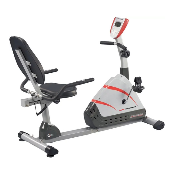
- Page 1 USER MANUAL – EN IN 5561 Recumbent inSPORTline Rapid RMB IMPORTANT: Read all instructions carefully before using this product. Retain this owner’s manual for future reference. The specifications of this product may vary from this photo and are subject to change...
-
Page 2: Table Of Contents
CONTENTS IMPORTANT SAFETY INSTRUCTIONS ......................3 PARTS LIST ................................4 HARDWARE LIST ............................6 TOOLS ................................6 OVERVIEW DRAWING ............................7 ASSEMBLY INSTRUCTIONS ..........................8 CORRECT WORKOUT POSITION ........................21 HOW TO MOVE THE RECUMBENT BIKE ...................... 21 MOUNTING AND DISMOUNTING THE RECUMBENT BIKE ..............22 OPERATING THE COMPUTER ......................... -
Page 3: Important Safety Instructions
IMPORTANT SAFETY INSTRUCTIONS Basic precautions should always be followed, including the following important safety instructions when using this equipment. Read all instructions before using this equipment. 1. Read all instructions and follow it carefully before using this equipment. Make sure the equipment is properly assembled and tightened before use. -
Page 4: Parts List
PARTS LIST Description Right Front Stabilizer End Cap Ø60x1.5 Front Stabilizer Ø60x1.5x330 Cap Nut M8 Curve Washer Ø8 Screw ST4.2x25 Bolt M8x70 Left Front Stabilizer End Cap Ø60x1.5 Cover Cap Ø50xØ25x10 Pan Head Phillips Self Drilling Screw ST4.2x25 Right Cover Belt 350J6 Right Foot Pedal YH-30X Crank Ø240... - Page 5 Washer Ø8 Bolt M8x20 Left Rear Stabilizer End Cap Idle Wheel Bracket Nylon Nut M8 Front Handlebar Post Cover Spring Bearing 6000ZZ Middle Section Hand Pulse Sensor Wire L=1000mm Bolt M8x30 Rear Main Frame Seat Cushion Back Cushion Bolt M6x15 Washer Ø6 Backrest and Seat Support Bracket End Cap 23x53x1.5 Seat Sliding Tube 53x23x2.0...
-
Page 6: Hardware List
Washer Ø40xØ24x3 Nut M10x1 Adjustable Bolt M6x36 Screw ST2.9x12 Big Curve Washer Ø8 Spring Washer Ø6 U Bracket Washer Ø10xØ14x1 Washer Ø12xØ6x1 Bolt M6x10 Water Bottle Holder Bolt M5x15 HARDWARE LIST TOOLS... -
Page 7: Overview Drawing
OVERVIEW DRAWING... -
Page 8: Assembly Instructions
ASSEMBLY INSTRUCTIONS STEP 1 Remove two M8x30 Bolts (45), four M8x15 Bolts (72), and six Ø8 Washers (36) from the Rear Main Frame (46). Remove bolts with the Allen Wrench provided. - Page 9 STEP 2 Connect the Middle Section Hand Pulse Sensor Wires (44) from the Rear Main Frame (46) to the Extension Hand Pulse Sensor Wires (70) from the Front Main Frame (21). Attach the Rear Main Frame (46) into the Front Main Frame (21) with two M8x30 Bolts (45), four M8x15 Bolts (72), and six Ø8 Washers (36) that were removed.
- Page 10 STEP 3 HARDWARE: Position the Front Stabilizer (2) in front of the Front Main Frame (21) and align bolt holes. Attach the Front Stabilizer (2) onto the front curve of the Front Main Frame (21) with two M8x70 Bolts (6), two Ø8 Big Curve Washers (77), and two M8 Cap Nuts (3).
- Page 11 STEP 4 HARDWARE: Insert both M10 Adjustable Levelers (67) into the threaded holes on the underside of the Rear Stabilizer (64). Twist the M10 Adjustable Levelers (67) to adjust height, then tighten the M10 Nuts (66) after adjustment. Position the Rear Stabilizer (64) behind the Rear Main Frame (46) and align bolt holes. Attach the Rear Stabilizer (64) onto the rear curve of the Rear Main Frame (46) with two M8x70 Bolts (6), two Ø8 Big Curve Washers (77), and two M8 Cap Nuts (3).
- Page 12 STEP 5 Remove one Ø8 Curve Washer (4), one M8x15 Bolt (72), four M8x10 Bolts (35) and four Ø8 Washers (36) from the Front Main Frame (21). Remove bolts with the Allen Wrench provided.
- Page 13 STEP 6 Slide the Front Handlebar Post Cover (41) up to the Front Handlebar Post (34). Insert the Tension Cable (31) through into the bottom hole of Front Handlebar Post (34) and pull it out from the square hole of Front Handlebar Post (34). Connect the Sensor Wire (71) and Extension Hand Pulse Sensor Wires (70) from the Front Main Frame (21) to the Extension Sensor Wire (26) and Extension Wires (27) from the Front Handlebar Post (34).
- Page 14 STEP 7 Insert the Front Handlebar Post (34) onto the tube of the Front Main Frame (21) and secure with one Ø8 Curve Washer (4), one M8x15 Bolt (72), four M8x10 Bolts (35) and four Ø8 Washers (36) that were removed. Tighten bolts with the Allen Wrench provided.
- Page 15 STEP 8 Remove one M5x20 Bolt (33) and one Ø5 Washer (32) from the Tension Control Knob (30). Remove bolt with the Multi Hex Tool with Phillips Screwdriver provided. Put the cable end of resistance cable of Tension Control Knob (30) into the cable lock of Tension Cable (31), see Figure A.
- Page 16 STEP 9 Remove two M5x15 Bolts (84) from the Front Handlebar Post (34). Remove bolts with the Multi Hex Tool with Phillips Screwdriver provided. Attach the Water Bottle Holder (83) onto the Front Handlebar Post (34) with two M5x15 Bolts (84) that were removed.
- Page 17 STEP 11 Insert the Seat Sliding Tube (52) into the Bushings (61) of the Rear Main Frame (46). STEP 12 Attach the Seat Sliding Tube (52) to the Back and Seat Support Bracket (53) with eight Ø8 Washers (36) and eight M8x15 Bolts (72) that were removed.
- Page 18 STEP 13 Adjust the seat position and insert the Round Knob (60) and Triangle Knob (23). Turn the Round Knob (60) and Triangle Knob (23) in the clockwise direction to tighten. STEP 14 Attach the Handlebar (68) onto the Back and Seat Support Bracket (53) with two M8x45 Bolts (57), two Ø8 Curve Washers (4), two Ø8 Washers (36), and two M8 Cap Nuts (3).
- Page 19 STEP 15 Remove four M6x15 Bolts (49) and four Ø6 Washers (50) from the back of the Seat Cushion (47). Then attach the Seat Cushion (47) onto the Back and Seat Support Bracket (53) with four M6x15 Bolts (49) and four Ø6 Washers (50) that were removed.
- Page 20 STEP 17 The Cranks, Foot Pedals, Pedal Shafts and Pedal Straps are marked “R” for Right and “L” for Left. Select the Right Foot Pedal Strap (12) which has R marked on the side of the strap. Snap the three hole end of the strap onto the inside edge of the Right Foot Pedal (12).
-
Page 21: Correct Workout Position
STEP 19 Remove four M5x12 Bolts (29) from the Computer (28). Remove bolts with the Multi Hex Tool with Phillips Screwdriver provided. Connect the Extension Sensor Wire (26) and Extension Wires (27) to the wires that come from the Computer (28). -
Page 22: Mounting And Dismounting The Recumbent Bike
MOUNTING AND DISMOUNTING THE RECUMBENT BIKE MOUNTING THE RECUMBENT BIKE Sit on the seat cushion and hold the handlebar by hands. Then step on the both pedals. DISMOUNTING THE RECUMBENT BIKE Always hold the handlebar first. Then make one pedal at the lowest position and leave your foot on the higher pedal first and then another. - Page 23 TIME: Displays your elapsed workout time in minutes and seconds. You may also pre-set target time in STOP mode before training. To set TIME press the MODE button until the TIME is displayed on the screen. Press the SET button to change the time. Each time that the SET button is pressed the TIME will change by 1 minute. Press the RESET button to clear the target time to zero.
-
Page 24: Adjustments
ADJUSTMENTS ADJUSTING THE TENSION CONTROL KNOB To increase the tension, turn the tension control knob in a clockwise direction. To decrease the tension, turn the tension control knob in a counterclockwise direction. ADJUSTING THE ADJUSTABLE LEVELER Turn the adjustable leveler on the rear stabilizer as needed to level the recumbent bike. ADJUSTING THE SEAT FORWARD / BACKWARD Loosen the triangle knob from the rear main frame. -
Page 25: Maintenance
MAINTENANCE CLEANING The recumbent bike can be cleaned with a soft clean damp cloth. Do not use abrasives or solvents on plastic parts. Please wipe your perspiration off the recumbent bike after each use. Be careful not to get excessive moisture on the computer display panel as this might cause an electrical hazard or electronics to fail. - Page 26 COOL DOWN at the end of your workout, repeat these exercises to reduce soreness in tired muscles. The purpose of cooling down is to return the body to its resting state at the end of each exercise session. A proper cool-down slowly lowers your heart rate and allows blood to return to the heart.
-
Page 27: Terms And Conditions Of Warranty, Warranty Claims
Sit with the soles of your feet together and your knees pointing outward. Pull your feet as close to your groin as possible. Gently push your knees toward the floor. Hold for 15 counts. TOE TOUCHES Slowly bend forward from your waist, letting your back and shoulders relax as you stretch toward your toes. Reach as far as you can and hold for 15 counts. - Page 28 “The Buyer who is the End Customer” or simply the “End Customer” is the legal entity that does not conclude and execute the Contract in order to run or promote his own trade or business activities. “The Buyer who is not the End Customer” is a Businessman that buys Goods or uses services for the purpose of using the Goods or services for his own business activities.
- Page 29 VAT ID: CZ26847264 Phone: +420 556 300 970 E-mail: eshop@insportline.cz reklamace@insportline.cz servis@insportline.cz Web: www.insportline.cz INSPORTLINE s.r.o. Headquarters, Warranty & Service centre: Elektricna 6471, 911 01 Trencin, Slovakia CRN: 36311723 VAT ID: SK2020177082 Phone: +421(0)326 526 701 E-mail: objednavky@insportline.sk reklamacie@insportline.sk servis@insportline.sk Web: www.insportline.sk...
Need help?
Do you have a question about the IN 5561 and is the answer not in the manual?
Questions and answers