Table of Contents
Advertisement
Quick Links
Advertisement
Table of Contents

Subscribe to Our Youtube Channel
Related Manuals for Insportline IN 8727 Atana


Summary of Contents for Insportline IN 8727 Atana
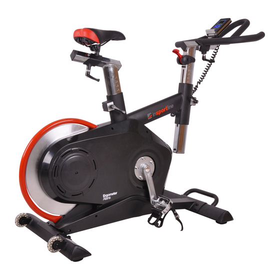
- Page 1 USER MANUAL – EN IN 8727 Spinning Bike inSPORTline Atana...
-
Page 2: Table Of Contents
CONTENTS SAFETY INSTRUCTIONS ............................ 3 IMPORTANT NOTES ............................3 EXPLODED DRAWING ............................4 PARTS LIST ................................4 CHECK LIST ................................8 ASSEMBLY INSTRUCTIONS ..........................9 SM7224-64 INSTRUCTION MANUAL ......................15... -
Page 3: Safety Instructions
SAFETY INSTRUCTIONS To ensure the best safety of the exerciser, regularly check it on damages and worn parts. If you pass on this exerciser to another person or if you allow another person to use it, make sure that that person is familiar with the content and instructions in these instructions. -
Page 4: Exploded Drawing
The general rule is that exercisers and training devices are no toys. Therefore, they must only be used by properly informed or instructed persons. Stop your work-out immediately in case of dizziness, nausea, chest pain or any other physical symptoms. - Page 5 Allen bolt M8x1.25x20L Spring washer D15.4xD8.2x2T Flat washer D16xD8.5x1.2T Front post Seat post Seat Seat adjustable tube L knob 25L Handlebar Computer fixing plate D plug Cover of front post Protective cover Inner insert Stop plate(1) Spring Stop plate(2) L knob 50L Left chain cover Right chain cover Left crank...
- Page 6 Inner flywheel Cable plug Swing connection fixing bracket Protecting ring Allen screw M6*1*15L,8.8级 Tension cable Lower tension cable Magnet fixing bracket Magnet Magnet fixing plate Axle of magnet fixing bracket Spring D1.2*55L Flat washer D18*D8.5*1.0T Nylon nut M8*1.25*8T Magnet cell Cross bolt M5*0.8*10L Adjustable round wheel Allen bolt M8*1.25*40L...
- Page 7 Square plug 38x38x18L Cross bolt M5*0.8*10L Computer Round-head screw M5*0.8*15L Nylon nut M6*1.0*6T Allen screw M6*1*15L Tension fixing plate Screw ST4.2*1.4*15L Fixing plate (1) Buffer D10*5.5T Hex bolt M5*0.8*10L, Flat washer D15*D5.2*1.0T Fixing plate (2) Round magnet Cross bolt M5*10L Sensor bracket Sensor cable Adaptor...
-
Page 8: Check List
CHECK LIST M8*1.25*20L D16*D8.5*1.2T D15.4*D8.2*2T M5*0.8*15L M5*10L... -
Page 9: Assembly Instructions
ASSEMBLY INSTRUCTIONS STEP 1 (x8) M8*1.25*20L (x8) D15.4*D8.2*2T (x8) D16*D8.5*1.2T Step-1 1) Assemble the front stabilizer (2) and rear stabilizer (3) onto the main frame (1) by using the flat washer (7), spring washer (6), and allen bolt (5). 2) Adjust the proper height by turning the adjustable round wheel (59). -
Page 10: Seat Post
STEP 2 DOWN DOWN Step-2 Handlebar post (8) and seat post (9) has been preassembled, you can adjust them stepless up and down by knob (22). - Page 11 STEP 3 (x1) M5*10L Step-3 1) Assemble the handlebar (13) onto the handlebar post (8) by knob (12) 2) Assemble the seat (10) onto the seat post (9) by knob (12), cross screw (97).
-
Page 12: Cable Plug
STEP 4 (x4) M5*1.0*10L (x2) M5*1.0*15L Step-4 1) Assemble the computer fixing plate (14) onto handlebar post (8) by using round-head screw (86) as the fig a shown. 2) Pass the upper computer cable (105) through the hole of computer fixing plate (14) as the fig b shown. 3) Insert the cable plug (41) as the fig c shown. -
Page 13: Adaptor
STEP 5 Step-5 1) Assemble the left pedal (25L) onto left crank by anti-clockwise, and assemble the right pedal (25R) onto right crank by clockwise. 2) Plug the adaptor (100) and turn on the computer. - Page 14 STEP 6 You can move the machine easily like the fig.
-
Page 15: Sm7224-64 Instruction Manual
SM7224-64 INSTRUCTION MANUAL DISPLAY FUNCTIONS ITEM DESCRIPTION TIME Setting range 0:00~99:00; Display range 0:00 ~ 99:59 SPEED Display range 0.0 ~ 99.9 DISTANCE Setting range 0.00~99.90KM; Display range 0.0 ~ 99.99 CALORIES Setting range 0~9990; Display range 0 ~ 9999 PULSE Setting range 0-30~230;... - Page 16 Mode Confirm/Enter setting or selection. OPERATION PROCEDURE POWER ON When POWER ON, buzzer will sound 1s and LCD full display for 2 seconds (Picture1). Then display wheel diameter and unit (Picture2). Then go to Standby mode (Picture 3). Picture 1 Picture 2 Picture 3 WORKOUT MODE SELECTION...
- Page 17 PROGRAM MODE Entering PROGRAM mode, LCD display as Picture 7. User can press UP or DOWN key to select program with 12 profiles from P1 to P12. After selecting the program, PX (X=1, 2, 3..12) will display in 2s. Press START/STOP to start workout.
- Page 18 TARGET H.R.C. MODE Before exercise in Target H.R.C. mode, user can press UP or DOWN to set up AGE (Picture 9) and confirm by MODE key. Then press UP or DOWN to select H.R.C: 55%, 75%, 90% or TAG, system will calculate pulse value accordingly and display on PULSE window (Picture 10).
- Page 19 +420 556 770 190, Mobile: +420 604 853 019, servis@insportline.cz Fax: +420 556 770 192, (Service +420 556 770 191) Web: www.insportline.cz, www.worker.cz, www.worker-moto.cz INSPORTLINE, s.r.o. Bratislavska 36, 911 05 Trencin, Slovakia CRN: 36311723, VAT ID: SK2020177082 Orders: +421(0)326 526 701, +421(0)917 649 192, objednavky@insportline.sk...
Need help?
Do you have a question about the IN 8727 Atana and is the answer not in the manual?
Questions and answers