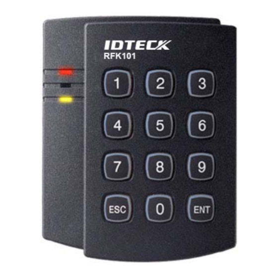
IDTECK RFK101 Quick Installation Manual
Pin & proximity card reader
Hide thumbs
Also See for RFK101:
- User manual (23 pages) ,
- Instruction (14 pages) ,
- User manual (19 pages)
Advertisement
Advertisement
Table of Contents

Related Manuals for IDTECK RFK101


Summary of Contents for IDTECK RFK101
- Page 1 Quick Installation Guide PIN & Proximity Card Reader...
- Page 2 Quick Installation Guide Table of Contents 1. Identifying Supplied Parts..................... 2 2. Installation ..........................3 3. Wire Color Table of the Reader .................... 4 4. Wire Connection to Access Controller .................. 5 5. Product Manual Download Information ................6...
- Page 3 Quick Installation Guide 1. Identifying Supplied Parts Please unpack and check the contents of the box. Main unit Wall Mount O-ring Quick Manual (1ea) (1ea) (5ea) (1copy) 3.5*40mm Screw 3.5*12mm Screw 6.0*30mm Anchor Bolt (4ea) (4ea) (4ea) 2 PIN Cable 6 PIN Cable 8 PIN Cable (1ea)
- Page 4 Quick Installation Guide 2. Installation 2-1. Using two 6-32 or M3 screws, install wall mount to the wall. 2-2. Insert 5 O-rings to the wall mount as indicated, then route the cable of the main unit through the center hole and push the main unit to wall mount to lock the main unit and make sure that the main unit is locked with wall mount.
- Page 5 Quick Installation Guide 3. Wire Color Table of the Reader IO PINs Signal Wire Color 2PIN (J1) Main Power (+12V) DC +12V Power Ground Black 6PIN (J2) Wiegand Data 0 Out WIK_DATA0 Green Wiegand Data 1 Out WIK_DATA1 White Not Connect Not Connect Orange RS-232-TX...
- Page 6 (In case of using a relay, connect NO to the LED Control wire and COM to GND) If you want to control the buzzer, connect Blue wire of RFK101 / IPK101 to Buzzer Control In GND of controller.(In case of using a relay, connect the NO to the Blue wire and COM to GND) Connect to the COM port of the PC.
- Page 7 For Registered Users of our Homepage: Visit IDTECK’s homepage (www.idteck.com). Click the Sign in button at the top of the Homepage and log in using your registered ID and P/W.
- Page 8 The specifications contained in this manual are subject to change without notice at any time. 5F, Ace Techno Tower B/D, 468, Gangseo-Ro, Gangseo-Gu, Seoul, 07573, Korea Tel : +82-2-2659-0055 Fax : +82-2-2659-0086 E-mail : webmaster@idteck.com Jul. 2016 Copyright ©2016 IDTECK Co., Ltd.
Need help?
Do you have a question about the RFK101 and is the answer not in the manual?
Questions and answers