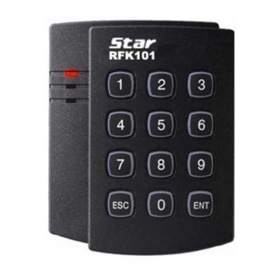
IDTECK Star RFK101 User Manual
Pin & proximity card reader
Hide thumbs
Also See for Star RFK101:
- User manual (19 pages) ,
- Instruction (14 pages) ,
- Quick installation manual (8 pages)
Table of Contents
Advertisement
Advertisement
Table of Contents

Related Manuals for IDTECK Star RFK101


Summary of Contents for IDTECK Star RFK101
-
Page 2: Table Of Contents
Table of Contents ............Table of Contents . - Page 3 ............ 17 2.2 Timing diagram ........... . 18 3 RS-232 output format ......... 18 3.1 Data format (Baud rate: 9600bps) ............ 18 3.2 Data structure ........19 11 FCC REGISTRATION INFORMATION .
-
Page 4: Safety Information
Safety Information CAUTION: TO REDUCE THE RISK OF ELECTRIC SHOCK, DO NOT REMOVE COVER (OR BACK) NO USER SERVICEABLE PARTS INSIDE. REFER SERVICING TO QUALIFIE D SERVICE PERSONNEL. This symbol indicates that dangerous voltage consisting a risk of electric shock is pres ent within this unit. - Page 5 3. Do not connect multiple controllers to a single adapter. Exceeding the capacity may cau se abnormal heat generation or fire. 4. Securely plug the power cord into the power receptacle. Insecure connection may caus e fire. 5. When installing the controller, fasten it securely and firmly. The fall of controller may ca use personal injury.
-
Page 6: Important Safety Instructions
IMPORTANT SAFETY INSTRUCTIONS 1. Read these instructions. 2. Keep these instructions. 3. Heed all warnings. 4. Follow all instructions. 5. Do not use this apparatus near water. 6. Clean only with dry cloth. 7. Do not block any ventilation openings. Install in accordance with the manufacturer’s ins tructions. -
Page 7: General
General The Star RFK101 / iPASS IPK101 is an elegant and attractive looking 10cm (4") read range pr oximity reader with a Keypad. The Star RFK101 / iPASS IPK101 has backlighting on the Key pad that ensures you successful operation even at night. The Star RFK101 / iPASS IPK101 all ows you to access the door with proximity card and PIN numbers. -
Page 8: Features
Features 125KHz Proximity & PIN Reader ● Star RFK101: PSK Modulation (IDTECK Format) iPASS IPK101: ASK[EM] Format Read Range: Up to 4 inches (10cm) ● User format available ● Output Format: ● Card: 26bit Wiegand and RS232 (default) ○ Keypad: 8bit burst (default), 26bit Wiegand (selectable) or 4bit burst (selectable) ○... -
Page 9: Identifying Supplied Parts
Identifying Supplied Parts Please unpack and check the contents of the box. -
Page 10: Specification
Specification Model RFK101 / IPK101 IDC80 / IDC170: Up to 4 inches (10cm) Read Range RFK101 IPC80 / IPC170: Up to 4 inch (10cm) IPK101 30ms Reading Time (Card) DC12V / Max.150mA Power / Current 3 Ports for External LED Control, Input Port 1 Port for External Buzzer Control Card: 26bit Wiegand and RS232 (default) -
Page 11: Installation
Installation 1. Use the provided Template on Page 18 to drill two 6-32 or M3 screw holes 3.3"(8.38c m) apart in vertical and one 1/2" hole at the center of these two holes. (If you have installed electric gang box then skip this step.) 2. -
Page 12: Wire Color Table Of The Reader
Wire Color Table of the Reader IO PINs Signal Wire Color 2PIN (J1) Main Power (+12V) DC +12V Power Ground Black 6PIN (J2) Wiegand Data 0 Out WIK_DATA0 Green Wiegand Data 1 Out WIK_DATA1 White Not Connect Not Connect Orange RS-232-TX TX OUT Purple... -
Page 13: Wire Connection To Access Controller
Wire Connection to Access Controller Connection Parts Connection Method Connect DC+12V wire of Power to Red wire of RFK101 / IPK101. Main Power (+12V) Connect GND wire of Power to Black wire of RFK101 / IPK101. Connect Green wire of RFK101 / IPK101 to Wiegand D0 input port of the Wiegand Data Out Controller. - Page 14 Connection Parts Connection Method f controller. (In case of using a relay, connect NO to the LED Control wire a nd COM to GND) If you want to control the buzzer, connect Blue wire of RFK101 / IPK101 to Buzzer Control In GND of controller.(In case of using a relay, connect the NO to the Blue wir e and COM to GND) Connect to the COM port of the PC.
-
Page 15: Operation
Operation Output Format Setting You can set output format of numeric input using output format setting switches. Select one between 4/8 bit Burst and 26bit Weigand format depending on the controller typ e receiving control input. Output format setting switches are on the back of RFK101 / IPK10 1 unit. -
Page 16: Output Mode Setting
Output Mode Setting Table 1. Jumpers Setting SW1#1 SW1#2 Card Output Format Keypad Output Format 26bit Wiegand + RS232 8bit Burst 26bit Wiegand + RS232 26bit Wiegand + RS232 26bit Wiegand + RS232 26bit Wiegand + RS232 26bit Wiegand + RS232 4bit Burst The default settings for SW1#1 and SW1#2 are “ON”(short circuit). -
Page 17: Advanced Operation (Optional)
If you enter a 1-8 digit PIN, ① 1234ENT Wiegand 00001234 RS232 00001234 ② 12345678ENT Wiegand 12345678 RS232 12345678 4. Burst + RS232 Output Format I. When you set output to Burst + RS232 format and press numeric keys on the keyp ad, you can hear a beep sound and the green LED turns on indicating PIN entry sta II. - Page 18 1. Supervisory Signal: This unit sends supervisory signal through reader’s output for a preset time. p.15 Operation...
-
Page 19: Output Format
Output Format 26bit Wiegand output format Data format Bit 1 : Even parity of bit 2 - bit 13 Bit 2 – 9 : Facility code (000 - 255) Bit 10 – 25 : ID number (00000 - 65,535) Bit 26 : Odd parity of bit 14 - bit 25 Timing diagram p.16... -
Page 20: 4 / 8Bit Burst Output Format (For Pin)
4 / 8bit Burst output format (for PIN) Data format (4bit Burst output format) Keypads Binary Hexa Keypads Binary Hexa 0000 0110 0001 0111 0010 1000 0011 1001 0100 1010 0101 1011 (8bit Burst output format) Keypads Binary Hexa Keypads Binary Hexa 11110000... -
Page 21: Rs-232 Output Format
RS-232 output format Data format (Baud rate: 9600bps) Data structure RS-232 output format p.18... -
Page 22: Fcc Registration Information
FCC REGISTRATION INFORMATION FCC Requirements Part 15 Caution: Any changes or modifications in construction of this device which are not expressly approved by the responsible for compliance could void the user's authority to operate the e quipment. NOTE: This device complies with Part 15 of the FCC rules. Operation is subject to the following two conditions;... -
Page 23: Rma Request
RMA Request If you have any questions or problems regarding the RMA services, please contact us using t he contact information below. Friendly representatives at IDTECK are always standing by to provide the best after sales services. IDTECK Headquarter 5F, Ace Techno Tower B/D, 684-1, Deungchon-Dong,...
Need help?
Do you have a question about the Star RFK101 and is the answer not in the manual?
Questions and answers