Table of Contents
Advertisement
Advertisement
Table of Contents

Subscribe to Our Youtube Channel
Related Manuals for IDTECK ipass IP10


Summary of Contents for IDTECK ipass IP10
-
Page 2: Table Of Contents
Table of Contents ............Table of Contents . -
Page 3: Safety Information
Safety Information CAUTION: TO REDUCE THE RISK OF ELECTRIC SHOCK, DO NOT REMOVE COVER (OR BACK) NO USER SERVICEABLE PARTS INSIDE. REFER SERVICING TO QUALIFIE D SERVICE PERSONNEL. This symbol indicates that dangerous voltage consisting a risk of electric shock is pres ent within this unit. - Page 4 3. Do not connect multiple controllers to a single adapter. Exceeding the capacity may cau se abnormal heat generation or fire. 4. Securely plug the power cord into the power receptacle. Insecure connection may caus e fire. 5. When installing the controller, fasten it securely and firmly. The fall of controller may ca use personal injury.
-
Page 5: Important Safety Instructions
IMPORTANT SAFETY INSTRUCTIONS 1. Read these instructions. 2. Keep these instructions. 3. Heed all warnings. 4. Follow all instructions. 5. Do not use this apparatus near water. 6. Clean only with dry cloth. 7. Do not block any ventilation openings. Install in accordance with the manufacturer’s ins tructions. -
Page 6: General
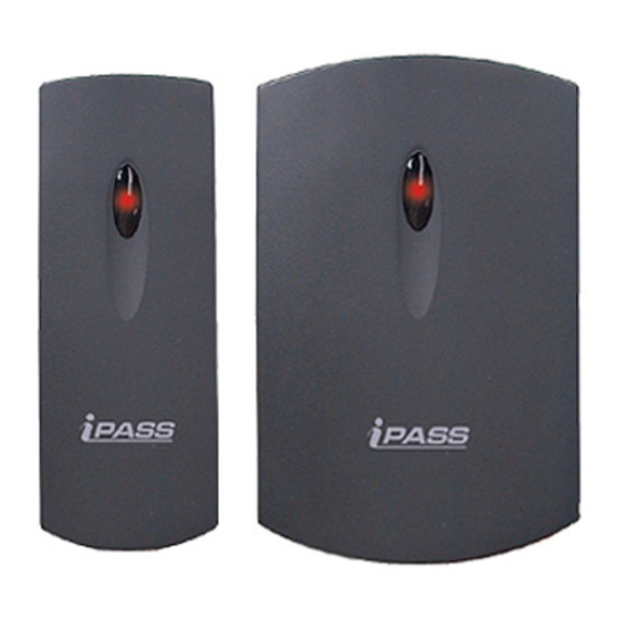
The iPASS IP10/20 is an elegant looking proximity reader. It can be easily mounted to metal door frame (mullion) or any flat wall surface. The iPASS IP10/20 is a credible product with e poxy potting that enables you to install it outside. -
Page 7: Features
Features 125KHz Proximity Card Reader ● ASK [EM] Format ● Read Range: Up to 4inch (10cm) ● User Format Available ● Output Format: 26bit Wiegand (Default), RS232 (Optional, Simultaneous output of 26b ● it Wiegand and RS232) Easy to Install on Metal Door Frame or Mullion (IP10) and Wall Mount (IP20) Suitable ●... -
Page 8: Identifying Supplied Parts
Identifying Supplied Parts Please unpack and check the contents of the box. -
Page 9: Specification
Specification Model IP10 IP20 IPK50: Up to 2 inches (5cm)IPC170 / IPC180: Up to 4 inches (10cm) Read Range 30ms Reading Time (Card) DC 12V / Max.150mA Power / Current 2 ports (External LED Control, External Buzzer Control) Input Port 26bit Wiegand (Default), RS232 (Optional) Output Format 2 Color LED (Red and Green) -
Page 10: Check Points And Tip
Check Points and Tip Recommended cable type and permissible length of cable ● Description Cable Specification Maximum Distance Reader (Power and Data) Belden #9512, 22 AWG 150m Reader -> ACU 4 conductor, shielded Belden #9514, 22 AWG 8 conductor, shielded * Need thicker wire if you connect the reader with high current consumption. - Page 11 wire will be reduced to 1/4 of single wire. Use separate power for the reader; Disconnect +12V wire from the ACU and conne ○ ct external power supply to the reader nearby then there will be no current flow thr ough the GND wire and no voltage drop between both ends of GND wire.
-
Page 12: Installation
Installation 1. Mullion/Wall Mount Drill two 6-32 or M3 holes 3.3"(8.38cm) apart in vertical and drill one 1/2" hole for the r eader cable 1.7"(4.31cm) apart from the top hole. (Skip this step, if you have installed an electric gang box.) 2. -
Page 13: Wire Color Table Of The Reader
Wire Color Table of the Reader p.11... -
Page 14: Wire Connection To Controller
Wire Connection to Controller p.12... -
Page 15: Operation
Operation 1. Once the power is applied, three beeping sounds can be heard and the LED toggles the color to red-green-red indicating that the reader is in standby mode after a successful in itialization and diagnostics 2. Present proximity card to the reader until you hear a beep sound. The LED is changing t he color to Green simultaneously and sends the RF card data to the controller. -
Page 16: Fcc Registration Information
FCC REGISTRATION INFORMATION FCC Requirements Part 15 Caution: Any changes or modifications in construction of this device which are not expressly approved by the responsible for compliance could void the user's authority to operate the e quipment. NOTE: This device complies with Part 15 of the FCC rules. Operation is subject to the following two conditions;... -
Page 17: Rma Request
RMA Request If you have any questions or problems regarding the RMA services, please contact us using t he contact information below. Friendly representatives at IDTECK are always standing by to provide the best after sales services. IDTECK Headquarter 5F, Ace Techno Tower B/D, 684-1, Deungchon-Dong,...
Need help?
Do you have a question about the ipass IP10 and is the answer not in the manual?
Questions and answers