Table of Contents
Advertisement
Quick Links
Advertisement
Table of Contents

Related Manuals for IDTECK RF900I-8


Summary of Contents for IDTECK RF900I-8
- Page 1 User Manual RF900I-8 User Manual...
-
Page 2: Table Of Contents
User Manual Catalogue 1.RF900I-8 VIEW ..............................3 1.1 F ..............................3 RONT 1.2 B ................................3 2. RF900I-8 CONFIGURATIONS ........................4 2.1 I ................................4 NITIAL 2.1.1 S 1: P ........................4 OWERING THE READER 2.1.2 S 2: C ....................4 ONNECTING NTENNA TO READER 2.1.3 S 3: C ....................4... -
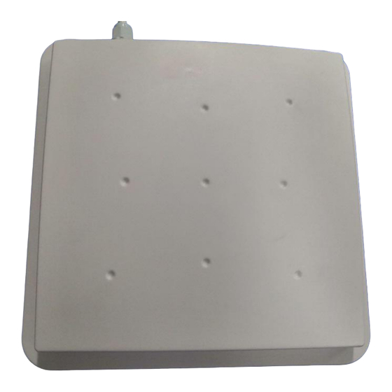
Page 3: 1.Rf900I-8 View
User Manual 1.RF900I-8 View 1.1 Front View 1.2 Back View... -
Page 4: 2. Rf900I-8 Configurations
User Manual 2. RF900I-8 Configurations 2.1 Initial Use 2.1.1 Step 1: Powering the reader Plug the power cable in, with the indicator light on and sound of a short beep, reader is ready. 2.1.2 Step 2: Connecting Antenna(s) to reader Connect the antenna(s) with the antenna port: 2.1.3 Step 3: Connecting Data Line to Reader... - Page 5 User Manual If the reader is connected via RS232, please select "RS232" in the connection mode, select the corresponding serial port number, and select the corresponding baud rate. The default baud rate is 115200. As shown below: Then click the "Connect " button, if the serial port is not occupied, the following information will be displayed in the Operation History below: If the reader is connected via TCP/IP , you need to perform the following steps: 1.
- Page 6 User Manual Subnet mask: 255.255.255.0 Port number: 4001 specific TCP/IP configuration, please refer accompanying document: \TCP-IP configuration\USR-TCP232-ED2 network module detailed instructions-20190624. When using the reader for the first time, please select the configuration shown in the figure below in the connection mode: Click the "Connect "button, if the connection is successful, the following information will be displayed in the Operation History blow:...
-
Page 7: Setting Rf Parameter
User Manual At this point, the connection between the reader and the computer has been successfully completed. Setting RF Parameter After successfully connecting the reader with PC, we need to set some of the most basic RF parameters, such as RF output power and RF spectrum. -
Page 8: Setting Rf Spectrum
User Manual The power range is 0dBm-33dBm, in increments of 1dB. The default value is 33dBm (2W). After this value is set, it will be automatically saved in the reader and will not be lost after the reader is powered off. The default RF output power is 33dBm. -
Page 9: Antenna Connection Detector
User Manual limited range. The default RF spectrum norm is FCC (902MHz-928MHz). Method 2: Set the RF spectrum manually. The user customizes the spectrum through three parameters: the starting frequency (unit is KHz, such as 860MHz, you need to enter 860,000), the interval between frequencies (the unit is KHz, the maximum frequency interval is 2500KHz, if you enter 2.5MHz, you need to enter 2500), the number of frequency points (Select the number of frequency points according to the input start frequency and frequency interval. -
Page 10: Measure Rf Port Return Loss
User Manual 2.2.4 Measure RF Port Return Loss Measure the return loss of the antenna port on the interface as shown in the figure below: Before measuring, you need to set the current working antenna port. The default antenna working port is 1. When measuring the return loss of other antenna ports, you need to set the corresponding working antenna. - Page 11 User Manual parameter (carrier frequency when the tag is read) also change in real time. But it will generate a lot of data. The reader adopts a dual-CPU architecture. Two different chips are responsible for reading tags and transmitting tag data. Reading tags and transmitting tag data are parallel, without interfering with each other, and not occupying each other's time, so users do not need to worry Data transmission will reduce the read performance of multiple tags.
- Page 12 User Manual The meaning of the data display is as follows: Inventoried Quantity Total number of inventory tags since click on Inventory Tag. Speed Speed of identification Tag, unit: piece / sec Total Tag Communication Total return EPC data of tags (Including repeated data) Command Duration Time of each Inventory Command takes, unit: ms Total Inventory Duration...
-
Page 13: Users Define Session Id & Inventorying Parameter Of Inventoried Flag
User Manual 2.3.2 Users define Session ID & Inventorying Parameter of Inventoried Flag According to the user-defined Session ID and Inventoried Flag parameters to inventory, the reader can inventory according to the user-defined session parameters (four types of session S0, S1, S2, S3) and the inventoried flag (two inventoried flags A, B) parameters . -
Page 14: Fast Switching Antenna To Inventory Tags
User Manual 2.3.3 Fast Switching Antenna to Inventory Tags In the operation of standard inventory tags (real time mode, each antenna needs to be commanded to set the corresponding working antenna before inventory), a single antenna inventory requires at least 200 milliseconds. Only after the inventory is completed, the reader can respond to new commands. -
Page 15: Accessing Iso-18000-6C Tag
User Manual The working time of each antenna can be set independently. The number of round 1 means that the working time of the antenna is 50ms, and the number of round*50ms is the working time of the antenna. Set the appropriate number of round according to the number of tags in front of the antenna. -
Page 16: Ead Tags
User Manual The following will introduce how to access tags one by one. 2.4.1Read tags The parameters for reading tags are entered in the interface shown in the figure below: Three parameters need to be input to read tags: select the tag storage area to be read, start address and data length. Note: The units of the start address and data length here are both WORD, which is a double byte of 16 bits. -
Page 17: Write Tags
User Manual Data length input 6 (unit word, read 12 bytes). (5) Click "Read " to read the contents of the corresponding storage area of the tag and display it in the data column of the list box. As many tags are manipulated, how many pieces of data will be displayed in the list. 2.4.2 Write tags The interface of the tag writing operation and the reading operation are in the same area. - Page 18 User Manual (3) Enter the access password, the default is 00 00 00 00. (4) Enter the starting address and data length. The upper four bytes of the EPC storage area are two bytes of CRC and two bytes of PC, so the starting address of the EPC number is 02 (unit word, Start reading after the upper four bytes). Data length input 6 (unit word, write 12 bytes).
-
Page 19: Lock Tags
User Manual Note that the maximum write length at one time is 32 Words (64 bytes, 512bits). 2.4.3 Lock Tags The operation interface of the lock tag is shown in the figure below: The lock tag must provide an access password to proceed. After the operation is successful, the following information will be returned: Similarly, how many tags are operated, how many pieces of data will be displayed in the list. -
Page 20: Kill Tags
User Manual 2.4.4 Kill Tags The operation interface of the kill tag is shown in the figure below: The killing tag must provide an kill password, and the kill password cannot be 00 00 00 00. Therefore, to kill a tag, you must first modify the content of the kill password in the password area through the write tag command. -
Page 21: Error Display Might Be Returned
User Manual After the selection is completed, click the "Select" button, and the following figure will be shown after successful operation: We see that the " Selected Tag" checkbox on the left has been ticked, and the selected EPC number appears in the text box on the left. -
Page 22: Other Settings 2.5.1Operating Temperature Monitoring
User Manual The above prompt will appear if there are no tags available for operation in the radio frequency area. For the meaning of other returned information, users can refer to the document: R2000 module serial interface communication protocol V4.0. Every time the UID of the tag is successfully read, the buzzer will beep once. -
Page 23: Setting Buzzer Status
User Manual The operation interface is shown in the below: Users can read and write GPIO through serial commands in their own applications. 2.5.3 Setting Buzzer Status The buzzer provides users with sound information about the status of the reader. The user can turn off the buzzer, or set it to sound once every time the tag is inventoried. -
Page 24: Develop Your Own Rfid Application
User Manual After the setting is successful, the new baud rate will be saved in the FLASH inside the reader, and will not be lost after the reader power off, restart the reader to make the setting effective. At this time, it must communicate with the reader at the new baud rate. - Page 25 User Manual The purple-blue information is the data sent by the PC to the reader, and the red information is the data returned by the reader to the PC. The function of manually sending data can be used by users to debug serial commands, and it has the function of automatically calculating the checksum.
- Page 26 User Manual FCC Warning This device complies with part 15 of the FCC rules. Operation is subject to the following two conditions: (1) this device may not cause harmful interference, and (2) this device must accept any inte rference received, including interference that may cause undesired operation.