Advertisement
Quick Links
Advertisement

Related Manuals for TVLogic LVM-071W


Summary of Contents for TVLogic LVM-071W
- Page 1 Multi User’s Manual Multi-Format LCD Monitors LVM Series LVM-071W...
-
Page 2: Table Of Contents
Contents LVM-071W Warnings ................... 2 Features .................... 3 Name & Function of Each Part ............5 Menu Contents ................. 9 Other Functions ................15 DVI Digital/Analog Input Signal Format .......... 19 Product Specification ..............21... -
Page 3: Warnings
Warning · Always use set voltage. - DC 12V · If liquid is spilled on or impacts this product, please disconnect the product immediately and seek professional help before continued use. · Keep unit disconnected during extended periods of disuse. ·... -
Page 4: Features
Features Multi-Format LVM-071W Series unit has the following features: Compatible with varied SDI signals The product is compatible with varied SDI Signals - 480i,576i,720p,1035i,1080i,1080p,1080psf Compatible with varied analog signals The product is compatible with varied analog signals - Composite, S-Video, Component, RGB... - Page 5 Wide Variety of Markers & Safety Areas Center Marker, Safety Area Marker, Aspect Marker, Display Size(Scan) Pixel To Pixel Provides both full screen and unscaled native image. Wide Screen/LED Backlight 24Bit RGB Interface Panel DC Compatible The product is powered by normal 12V source. Remote control function Simple remote controllability with single cable connection, no additional modules required...
-
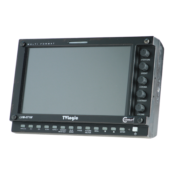
Page 6: Name & Function Of Each Part
Name & Function of Each Part <FRONT> TALLY APERTURE BRIGHT CHROMA CONTRAST VOLUME ANALOG POWER ENTER UNDERSCAN DOWN ASPECT MENU MARKER/HVDELAY WAVEFORM/VECTOR SCOPE BLUE ONLY/ MONO PHASE <REAR> DVI DIGITAL/ DVI ANALOG SDI-IN REMOTE SDI-OUT CVBS1/B/Pb FACTORY PGM CVBS2/G/Y/S-Y CVBS3/R/Pr/S-C DC IN AUDIO IN AUDIO OUT... - Page 7 <FRONT> · [ANALOG] button/lamp Used to select desired Analog Input. (CVB1/2/3, S-Video, Component, RGB) · [DVI] button/lamp Used to select desired DVI Input. (DVI DIGITAL, DVI ANALOG) · [SDI] button/lamp Used to select SDI Input. · [UNDERSCAN] button/lamp Used to transfer from OVER SCAN mode to UNDER SCAN mode. Mode changes in the order of UNDERSCAN ->...
- Page 8 · [MENU] button Used to activate the OSD menu. · [UP] button Used to navigate menu during OSD menu activation. It may also be used to toggle clockwise through 1:1 quadrants in native scan mode. · [DOWN] button Used to navigate menu during OSD menu activation. It may also be used to toggle counterclockwise through 1:1 quadrants in native scan mode.
- Page 9 <REAR> · REMOTE (RJ-45) Connection for remote control of monitor. · DVI DIGITAL/DVI ANALOG (DVI-I) Input connection for DVI-I. · SDI-IN (BNC) SDI signal input terminal. · SDI-OUT (BNC) SDI signal output terminal. · CVBS1/B/Pb (BNC) Signal input terminal used for COMPOSITE1, RGB B, COMPONENT Pb signals. ·...
-
Page 10: Menu Contents
Menu Contents Below is the description of each function of the menu. [1] PICTURE · Brightness This Item controls the degree of brightness. #Brightness can be adjusted by using the [BRIGHT] control knob on the front of the monitor. · Contrast This item controls the contrast ratio. - Page 11 · Aperture This item controls the picture sharpness. #Sharpness can be adjusted by using the [APERTURE] control knob on the front of the monitor. · NTSC Setup This item sets IRE value in NTSC mode between 0 IRE and 7.5 IRE. [2] PICTURE (DVI Analog Only) ·...
- Page 12 · Clocks/Line This item is adjust timing for signal sync · Auto Adjustment This item adjusts the input signal automatically. Phase, Clocks/Line and Image Position are also adjusted. [3] Color · Color Temp This item controls Color Temperature with presets of 3200K, 5600K, 6500K, 9300K, and User1, User2, User3 mode.
- Page 13 [4] Marker · Marker This selects the marker type when the MARKER is displayed on the screen. Compatible MARKER types are as follows: MODE MARKER CLASS 16:9, 4:3, 4:3 ON AIR, 15:9,14:9, SD 16:9 13:9, 1.85:1, 2.35:1, 1.85:1 & 4:3 SD 4:3 16:9 # MARKER may only be activated by pressing the MARKER button on the front of the...
- Page 14 · Marker Color This item controls Marker color. Selectable colors are white, gray, black, red, green, and blue. [5] Remote REMOTE (RJ-45) 1: Pin1 2: Pin2 3: Pin3 4: Pin4 5: Pin5 6: Pin6 7: Pin7 8: GND · Pin1 ~ Pin6 The user may connect RJ-45 jack to the remote terminal on the rear of the unit and designate a function for each pin.
- Page 15 [6] System · System Default User can use the System Default menu to initialize the values of the monitor excluding controlled values with the knobs On the front of the monitor. · Back Light This item controls the LED backlight setting. The value should be within range between MIN(0) and MAX(25).
-
Page 16: Other Functions
Other Functions 1) ANALOG INPUT Menu · LVM-071W Series unit is capable of processing varied ANALOG Input signals. · Press [ANALOG] button on the front of the monitor and activate the OSD menu as shown on the left. Select the input you desire by using the [UP]/[DOWN] button and press the [ENTER] button to confirm. - Page 17 CENTER After two seconds · LVM-071W monitor’s Pixel to Pixel mode displays input signal without scaling. · Press [UNDERSCAN] button on the front of the monitor to activate the[Pixel To Pixel] mode. · In the [Pixel To Pixel] mode, use the [UP]/[DOWN] buttons to toggle between 1:1 scan sections.
- Page 18 · Positions in HD Signal 1080i/1080p mode [UP] [UP] [DOWN] [DOWN] Center Left Top Mid Top [UP] [UP] [UP] [DOWN] [DOWN] [DOWN] Right Top Right Mid Right Bottom [UP] [UP] [UP] [DOWN] [DOWN] [DOWN] Mid Bottom Left Bottom Left Mid ·...
- Page 19 5) Waveform · Waveform Position Pixel To Pixel Waveform OFF Waveform ON #This function is only available with SDI Input. 6) Vector Scope · Vector Scope Position Vector Scope OFF Vector Scope ON #This function is only available with SDI Input.
-
Page 20: Dvi Digital/Analog Input Signal Format
DVI Digital/Analog Input Signal Format 1) DVI Analog Resolution DotClock Sync (Source) [MHz] (kHz) (Hz) (H/V) 640 x 350 70Hz (IBM) 25.175 31.469 70.086 640 x 480 60Hz (IBM) 25.175 31.469 59.940 720 x 400 70Hz (IBM) 28.322 31.469 70.087 640 x 480 67Hz (MAC) 30.240 35.000... - Page 21 2) DVI Digital Resolution DotClock Sync (Source) [MHz] (kHz) (Hz) (H/V) Pixel To Pixel 640 x 350 70Hz (IBM) 25.175 31.469 70.086 640 x 480 60Hz (IBM) 25.175 31.469 59.940 720 x 400 70Hz (IBM) 28.322 31.469 70.087 640 x 480 67Hz (MAC) 30.240 35.000 66.667...
- Page 23 LVM - 570W LHM - 400W LHM - 460W LHM - 570W Developed by For more information please visit : www.tvlogic.co.kr Suite 914 ACE TECHNO TOWER-9, 345-30 Gasan-Dong, GuemChun-Gu, Seoul, Korea TEL : +82-2-2026-1333 FAX : +82-2-2026-1339 E-mail : support@tvlogic.co.kr...
Need help?
Do you have a question about the LVM-071W and is the answer not in the manual?
Questions and answers