Table of Contents
Advertisement
Quick Links
Advertisement
Table of Contents

Related Manuals for TVLogic LVM-241S


Summary of Contents for TVLogic LVM-241S
- Page 1 Multi Format LCD Monitor LVM-171S LVM-241S...
-
Page 3: Table Of Contents
Contents 1. Caution 2. Main Features 3. Controls & Functions 4. Menu Tree & Adjustment 5. Menu Operations [1] PICTURE [2] VIDEO [3] COLOR [4] GPI [5] MARKER [6] FUNCTION KEY [7] WAVEFORM & FOCUS [8] AUDIO [9] SYSTEM 6. Button Functions 7. -
Page 4: Caution
AC outlet, and ● DC 12V (LVM-171S) request a qualified service person to perform ● DC 12V/24V (LVM-241S) repairs. ● a . When the power cord or plug in damaged. • All operating instructions must be read and b. - Page 5 1. Caution • When relocating the product placed on a cart, • When mounting the product be sure to install it must be moved with the utmost care. the product Sudden stops, excessive force and uneven according to the method recommended by floor surface can cause the product to fall from the manufacturer.
-
Page 6: Main Features
TVLogic or a TSL protocol. - Stereo Audio Out & External Audio In through phone Jack. Power ● - The LVM-171S and the LVM-241S are powered by normal AC source as well as DC 12V (LVM- 171S) / DC 12V/24V (LVM-241S). Additional Features ●... -
Page 7: Controls & Functions
3. Controls & Functions LVM-171S : FRONT POWER SOURCE SCAN ASPECT MARKER FUNCTION/ FUNCTION SELECT POWER SOURCE MENU/EXIT SCAN KNOB(UP/DOWN/ENTER) ASPECT MARKER USB(Firmware Update) AUDIO OUT FUNCTION/ FUNCTION SELECT MENU/EXIT KNOB(UP/DOWN/ENTER) USB(Firmware Update) AUDIO OUT LVM-171S: REAR REMOTE RS-422 IN RS-422 OUT CVBS1/Y/G/S-Y OUT CVBS1/Y/G/S-Y IN... - Page 8 ● ● - Tally lamp that can be toggled in green - These buttons are the shortcut keys in or red using the REMOTE(RJ-45) port or order to activate preassigned functions TVLogic’s management program(Observer). immediately. [POWER] [MENU/EXIT] ● ● - Used to turn the power on and off.
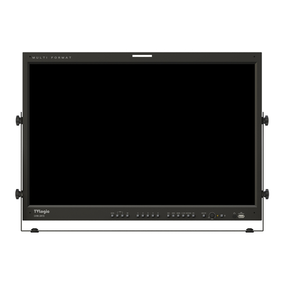
- Page 9 3. Controls & Functions LVM-241S : FRONT SCAN ASPECT MARKER B.LIGHT VIDEO RANGE SDI B SDI A INFO. SOURCE MENU/EXIT KNOB(UP/DOWN/ENTER) POWER SCAN ASPECT AUDIO OUT MARKER USB(Firmware Update) B.LIGHT VIDEO RANGE SDI B SDI A INFO. SOURCE MENU/EXIT KNOB(UP/DOWN/ENTER)
- Page 10 3. Controls & Functions LVM-241S : FRONT [PBP] Button/Lamp [SOURCE] ● ● - Used to select PBP(Picture-by-Picture) - Used to select the desired input source or function. used to select the PBP Mode. Use the Knob - Selects the order of operation: mode 1 ->...
- Page 11 3. Controls & Functions LVM-241S : FRONT [B. LIGHT] Button [FRONT TALLY] ● ● - Used to activate the Backlight menu. Use the - Tally lamp that can be toggled in green KNOB button to adjust the value. or red using the REMOTE(RJ-45) port or TVLogic’s management program(Observer).
- Page 12 - 100 ~ 240V AC 50/60Hz [RS422 IN & OUT] (RJ-45) ● - Used to control the monitor with protocol [POWER S/W] ● provided by TVLogic or to support TSL - Power On/Off Switch protocol. [DC IN] ● [CVBS1~3/YPbPr/S-Y B S-C IN & OUT] (BNC) - 12V DC (LVM-171S) ●...
-
Page 13: Menu Tree & Adjustment
4. Menu Tree & Adjustment [1] Menu Construction [3] Menu Control Sequence This Picture is the menu structure for Menu control sequence follows the order ● ● LVM-171S/241S. below : 1. Press the MENU button to activate the OSD menu. 2. - Page 14 4. Menu Tree & Adjustment [4] MENU TREE BRIGHTNESS GPI PIN 1~GPI PIN 8 CONTRAST GROUP ID PICTURE CHROMA MONITOR ID APERTURE DHCP EHS(DE-INT) MODE ID ADDRESS FAST MODE SUBNET MASK 3G FORMAT GATEWAY VIDEO RANGE SELECT VIDEO PORT NO. TIME CODE ENABLE SETTING APPLY BLUE ONLY...
- Page 15 4. Menu Tree & Adjustment [4] MENU TREE KEY LED LEVEL METER SELECT Function Key KEY MAPPING F1~F5 LEVEL METER DISPLAY WAVEFORM DISPLAY LEVEL METER REFERENCE WAVEFORM INTENSITY LEVEL METER DECAY TIME WAVEFORM TRANS LEVEL METER SIZE AUDIO WAVEFORM COLOR LEVEL METER POSITION LINE WAVEFORM VOLUME...
-
Page 16: Menu Operations
5. Menu Operations [1] PICTURE [2] VIDEO Picture LVM-171S BRIGHTNESS CONTRAST CHROMA APERTURE BRIGHT ● - Used to set the brightness level from -100 to 100. EHS(DE-INT) MODE • Brightness can be adjusted by using the ● - This item toggles the 4:4:4 video processing control knob on the front of the monitor. -
Page 17: Color
5. Menu Operations [3] COLOR Color Gamut ● - Used to select the standard color gamut. - Available options are BT.709, BT.2020, DCI-P3, SGamut3 and Native. - Activates only in the User1/2/3 mode. Color Temp. ● - Controls the color temperature and allows instant access to preset the color temperature settings. - Page 18 5. Menu Operations [3] COLOR COLOR COPY ● Color LVM-171S - Used to copy the R/G/B Gain value of pre- stored color temperature settings. COLOR Temp. 6500K - In User mode, find and select the color temperature to be used with the Knob and GAIN RED press the Knob button to copy and apply the GAIN GREEN...
-
Page 19: Gpi
5. Menu Operations [4] GPI Menu Classifi- Settable Values cation NONE, ANALOG CHANNEL, HDMI CHANNEL, SDI-A/B CHANNEL TALLY RED, TALLY GREEN, BLUE ONLY, ASPECT, H/V DELAY, 16:9 MARKER, 4:3 MARKER, 4:3 ON AIR MARKER, 15:9 MARKER, 14:9 MARKER, 13:9 MARKER, 1.85:1 MARKER, 2.35:1 MARKER, 1.85:1&4:3 MARKER,... - Page 20 Network. MONITOR ID ● - Used to set the ID of each monitor for the TVLogic control protocol or DYNAMIC UMD using RS-422/485 communication or Network. - Available values are between 0,2,4 ~ 98. - Right screen in PBP mode is automatically set to +1 of the monitor ID.
-
Page 21: Marker
5. Menu Operations [5] MARKER FIT MARKER ● - Used to activate or inactivate the Fit Marker function. - When the Marker type is selected in the Marker menu, a border line of the Safety Area will be displayed inside the Marker. Images below show the difference between Fit Marker ON and OFF. -
Page 22: Function Key
5. Menu Operations [6] FUNCTION KEY [7] WAVEFORM & FOCUS KEY LED ● - Used to control the Key Lamp on the front of the monitor. F1 / F2 / F3 KEY MAPPING ● - User can select the function for the F1 / F2 / F3 button. - Page 23 5. Menu Operations [7] WAVEFORM & FOCUS LUMA(Y’) ZONE CHECK ● - Displays the Luma(Y’) level of the input image in colors. - Can select between [Color Pattern] or [Zebra Pattern]. - Each pixel’s Y’ analyzed and changed to a certain color or zebra pattern according to the Index on the right side of the screen.
- Page 24 5. Menu Operations [7] WAVEFORM & FOCUS RANGE ERROR ● - Used to set whether or not to activate Y MAX, Y MIN, C MAX, C MIN, Y PICTURE BLINK and C PICTURE BLINK functions. - The values of Y MAX, Y MIN, C MAX, C MIN are indicated in WAVEFORM/VECTOR.
-
Page 25: Audio
5. Menu Operations [8] AUDIO LEVEL METER SIZE ● AUDIO LVM-171S - Used to control the size of the Audio Level Meters. LEVEL METER SELECT - Available modes are SMALL, SMALL TRANS, NORMAL, NORMAL TRANS, LARGE and LEVEL METER DISPLAY UD MODE(SDI-4CH) LARGE TRANS. -
Page 26: System
5. Menu Operations [9] SYSTEM LVM-171S System LOCK NUMBER * * * * LOCK ENABLE INTERNAL PATTERN SET DEFAULT S/W UPGRADE VERSION 00 . 00 . 00 . 00 INTERNAL PATTERN ● - Generates White Pattern internally. - Selectable range is from 0% to 100% with 5% increment. -
Page 27: Button Functions
6. Button Function [1] PBP(Picture-by-Picture) / PIP(Picture-in-Picture) PBP(PIP) Mode Select ● - Use the PBP button to change into PBP Screen. Available modes are as shown below. • In order to avoid confusion of terms, the PIP mode on the screen is collectively referred to as PBP. <PBP>... - Page 28 6. Button Function [2] USER Aspect Used to adjust the Width /Height display ● USER ASPECT ratio. 1. Press the [ASPECT] button on the front of WIDTH +1920 the monitor to acticate the [USER ASPECT] mode. HEIGHT +1080 2. After the activation, press the Knob to begin controlling.
- Page 29 6. Button Function [3] Waveform / Vectorscope Vector Scope Waveform Y ● ● - Displays the color components ‘B-Y’ and - Displays the Luma(Y’) component of the ‘R-Y’of the input signals onto the X-Y axis. input signal into waveform. - Two different types of Vetorscopes are disp layed according to SD or HD input signals.
- Page 30 6. Button Function [4] Line Select (Waveform / Vector Scope) Used to select specific Vertical Line for Waveform / Vector. ● - It is available when the Line Waveform is activated. - To activate this feature, go to [Waveform]- [Waveform/Vector]-[Line Waveform]-[Select Line Position] and use the Knob to select a vertical line.
- Page 31 6. Button Function [5] Luma(Y’) Zone Check Color Pattern Type. Zebra Pattern Type. ● ● - Displays the Luma(Y’) level of the input - Displays the pixels with designated Luma(Y’) image in colors. levels with zebra pattern. - Y’ ≥ 100% : Pixels with higher Y’ level than - Y’...
- Page 32 6. Button Function [6] Focus Assist [7] Range Error Focus Assist function assigns a color to Pixels with Y’ or C’ levels exceeding the ● ● the pixels on the boundaries of the image designated levels of Y MAX, Y MIN, C MAX to inform the user to achieve the best and C MIN shall blink.
-
Page 33: Video Support Resolution
7. Video Support Resolution [1] SDI Mode Input Signal Signal Foramt (SD SDI) Interfaces 720x487 SD SDI (59.94i) YCbCr 4:2:2 10bit single link 720x576 (50i) Input Signal Signal Format (3G SDI) Interfaces 1920x1080 (60p/59.94p/50p) YCbCr 4:2:2 10bit 3G-SDI (A/B) single link 1920x1080 (30/29.97/25/24/23.98/ RGB 4:4:4 10bit / 12bit 30sF/29.97sF/25sF/24sF/23.98sF) - Page 34 7. Video Support Resolution [3] DVI-ANALOG Mode Resolution Frequency 640 X 480 60Hz, 75Hz 720 X 400 70Hz 800 X 600 60Hz, 72Hz, 75Hz 1024 X 768 60Hz, 70Hz, 75Hz 1366 X 768 60Hz / 75Hz [4] DVI-DGITAL GRAPHIC Mode Resolution Frequency 640 X 480...
-
Page 35: Product Specifications
8. Product Specifications LVM-171S Size 16.5” Resolution 1920 X 1080 (16:9) Pixel Pitch 0.1905(H) X 0.1905(V) mm Color Depth 1.07B Viewing Angle H: 178 degrees / V: 178 degrees Luminance of white 450 cd/ m (Center) Contrast Ratio 1400 : 1 Display Area 365.8(H) X 205.7(V) mm 1 X DVI-I... - Page 36 8. Product Specifications LVM-241S Size 24” Resolution 1920 x 1200 (16:10) Pixel Pitch 0.270(H) x 0.270(W) mm Color Depth 1.07B Viewing Angle H: 178 degrees / V: 178 degrees Luminance of white 400 cd/m (Center) Contrast Ratio 1,500 : 1 Display Area 518.4(H) x 324.0(V) mm...
-
Page 37: Optional Accessories
9. Optional Accessories Gold-Mount RACK MOUNT ANY DISPLAY UP TO 24” 8.4 inch 9 inc h 7 inch 15 inch 17 inch 21 inch 24 inch Multi Format LCD Monitor 37... -
Page 38: Multi Format Lcd Monitor
38 Multi Format LCD Monitor... - Page 40 FOR MORE INFORMATION PLEASE VISIT : http://www.tvlogic.tv 12F, ACE HIGH-END 8, 84 Gasan digital 1-ro, Geumcheon-gu, Seoul, 08590, KOREA 부사장 TEL : +82-70-8668-6611, FAX : 82-2-6123-3201, E-mail : sales@ t vlogic.co.kr 조 성 일 153-802 서울특별시 금천구 가산동 345-4 에이스하이엔드 8차 12층...
Need help?
Do you have a question about the LVM-241S and is the answer not in the manual?
Questions and answers