Table of Contents
Advertisement
Quick Links
Advertisement
Table of Contents

Subscribe to Our Youtube Channel
Related Manuals for TVLogic SRM-074W-N


Summary of Contents for TVLogic SRM-074W-N
- Page 1 Multi Format Broadcast LCD Monitor LVM-074W SRM-074W-N...
-
Page 3: Table Of Contents
Contents 1. Caution 2. Main Features 3. Controls & Functions 4. Menu Tree & Adjustment 5. Menu Operations [1] Picture [2] Color [3] Marker [4] GPI/UMD [5] Waveform [6] Audio [7] Display & Set 6. Button Functions 7. Other Functions 8. -
Page 4: Caution
1. Caution Always use set voltage. (DC 12V) • • If any of the following conditions occur, unplug When using a DC Adapter other than the the power cord from the DC outlet, and request • a qualified service person to perform repairs. one supplied by the manufacturer, please a. - Page 5 1. Caution • When mounting the product on a wall or ceiling, • Sudden stops, excessive force and uneven be sure to install the product according to the floor surface can cause the product to fall from method recommended by the manufacturer. the cart.
-
Page 6: Main Features
2. Main Features LVM-074W/SRM-074W-N Monitors contain the following features: • Compatible with various SDI signals • Knob Control - Easy to adjust user configuration using the formats (SD/HD/3G) control knob on the front of the monitor. - This product is compatible with various SDI signals - SD/HD/3G(A/B)-SDI 480i, 576i, 1080i, •... -
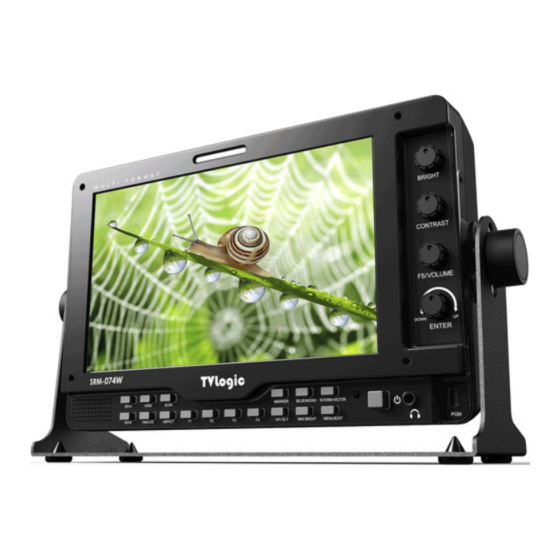
Page 7: Controls & Functions
3. Controls & Functions SDI-A HDMI SCAN MARKER BLUE/MONO W-FORM/VECTOR LVM-074W / SRM-074W-N : FRONT SDI-B ANALOG ASPECT H/V DLY. MAX BRIGHT MENU/EXIT SDI-A HDMI SCAN MARKER BLUE/MONO W-FORM/VECTOR SDI-B ANALOG ASPECT H/V DLY. MAX BRIGHT MENU/EXIT LVM-074W / SRM-074W-N : REAR... - Page 8 3. Controls & Functions FRONT • [SDI-A] Button/Lamp • [H/V DELAY] Button/Lamp - Used to select SDI-A input. - Used to check horizontal sync and vertical sync simultaneously by moving the display to the left, right, up and down. • [SDI-B] Button/Lamp - In this mode, the brightness of image - Used to select SDI-B input.
- Page 9 • PGM (Mini USB) • [UP/DOWN/ENTER] Knob - This terminal is used to upgrade the firmware or color calibration made by TVLogic. - Used to move within the menu when OSD menu is activated, and is also used to decrease or increase the value of the selected •...
- Page 10 - Tally lamp that can be toggled in green or red - Used to control the monitor with protocol using the REMOTE(RJ-45) port. provided by TVLogic or to support TSL protocol. • [SDI-IN A] (BNC) - HD/SD SDI signal input terminal for SDI A.
-
Page 11: Menu Tree & Adjustment
2. Move to a desired menu by rotating the Knob. • This Picture is the menu structure for 3. Press the Knob to select a menu and move to LVM-074W(SRM-074W-N) select a sub-menu by rotating the Knob. 4. Press the Knob to select the desired sub menu. -
Page 12: Menu Operations
5. Menu Operations [1] Picture [2] Color • Brightness • Color Temp. - Used to set the brightness(=offset) level from - Controls color temperature and allows instant -100 to 100. access to preset color temperature settings. # Press the Knob to adjust Brightness quickly. - Available color temperatures are 3200K, 5600K, 6500K, 9300K and User 1/2/3. -
Page 13: Marker
5. Menu Operations [3] Marker • Marker • Marker Mat - Used to activate the Marker function. - Used to set the darkeness level outside of the - Available marker types are OFF, 16:9, 4:3, 4:3 MARKER area from OFF(transparent) to 7(Black). ON AIR, 15:9, 14:9, 13:9, 1.85:1, 2.35:1, 1.85:1 &... -
Page 14: Gpi/Umd
5. Menu Operations [4] GPI / UMD - The selectable values are as follows : Menu Classifi- Settable Values cation NONE, Analog Channel, HDMI Channel, SDI-A Channel, SDI-B Channel, TALLY R, TALLY G, TALLY Y, UNDER SCAN, 1:1 SCAN, ASPECT, H/V DELAY, BLUE ONLY, 16:9 MARKER, 4:3 MARKER, 4:3 ON AIR MARKER, 15:9 MARKER, •... - Page 15 5. Menu Operations [4] GPI / UMD • XLR TALLY On/Off Used to set Tally operation according to the input level of TALLY IN terminal which is among the terminals of XLR 4P connector in the rear. • XLR TALLY Operating Level - Used to set the input level of Tally operation.
-
Page 16: Waveform
5. Menu Operations [5] Waveform • Select Line Position - Used to select specific Vertical Line for Waveform/Vectorscope. - It is available when LINE Waveform is activated. - To activate this feature, go to [WFM/LevelCHK]- [Waveform/Vector]-[Select Line Position] and use the Knob to select a vertical line. - Control range varies according to the resolution of the input SDI signal. - Page 17 5. Menu Operations [5] Waveform C Min • - Used to set the minimum chroma(C’) level from 0 to 255. - Pixels with values exceeding the min C’ level will blink in the screen, and displayed as red on the Waveform. Y Picture Blink •...
-
Page 18: Audio
5. Menu Operations [6] Audio • Level Meter Reference - Display the default audio level meter value, Available options are -18dB and -20dB. - Audio level meter within selected value turns to green and exceeded audio level is displayed in yellow. - Audio level exceeding -4dB is displayed in red. -
Page 19: Display & Set
5. Menu Operations [7] Display & Set • System Default • Firmware Version - Used to initialize OSD values to factory default. - Displays current firmware version. • Zoom • Back Light - Used to magnify the image up to 90% on a - Used to indicate the backlight level. - Page 20 5. Menu Operations [7] Display & Set • Focus Assist Color - Used to select a color for FOCUS ASSIST among red, green and blue. • Focus Assist Level - Used to set the edge difference value between the edges in an image. - Available values are from 0 to 100.
-
Page 21: Button Functions
[2] SDI Button * This product is capable of processing all * LVM-074W unit is capable of (SRM-074W-N) input signals usable in ANALOG mode. processing dual SDI Input signal. 1. Press [SDI] button on the front of the * The Analog input settings are as follows: monitor and activate the OSD menu as shown on the below. - Page 22 6. Button Functions [4] Function Key Set Button [5] SCAN Button • This product supports various scan modes. • Used to make a quick setting of the • Press [SCAN] button on the front of the Function Key. monitor to activate different scan modes. 1.
-
Page 23: Other Functions
7. Other Functions [1] Pixel to Pixel * LVM-074W(SRM-074W-N) monitor provide pixel count info using Pixel to Pixel mode. * Select [Scan] mode in the OSD menu to activate the[Pixel To Pixel] mode. * After activation of [Pixel To Pixel] mode, use the Knob to move the position. - Page 24 7. Other Functions [2] User Aspect • Select [Aspect] mode in the OSD menu to activate the[User Aspect] mode. • After activation, press the Knob to get ready for controlling. • # To adjust the 16:9 aspect ratio of 1920X1080 Adjust the ratio using the Knob.
- Page 25 7. Other Functions [3] Waveform / Vectorscope • Waveform Y • VectorScope - Displays the Luma(Y’) component of the input - Displays the color components ‘B-Y’ and ‘R-Y’ signal into waveform. of the input signals onto the X-Y axis. - Two different types of Vetorscopes are displayed according to SD or HD input signals.
- Page 26 7. Other Functions [4] Line Select (Waveform/VectorScope) [5] Zoom • Used to select specific Vertical Line for • Used to magnify the input signal from 0% to WaveForm/VectorScope. 90%. • It is available when LINE WaveForm is activated. • Supports Zoom Width Scroll / Zoom Height Scroll function.
- Page 27 7. Other Functions [6] Luma(Y’) Zone Check Color Pattern Type Zebra Pattern Type ■ ■ • Displays the pixels with designated Luma(Y’) • Displays the Luma(Y’) level of the input image levels with zebra pattern. in colors. • Y’ ≥ 100%: Pixels with Y’ level over 100% turn to •...
- Page 28 7. Other Functions [7] Focus Assist [8] Range Error • • Pixels with Y’ or C’ levels exceeding the Focus Assist function assigns a color to the designated levels of Y MAX, Y MIN, C MAX and C pixels in the shape or boundary area of the MIN shall blink.
- Page 29 If the circle is compared in Live/Rec Full mode, the output of the circle is deformed. 2. Both LVM-074W(SRM-074W-N) connected DSLR and LVM-074W(SRM-074W-N) connected HDMI to SDI Conversion should be compared to cirlce in Zeroscan mode. It is deformed if user selects in Overscan and Underscan mode.
- Page 30 7. Other Functions [10] HDMI To SDI Conversion-Out [12] Internal Pattern • Video source from ‘HDMI input’ terminal can be • Displays internally generated test patterns. output through ‘SDI throughout’ terminal. • The pattern consists of ColorBar and Pluge+ Grayscale Patterns. Full screen colors of various Note: HDSLR camera manufacturers usually gray levels(0~100%) are also embedded.
- Page 31 8. Product Specifications LVM-074W Size 7” Resolution 1024 X 600 (16:9) Pixel Pitch 0.15(H) X 0.15(W) mm Color Depth 16.7M (True 8bit) Viewing Angle H : 170 degrees / V : 170 degrees Luminance of white 400 cd/ m (Center) Contrast Ratio 800 : 1 Display Area...
-
Page 32: Optional Accessories
8. Product Specifications SRM-074W-N Size 7” Resolution 1024 X 600 (16:9) Pixel Pitch 50(H)μm × 150(V) μm Color Depth 16.7M Colors (Dithered 8bits) Viewing Angle H : 160 degrees / V : 160 degrees Luminance of white (Max.) 1,500 cd/ m (Typ. - Page 33 9. Optional Accessories Sun-Hood External Acrylic Protector V-Mount Gold-Mount Tripod Ball Head Carrying Bag with Hood (Rain Cover) External Tally Rack Mountable Kit Multi Format LCD Monitor 33...
- Page 34 MEMO 34 Multi Format LCD Monitor...
- Page 36 FOR MORE INFORMATION PLEASE VISIT : http://www.tvlogic.tv 12F, ACE HIGH-END 8, 84, Gasan digital 1-ro, Geumcheon-gu, Seoul, 153-797, KOREA 부사장 TEL : +82-70-8668-6611, FAX : 82-2-6123-3201, E-mail : sales@ t vlogic.co.kr 조 성 일 153-802 서울특별시 금천구 가산동 345-4 에이스하이엔드 8차 12층...
Need help?
Do you have a question about the SRM-074W-N and is the answer not in the manual?
Questions and answers