
Related Manuals for Kramer VM-114H4C


Summary of Contents for Kramer VM-114H4C
-
Page 1: User Manual
K R A ME R E LE CT R O N IC S L TD . USER MANUAL MODEL: VM-114H4C 2 Input 1:4 HDMI DA/4x CAT5 Outputs P/N: 2900-000645 Rev 9... -
Page 3: Table Of Contents
Figures Figure 1: VM-114H4C Front Panel Figure 2: VM-114H4C Rear Panel Figure 3: Connecting the VM-114H4C 2 Input 1:4 HDMI DA/4x CAT5 Outputs Figure 4: VM-114H4C RS-232 Control and Pass-through Figure 5: VM-114H4C IR Control and Pass-through Example One Figure 6: VM-114H4C IR Control and Pass-through Example Two... -
Page 4: Introduction
Room Connectivity; GROUP 10: Accessories and Rack Adapters; GROUP 11: Sierra Video Products; GROUP 12: Digital Signage; GROUP 13: Audio; and GROUP 14: Collaboration. Congratulations on purchasing your Kramer VM-114H4C 2 Input 1:4 HDMI DA/4x CAT5 Outputs, which is ideal for the following typical applications: ... -
Page 5: Getting Started
Achieving the Best Performance To achieve the best performance: Use only good quality connection cables (we recommend Kramer high- performance, high-resolution cables) to avoid interference, deterioration in signal quality due to poor matching, and elevated noise levels (often associated with low quality cables) ... -
Page 6: Safety Instructions
Kramer Electronics has made arrangements with the European Advanced Recycling Network (EARN) and will cover any costs of treatment, recycling and recovery of waste Kramer Electronics branded equipment on arrival at the EARN facility. For details of Kramer’s recycling arrangements in your particular country go to our recycling pages at http://www.kramerelectronics.com/support/recycling/. -
Page 7: Overview
Overview The high quality VM-114H4C is a switcher/distribution amplifier for HDMI and TP (Twisted Pair) signals. It reclocks and equalizes one of two selectable input signals and distributes it to four TP outputs. In particular, the VM-114H4C: Supports up to 4.95Gbps (1.65Gbps bandwidth per graphic channel) (DGKat) ... -
Page 8: Using Twisted Pair Cable
Using Twisted Pair Cable Kramer engineers have developed special twisted pair cables to best match our digital twisted pair products; the Kramer: BC-DGKat524 (CAT 5 24 AWG), the Kramer: BC-DGKat623 (CAT 6 23 AWG cable), and the Kramer: BC-DGKat7a23 (CAT 7a 23 AWG cable). -
Page 9: Defining The Vm-114H4C
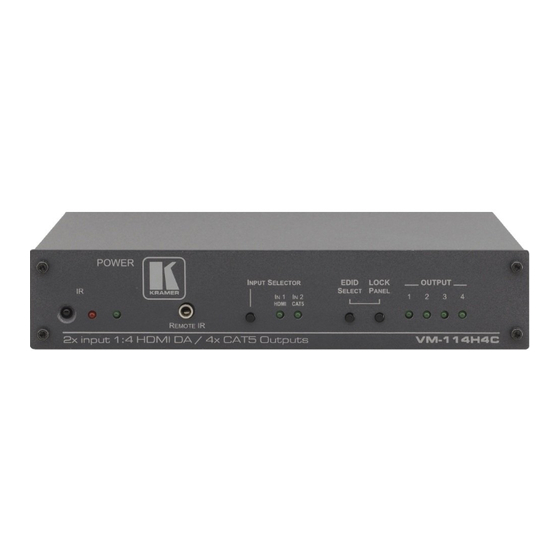
Defining the VM-114H4C This section defines the VM-114H4C. Figure 1: VM-114H4C Front Panel Feature Function IR Remote Control Sensor Sensor for the remote control IR transmitter IR LED Lights yellow when receiving signals from the IR remote control transmitter REMOTE IR 3.5mm Mini... -
Page 10: Figure 2: Vm-114H4C Rear Panel
IN2 (CAT5) Input RJ-45 Connect to a TP source (for example, PT-571 HDMI Connector Line Transmitter, VM-114H2C or VM-114H4C) TP RJ-45 Output Connectors Connect to the TP acceptors (for example, PT-572+ (1-4) HDMI Line Receiver, VM-114H or VM-114H4C) VM-114H4C - Overview... -
Page 11: Connecting The Vm-114H4C
PT-572+ Line Receiver, the VM-114H or the VM-114H2C). 4. (Optional) Connect the front panel remote IR 3.5mm mini jack to the remote IR sensor. 5. (Optional) Connect a PC via RS-232 to the RS-232 port on the VM-114H4C (see Section 4.1). -
Page 12: Connecting To The Vm-114H4C Via Rs-232
Figure 3: Connecting the VM-114H4C 2 Input 1:4 HDMI DA/4x CAT5 Outputs Connecting to the VM-114H4C via RS-232 You can connect to the VM-114H4C via an RS-232 connection using, for example, a PC. Note that a null-modem adapter/connection is not required. -
Page 13: Using The Vm-114H4C
(Section 5.2) Acquiring the EDID Each input on the VM-114H4C has a factory default EDID loaded (see Section This lets you connect the power before having to connect one of the acceptors. The VM-114H4C reads the EDID, which is stored in the non-volatile memory. -
Page 14: Disabling/Enabling Deep Color Support
1. Disconnect the power. 2. Connect the output or outputs from which you want to acquire the EDID. 3. Connect the power while pressing the EDID SELECT button. 4. Perform steps 3 through 5 in Section 5.1. VM-114H4C - Using the VM-114H4C... -
Page 15: Rs-232, Ir Control And Pass-Through
RS-232, IR Control and Pass-through The VM-114H4C can be controlled via RS-232 and infrared. Depending on how the RS-232 and IR connections are configured dictates whether the device responds to control signals or transparently pass them through to another receiver or transmitter. -
Page 16: Local Ir Control And Ir Pass-Through Using The Vm-114H4C
Local IR Control and IR Pass-through Using the VM-114H4C The VM-114H4C provides an IR sensor and a 3.5mm mini jack for connecting a remote IR emitter or sensor. When the VM-114H4C is connected to suitable transmitters and receivers (for example, the TP-573 and TP-574), the VM-114H4C can act as a pass-through for IR control signals, allowing remote control of multiple devices using multiple IR remote controllers. -
Page 17: Figure 5: Vm-114H4C Ir Control And Pass-Through Example One
An LCD display is connected to the TP-574 receiver via an IR emitter. Both the TP-573 and the TP-574 are connected to the VM-114H4C via TP cabling. Point the appropriate remote control for the device at the VM-114H4C IR sensor to control a device. -
Page 18: Figure 7: Vm-114H4C Ir Control And Pass-Through Example Three
The first DVD player (player 1) is connected to the TP-573 transmitter via an IR emitter. The second DVD player (player 2) is connected to the VM-114H4C via an IR emitter. An IR sensor is connected to the TP-574 receiver. -
Page 19: Wiring The Tp Line In / Line Out Rj-45 Connectors
Note, that the cable ground shielding must be connected / soldered to the connector shield. Figure 8: TP PINOUT EIA /TIA 568B Wire Color Orange / White Orange Green / White Blue Blue / White Green Brown / White Brown VM-114H4C - RS-232, IR Control and Pass-through... -
Page 20: Technical Specifications
21.5cm x 16.3cm x 4.4cm (8.5in x 6.4in x 1.7in) W, D, H WEIGHT: 0.9kg (1.98lbs) approx. INCLUDED ACCESSORIES: Power supply, RC-IR3 infrared remote control transmitter RK-1 19” rack adapter OPTIONAL: Specifications are subject to change without notice at http://www.kramerelectronics.com VM-114H4C - Technical Specifications... -
Page 21: Default Communication Parameters
The following table lists the default Protocol 2000 communication parameters for the VM-114H4C. RS-232 Baud Rate: 9600 Data Bits: Stop Bits: Parity: None Command Format: Example (Output 1 to Input 1): 0x01, 0x81, 0x81, 0x81 VM-114H4C - Default Communication Parameters... -
Page 22: Default Edid
1024 x 768p at 75Hz - VESA 1280 x 1024p at 75Hz - VESA 1280 x 1024p at 60Hz - VESA STD 1600 x 1200p at 60Hz - VESA STD 1152 x 864p at 75Hz - VESA ST VM-114H4C - Default EDID... -
Page 23: Protocol 2000
The default data rate is 9600 baud, with no parity, 8 data bits and 1 stop bit. Note: Compatibility with Kramer’s Protocol 2000 does not mean that a machine uses all of the protocol commands. Each machine uses a sub-set of Protocol 2000, according to its needs. -
Page 24: Instruction Codes
For example, if six 16x16 matrices are configured to make a 48x32 system (48 inputs, 32 outputs), the reply to the HEX code: 82 (i.e. request the number of outputs) would be HEX code: 82 (i.e. 16 outputs). VM-114H4C - Protocol 2000... - Page 25 VM-114H4C - Protocol 2000...
- Page 26 For the latest information on our products and a list of Kramer distributors, visit our Web site where updates to this user manual may be found. We welcome your questions, comments, and feedback. Web site: www.kramerelectronics.com E-mail: info@kramerel.com SAFETY WARNING...
Need help?
Do you have a question about the VM-114H4C and is the answer not in the manual?
Questions and answers