Kramer VM-114H2C User Manual
2 input 1:4 hdmi da/2x cat5 outputs
Hide thumbs
Also See for VM-114H2C:
- User manual (24 pages) ,
- User manual (24 pages) ,
- Quick start manual (2 pages)

Related Manuals for Kramer VM-114H2C


Summary of Contents for Kramer VM-114H2C
-
Page 1: User Manual
K R A ME R E LE CT R O N IC S L TD . USER MANUAL MODEL: VM-114H2C 2 Input 1:4 HDMI DA/2x CAT5 Outputs P/N: 2900-000644 Rev 8... -
Page 3: Table Of Contents
Syntax Figures Figure 1: VM-114H2C 2 Input 1:4 HDMI DA/2x CAT5 Outputs Figure 2: Connecting the VM-114H2C 2 Input 1:4 HDMI DA/2x CAT5 Outputs Figure 3: VM-114H2C RS-232 Control and Pass-Through Figure 4: VM-114H2C IR Control and Pass-Through Example 1... -
Page 4: Introduction
Scan Converters and Scalers; GROUP 8: Cables and Connectors; GROUP 9: Room Connectivity; GROUP 10: Accessories and Rack Adapters and GROUP 11: Sierra Products. Congratulations on purchasing your Kramer VM-114H2C 2 Input 1:4 HDMI DA/ 2x CAT5 Outputs, which is ideal for the following typical applications: ... -
Page 5: Getting Started
Achieving the Best Performance To achieve the best performance: Use only good quality connection cables (we recommend Kramer high- performance, high-resolution cables) to avoid interference, deterioration in signal quality due to poor matching, and elevated noise levels (often associated with low quality cables) ... -
Page 6: Safety Instructions
Kramer Electronics has made arrangements with the European Advanced Recycling Network (EARN) and will cover any costs of treatment, recycling and recovery of waste Kramer Electronics branded equipment on arrival at the EARN facility. For details of Kramer’s recycling arrangements in your particular country go to our recycling pages at http://www.kramerelectronics.com/support/recycling/. -
Page 7: Overview
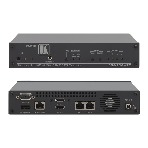
Overview The VM-114H2C 2 Input 1:4 HDMI DA/2x CAT5 Outputs is a switcher/distribution amplifier for HDMI and TP (twisted pair) signals. It reclocks and equalizes one of two selectable input signals and distributes it to two HDMI and two TP outputs. -
Page 8: Using Twisted Pair Cable
Using Twisted Pair Cable Kramer engineers have developed special twisted pair cables to best match our digital twisted pair products; the Kramer: BC-DGKat524 (CAT 5 24 AWG), the Kramer: BC-DGKat623 (CAT 6 23 AWG cable), and the Kramer: BC-DGKat7a23 (CAT 7a 23 AWG cable). These specially built cables significantly outperform regular CAT 5 / CAT 6 / CAT 7a cables. - Page 9 Inputs Connect to an HDMI source Input HDMI Connector IN2 (CAT5) Connect to a TP source (for example, PT-571 HDMI Input RJ-45 Line Transmitter, VM-114H2C or VM-114H4C) Connector OUT 1 HDMI Connect to the HDMI acceptors Output OUT 2 Connectors...
-
Page 10: Connecting The Vm-114H2C
4 (see Section .1). 7. Connect the power adapter to the power socket on the VM-114H2C and to the mains electricity (not shown in Figure 8. Optional—Press the EDID READ button to acquire or change the EDID 5... -
Page 11: Connecting To The Vm-114H2C Via Rs-232
Figure 2: Connecting the VM-114H2C 2 Input 1:4 HDMI DA/2x CAT5 Outputs Connecting to the VM-114H2C via RS-232 You can connect to the VM-114H2C via an RS-232 connection using, for example, a PC. Note that a null-modem adapter/connection is not required. -
Page 12: Operating The Vm-114H2C
Acquiring the EDID Section 9 Each input on the VM-114H2C has a factory default EDID loaded (see This lets you connect the power before having to connect one of the acceptors. The VM-114H2C reads the EDID, which is stored in the non-volatile memory. -
Page 13: Disabling/Enabling Deep Color Support
Section RS-232 and IR Control and Pass-Through The VM-114H2C can be controlled via RS-232 and infrared. Depending on how the RS-232 and IR connections are configured, the device either responds to control signals or transparently passes them through to another receiver or ... -
Page 14: Figure 3: Vm-114H2C Rs-232 Control And Pass-Through
5.3.2 Local IR Control and IR Pass-Through Using the VM-114H2C The VM-114H2C provides an IR sensor and a 3.5mm mini jack for connecting a remote IR emitter or sensor. When the VM-114H2C is connected to suitable transmitters and receivers (for example, the TP-573 and TP-574), the VM-114H2C can act as a pass-through for IR control signals, allowing remote control of multiple devices using multiple IR remote controllers. -
Page 15: Figure 4: Vm-114H2C Ir Control And Pass-Through Example 1
An LCD display is connected to the TP-574 receiver via an IR emitter. Both the TP-573 and the TP-574 are connected to the VM-114H2C via TP cabling. Point the appropriate remote control for the device at the VM-114H2C IR sensor to control a device. VM-114H2C - Operating the VM-114H2C... -
Page 16: Figure 5: Vm-114H2C Ir Control And Pass-Through Example 2
An LCD display is connected to the TP-574 receiver via an IR emitter. Both the TP-573 and the TP-574 are connected to the VM-114H2C via TP cabling. Point the LCD display remote control either at the TP-573 IR sensor or at the VM-114H2C IR sensor to control the LCD display. -
Page 17: Figure 6: Vm-114H2C Ir Control And Pass-Through Example 3
The first DVD player (player 1) is connected to the TP-573 transmitter via an IR emitter. The second DVD player (player 2) is connected to the VM-114H2C via an IR emitter. An IR sensor is connected to the TP-574 receiver. -
Page 18: Wiring The Twisted Pair Rj-45 Connectors
Green / White Blue Blue / White Green Brown / White Brown Pair 1 4 and 5 Pair 2 1 and 2 Pair 3 3 and 6 Pair 4 7 and 8 VM-114H2C - Wiring the Twisted Pair RJ-45 Connectors... -
Page 19: Technical Specifications
21.5cm x 16.3cm x 4.4cm (8.5in x 6.4in x 1.7in) W, D, H WEIGHT: 0.9kg (1.98lbs) approx. ACCESSORIES: Power supply, RC-IR3 infrared remote control transmitter RK-1 19” rack adapter OPTIONS: Specifications are subject to change without notice at http://www.kramerelectronics.com VM-114H2C - Technical Specifications... -
Page 20: Default Communication Parameters
The following table lists the default communication parameters for the VM-114H2C. RS-232 Protocol 2000 Baud Rate: 9600 Data Bits: Stop Bits: Parity: None Command Format: Example (Output 1 to Input 1): 0x01, 0x81, 0x81, 0x81 VM-114H2C - Default Communication Parameters... -
Page 21: Default Edid
1024 x 768p at 75Hz - VESA 1280 x 1024p at 75Hz - VESA 1280 x 1024p at 60Hz - VESA STD 1600 x 1200p at 60Hz - VESA STD 1152 x 864p at 75Hz - VESA ST VM-114H2C - Default EDID... -
Page 22: Protocol 2000
The default data rate is 9600 baud, with no parity, 8 data bits and 1 stop bit. Note: Compatibility with Kramer’s Protocol 2000 does not mean that a machine uses all of the commands below. Each machine uses a sub-set of Protocol 2000, according to its needs. - Page 23 For example, instruction 1 (SWITCH VIDEO) causes all units (including audio, data, etc.) to switch. Similarly, if a machine is in FOLLOW mode, it performs any video instruction. VM-114H2C - Protocol 2000...
- Page 25 For the latest information on our products and a list of Kramer distributors, visit our Web site where updates to this user manual may be found. We welcome your questions, comments, and feedback. Web site: www.kramerelectronics.com E-mail: info@kramerel.com SAFETY WARNING...
Need help?
Do you have a question about the VM-114H2C and is the answer not in the manual?
Questions and answers