
Subscribe to Our Youtube Channel
Related Manuals for Radyne DMD2050


Summary of Contents for Radyne DMD2050
-
Page 1: Installation And Operation Manual
DMD2050 Universal Satellite Modem Installation and Operation Manual TM110 Revision 1.3 Radyne Inc. • 3138 E. Elwood St. • Phoenix, AZ 85034 • (602) 437-9620 • Fax: (602) 437-4811 • www.radn.com... -
Page 3: Warranty Policy
Unless otherwise agreed, failure shall be deemed to have occurred no more than seven (7) working days before the first date on which Radyne Inc. receives a notice of failure. Under no circumstances shall any warranty exceed the period stated above unless expressly agreed to in writing by Radyne Inc. - Page 4 Radyne Inc.’s liability for damages shall not exceed the payment, if any, received by Radyne Inc. for the unit or product or service furnished or to be furnished, as the case may be, which is the subject of claim or dispute.
-
Page 5: Preface
DMD2050 Universal Satellite Modem Preface Preface This manual provides installation and operation information for the Radyne DMD2050 Universal Satellite Modem. This is a technical document intended for use by engineers, technicians, and operators responsible for the operation and maintenance of the DMD2050. -
Page 6: Trademarks
©2006, Radyne Inc. This manual is proprietary to Radyne Inc. and is intended for the exclusive use of Radyne Inc.’s customers. No part of this document may in whole or in part, be copied, reproduced, distributed, translated or reduced to any electronic or magnetic storage medium without the express written consent of a duly authorized officer of Radyne Inc. -
Page 7: Table Of Contents
2.0 Installation Requirements ___________________________________________ 2-1 2.1 Unpacking _______________________________________________________ 2-2 2.2 Removal and Assembly ____________________________________________ 2-2 2.3 Mounting Considerations ___________________________________________ 2-3 2.4 DMD2050 Initial Configuration Check __________________________________ 2-3 2.5 Modulator Checkout _______________________________________________ 2-4 2.5.1 Initial Power-Up _________________________________________________ 2-5 2.5.2 Factory Terminal Setup ___________________________________________ 2-5 2.6 Storage _________________________________________________________ 2-5... - Page 8 DMD2050 Universal Satellite Modem Section 3 - Theory of Operation ................3-1 3.0 DMD2050 Hardware _______________________________________________ 3-1 3.0.1 DMD2050 L-Band/IF Printed Circuit Card _____________________________ 3-1 3.0.2 DMD2050 Baseband Processing Printed Circuit Card____________________ 3-2 3.0.3 Enhanced Interface Printed Circuit Card ______________________________ 3-4 3.1 DMD2050 Functional Block Diagram __________________________________ 3-4...
- Page 9 3.14.1 Reed-Solomon Operation in the DMD2050 __________________________ 3-21 3.14.2 Reed-Solomon Code Rate _______________________________________ 3-21 3.14.3 Interleaving___________________________________________________ 3-21 3.15 DMD2050 Automatic Uplink Power Control (AUPC Operation) ____________ 3-22 3.16 Asynchronous Overhead Operation (Framing/Multiplexer Capability) _______ 3-24 3.17 Standard IBS Mode______________________________________________ 3-25 3.18 Asynchronous Multiplexer Mode ___________________________________ 3-26...
- Page 10 Case 2: IBS 1.544 Mbps, 3/4 Rate Viterbi _____________________________ 4-44 Case 3: Closed Network, 3/4 Rate Viterbi, IBS Overhead _________________ 4-45 Case 4: Loop Timing Example ______________________________________ 4-46 4.6 Configuring the DMD2050 for Drop and Insert __________________________ 4-46 4.6.1 Data Rate_____________________________________________________ 4-47 4.6.2 Operational Network Specification __________________________________ 4-47 4.6.3 Terrestrial Framing - Drop Mode/Insert Mode _________________________ 4-48...
- Page 11 4.11 Connecting the Terminal __________________________________________ 4-61 4.12 Terminal Screens _______________________________________________ 4-61 Section 5 - Rear Panel Interfaces ................5-1 5.0 DMD2050 Connections _____________________________________________ 5-1 5.1 Compact Flash ___________________________________________________ 5-3 5.2 Power Input Modules ______________________________________________ 5-3 5.2.1 AC Power Input Module ___________________________________________ 5-3 5.2.2 DC Power Input/Switch ___________________________________________ 5-3...
- Page 12 Table of Contents DMD2050 Universal Satellite Modem 5.4.3 8K DATA (J3) ___________________________________________________ 5-8 5.4.4 G.703 BAL (J4) _________________________________________________ 5-9 5.4.5 SWITCH INTERFACE (J5) ________________________________________ 5-9 5.4.6 SD (DDI) (J6) __________________________________________________ 5-12 5.4.7 DDO (J7) _____________________________________________________ 5-12 5.4.8 IDI (J8) _______________________________________________________ 5-12 5.4.9 SD (IDO) (J9) __________________________________________________ 5-12...
- Page 13 7.1 Modulator _______________________________________________________ 7-1 7.2 Demodulator _____________________________________________________ 7-2 7.3 Plesiochronous Buffer ______________________________________________ 7-2 7.4 Monitor and Control________________________________________________ 7-2 7.5 DMD2050 Drop and Insert (Optional) __________________________________ 7-2 7.6 Terrestrial Interfaces _______________________________________________ 7-3 7.7 IDR/ESC Interface (Optional) ________________________________________ 7-3 7.8 IBS/Synchronous Interface (Standard) _________________________________ 7-3 7.9 High-Speed Serial Interface (HSSI) ___________________________________ 7-3...
- Page 14 Table of Contents DMD2050 Universal Satellite Modem 7.18 DMD2050 BER Specifications ______________________________________ 7-9 7.18.1 BER Performance (Viterbi)________________________________________ 7-9 7.18.2 BER Performance (Sequential) ___________________________________ 7-10 7.18.3 BER Performance (Viterbi with Reed-Solomon) ______________________ 7-11 7.18.4 BER Performance (Turbo) _______________________________________ 7-12 7.18.5 BER Performance (8PSK Trellis) __________________________________ 7-13 7.18.6 BER Performance (8PSK Turbo) __________________________________ 7-14...
- Page 15 DMD2050 Universal Satellite Modem Table of Contents Appendix B - Front Panel Upgrade Procedure............B-1 B.0 Introduction ______________________________________________________ B-1 B.1 Required Equipment _______________________________________________ B-1 B.2 Upgrade Procedure _______________________________________________ B-1 B.3 Demonstration Procedure___________________________________________ B-3 B.3.3 Running in Demonstration Mode ____________________________________ B-5 B.3.4 Canceling Demonstration Mode ____________________________________ B-6...
- Page 16 Table of Contents DMD2050 Universal Satellite Modem TM110 - Rev. 1.3...
-
Page 17: Section 1 - Introduction
Radyne 's DMD50, DMD2401, DMD15, and DISA certified MIL-188-165 compliant DMD15L are maintained for seamless substitution and addition to existing systems. A full range of Industry Standard Interfaces is available for the DMD2050. Interface types are selectable from MIL-188-114A, ITU G.703, HSSI, ASI, DVB/M2P and Ethernet Bridge. -
Page 18: Dmd2050 Configurations
Only authorized service personnel should handle and install optional hardware options. 1.1.4 Radyne Installed Options Units may also be sent to the Radyne Inc. facility for hardware option installation. Please contact the Radyne Inc. Customer Service Department for information not limited to availability and to shipping costs. - Page 19 DMD2050 Universal Satellite Modem Introduction TM110 – Rev. 1.3...
-
Page 20: Section 2 - Installation
This section provides instructions on unpacking and installation, as well as storage of the unit. 2.0 Installation Requirements The DMD2050 Modem is designed to be installed within any standard 19-inch (48.26 cm) wide equipment cabinet or rack. It requires 1 rack unit (RU) of mounting space (1.75 inches/4.45 cm) vertically and 19.25 inches (48.89 cm) of depth. -
Page 21: Unpacking
• Installation and Operation Manual 2.2 Removal and Assembly The DMD2050 Modem Unit is shipped fully assembled. It does not require removal of the covers for any purpose in installation. Always ensure that power is removed from the DMD2050 before removing or installing any optional modules. -
Page 22: Mounting Considerations
Do not mount the DMD2050 in an unprotected outdoor location where there is direct contact with rain, snow, wind or sun. The only tools required for rack mounting the DMD2050 are four (4) customer supplied rack-mounting screws and the appropriate screwdriver. Rack mounting brackets are an integral part of the front bezel of the unit and are not removable. -
Page 23: Modulator Checkout
Cable from J1 to J2 on the rear panel of the modem. 2.5 Modulator Checkout The following descriptions assume that the DMD2050 is installed in a suitable location with prime AC power and supporting equipment available. TM110 - Rev. 1.3... -
Page 24: Initial Power-Up
DMD2050 Universal Satellite Modem Installation 2.5.1 Initial Power-Up Before initial power up of the DMD2050, it is a good idea to disconnect the transmit output from the operating ground station equipment. This is especially true if the current Modulator Configuration Settings are... - Page 25 Installation DMD2050 Universal Satellite Modem TM110 - Rev. 1.3...
-
Page 26: Section 3 - Theory Of Operation
L-Band/IF Assembly and a Digital Baseband Assembly. The optional printed circuit cards include a Turbo Codec printed circuit card and one of several types of Interface printed circuit card (refer to Appendix A). A block diagram of the DMD2050 is shown in Figure 3-1. -
Page 27: Dmd2050 Baseband Processing Printed Circuit Card
AGC. The gain-controlled signal is then passed through a complex downconverter to a low IF. 3.0.2 DMD2050 Baseband Processing Printed Circuit Card The advent of million-plus gate count FPGAs, advanced logic synthesis tools, and DSPs providing hundreds of MIPs enabled the design of a software configurable modem. Large, fast FPGAs now provide designers with what is essentially an on the fly programmable ASIC. - Page 28 DMD2050 Universal Satellite Modem Theory of Operation The DMD2050 Baseband Processing Printed Circuit Card provides a flexible architecture that allows many different modes of terrestrial and satellite framing, various FEC options, digital voice processing, and several different modulation/demodulation formats. Also included on the Baseband Printed Circuit Card are three synchronous interfaces, an EIA-530 Interface supporting MIL-188-114A and RS-422.
-
Page 29: Enhanced Interface Printed Circuit Card
The M&C System is based on a powerful microprocessor with a large amount of Flash memory. Several bus architectures are used to interconnect the M&C to all components of the DMD2050. Communication to the outside world is done via connections to the remote port, terminal port, Ethernet port, and alarm ports. -
Page 30: Tx Baseband Processing
DMD2050 Universal Satellite Modem Theory of Operation Figure 3-4. DMD2050 Universal Satellite Modem Functional Block Diagram 3.1.3 Tx Baseband Processing The Tx Data and Clock enters the Baseband Processor, passes through a Rate Adapting FIFO and enters the Framer/Drop Processor. In Closed-Net Mode, the data passes through the framer unaltered. -
Page 31: Rx Baseband Processing
Theory of Operation DMD2050 Universal Satellite Modem 3.1.4 Rx Baseband Processing The Receive Processor performs the inverse function of the Tx Processor. Data received from the satellite passes through the BB Loopback Circuit to the Reed-Solomon Decoder to the Deframer. The Deframer acquires the IBS/IDR/DVB frame, synchronizes the Reed-Solomon Decoder and extracts the received data and overhead from the frame structure, placing the data into the PD Buffer, sending the overhead data to the UIM. -
Page 32: Earth Station To Earth Station Communications Port
DMD2050 Universal Satellite Modem Theory of Operation 3.2 Earth Station to Earth Station Communications Port The modem contains a selectable RS-232, or RS-485 Asynchronous Communications Port for Earth Station-to-Earth Station Communications. The baud rate and protocol can be selected from the Front Panel. -
Page 33: Baseband Processing
Theory of Operation DMD2050 Universal Satellite Modem 3.5.1 Baseband Processing The Baseband Processor performs all of the functions required for an IBS/IDR Framing Unit, a Reed-Solomon Codec, an E1/T1 Drop and Insert System, a Turbo Codec, and Sequential/Viterbi. In addition, the Baseband Processing Section provides for Transmit clock selection and rate adaptation as well as a rate adapter and Plesiochronous/Doppler (PD) Buffer in the receive direction. - Page 34 DMD2050 Universal Satellite Modem Theory of Operation Figure 3-7. Loopback Functional Block Diagram Figure 3-8. Loopback Functional Block Diagram TM110 – Rev. 1.3...
-
Page 35: Dmd2050 Clocking Options
3.6 DMD2050 Clocking Options The following paragraphs define the types of clocking options available to the user at the Front Panel of the DMD2050. Refer to Figure 3.9 for clocking and polarity. 3.6.1 Clock Selection As shown in Figure 3-9, both the Tx Clock and the Buffer Clock source may be independently locked. -
Page 36: Scte: Serial Clock Transmit External
DMD2050 Universal Satellite Modem Theory of Operation 3.6.2 SCTE: Serial Clock Transmit External This clock is the Transmit Terrestrial Clock associated with the interface. With the G.703 Interface selected, SCTE is the clock that is recovered from the G.703 data stream. SCTE is sometimes referred to as Tx Terrestrial Timing and for Synchronous Interfaces such as RS-422, SCTE is sometimes referred to as TT (Terminal Timing). -
Page 37: Ext If Ref: External If Reference
This is not actually a clock, but does have some clocking implications. When the external reference is used, the master oscillator within the DMD2050 is locked to the external reference, and the internal accuracy and stability of the DMD2050 assumes that of the External Reference. -
Page 38: Transmit (Mil-188-114A, Rs-422)
Select the Buffer clock to RxSAT (SCR). 3.10 Drop and Insert (D&I) The Radyne DMD2050 Drop and Insert (D&I) function provides an interface between a full T1 or E1 Trunk whose framing is specified in CCITT G.704 and a fractional Nx64 Kbps Satellite Channel that conforms to the IBS and small IDR Framing Structures. - Page 39 Theory of Operation DMD2050 Universal Satellite Modem Figure 3-10. Looped Modems Figure 3-11. Looped Modems with Separate D&I Trunks 3-14 TM110 - Rev. 1.3...
-
Page 40: Drop Only
Figure 3-12. Drop Only 3.10.2 Insert Only When Insert is enabled and Drop is disabled, the DMD2050 performs an insert-only function. If framed terrestrial E1 or T1 Data is available, it should be input via the Insert Data In Port. The Terrestrial Data is buffered inside the Modem. -
Page 41: Mode Selection
Figure 3-14. Insert Only with Internal Frame Source 3.11 Mode Selection The DMD2050 D&I can be easily configured to support several commonly used terrestrial data formats. For E1 Data, the user can choose between PCM-30, PCM-30C, PCM-31 and PCM-31C. For T1 Data, the user can choose between T1-D4, T1-ESF, and SLC-96. The following paragraphs provide more information on the various mode selection capabilities of the DMD2050. -
Page 42: Pcm-31C
= 1, 2, 3, 4, 5, 6, 8, 10, 12, 15, 16, 20, 24, or 30. In the DMD2050, Robbed Bit Signaling (RBS) is handled without any need for operator intervention and is transparent to the user. -
Page 43: Drop And Insert Mapping
Theory of Operation DMD2050 Universal Satellite Modem 3.13 Drop and Insert Mapping The following displays under Interface D&I Setup (both Tx and Rx), are editing displays only: SATCh Enter to Edit Any changes made in these displays are made on the screen, but are not entered into the modem. - Page 44 DMD2050 Universal Satellite Modem Theory of Operation Example: For a modem w/ Drop & Insert enabled at a data rate of 256 (with timeslots assigned 1 - 1, 2 - 2, etc.). At a data rate of 256, the modem will allow 4 channels to assign timeslots. Under the Tx Menu, assign the timeslots that are to be used to the 4 channels.
-
Page 45: Reed-Solomon Codec
Theory of Operation DMD2050 Universal Satellite Modem To View the current Timeslot Assignment: If there is a question of the channels not being entered properly, the Mapping Menu may be used to see how the channels/timeslots are configured in the modem. -
Page 46: Reed-Solomon Operation In The Dmd2050
Appendix A for further information. 3.14.3 Interleaving The DMD2050 allows for interleaving depths of 4 or 8 R-S Blocks. This allows burst errors to be spread over 4 or 8 R-S blocks in order to enhance the error correcting performance of the R-S Codec. -
Page 47: Dmd2050 Automatic Uplink Power Control (Aupc Operation)
2. Design objective. 3.15 DMD2050 Automatic Uplink Power Control (AUPC Operation) The DMD2050 Modem has an optional built-in provision for Automatic Uplink Power Control (AUPC). AUPC attempts to maintain a constant E at the receive end of an SCPC link. This is especially useful when operating over a satellite at Ku-Band Frequencies in locations with high rainfall periods. - Page 48 DMD2050 Universal Satellite Modem Theory of Operation The IBS Async Framer Data Mode provides a service channel between the two sites of a link permitting the modem processors to send messages and get responses over this channel. AUPC can be set to operate on either or both directions of a link but always requires a bi-directional channel.
-
Page 49: Asynchronous Overhead Operation (Framing/Multiplexer Capability)
Theory of Operation DMD2050 Universal Satellite Modem 3.16 Asynchronous Overhead Operation (Framing/Multiplexer Capability) The Asynchronous Framing/Multiplexer is capable of multiplexing a relatively low-speed overhead channel onto the terrestrial data stream resulting in a slightly higher combined or aggregate data rate through the modem. The overhead channel is recovered at the far end. This added channel is termed variously “An Overhead Channel”, ”Service Channel”, “Async Channel”... -
Page 50: Standard Ibs Mode
DMD2050 Universal Satellite Modem Theory of Operation 2048 1024 19200 19200 19200 1024 19200 1088 19200 1152 19200 1216 19200 1280 19200 1344 19200 1408 19200 1472 19200 1536 19200 1600 19200 1664 19200 1728 19200 1792 19200 1856 19200... -
Page 51: Asynchronous Multiplexer Mode
DMD2050 is at both ends of a link. In this mode, the overhead signaling bytes 16 and 48 can be used to implement a significantly higher speed ES to ES Data Channel under software control. -
Page 52: To Disable The Esc Backward Alarms
DMD2050 Universal Satellite Modem Theory of Operation 3.19.1 To Disable the ESC Backward Alarms If the ESC ALARMS Port will not be used and the Backward Alarm Indications are to be disabled, you will need to connect pins 19, 11, 22 and 23 to pin 1 (Gnd). -
Page 53: Aggregate Data Rate
Theory of Operation DMD2050 Universal Satellite Modem The Control Ratio of the receiving units must match the Control Ratio of the transmitting unit. 3.20.2 Aggregate Data Rate The aggregate data rate equals the following: User Data Rate + In-Band Rate + Synchronizing Overhead Rate Because SCC must adjust the overhead so that there are an equal number of user data bits in each slot, the synchronizing overhead cannot be easily calculated. -
Page 54: Actual Overhead Rate Calculation
DMD2050 Universal Satellite Modem Theory of Operation User Data In-Band Control Aggregate Data Overhead Rate Rate Ratio Rate Ratio 512,000 19,200 533,974 1.043 1,024,000 19,200 1,045,974 1.021 2,048,000 19,200 2,069,951 1.011 3,072,000 19,200 3,093,943 1.007 4,096,000 19,200 4,117,951 1.005 6,312,000... -
Page 55: Scc Overhead Channel Setup
This allows the user to choose between 7 or 8 bits of data. Repeat Steps 4 through 7 under the RX ASYNC MODE (menu) The physical connection to the DMD2050 for the overhead channel will be the DB-9 Female Port labeled ASYNC (J17). -
Page 56: Locating The Dmd2050 Id Code Operational Procedure
Users are required to identify these ID codes when they want additional features added to their unit. Radyne will supply a new ID code that is required to be entered in the ID code field. Once the new ID code is entered, the modem will activate the new features. - Page 57 Theory of Operation DMD2050 Universal Satellite Modem 3-32 TM110 - Rev. 1.3...
-
Page 58: Section 4 - User Interfaces
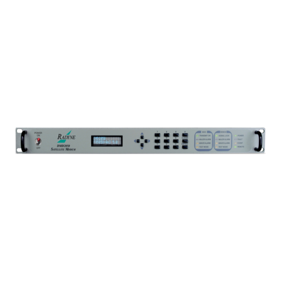
Terminal Interface. 4.1 Front Panel User Interface The Front Panel of the DMD2050 allows for complete control and monitor of all DMD2050 parameters and functions via a keypad, VFD (Vacuum Flourescent Display) and status LEDs. The front panel layout is shown in Figure 4-1, showing the location and labeling of the front panel. -
Page 59: Vfd Front Panel Display
User Interfaces DMD2050 Universal Satellite Modem 4.1.1 VFD Front Panel Display The front panel display is a 2 line by 16-character vacuum flourescent display. The display is lighted and the brightness can be set to increase when the front panel is currently in use. The VFD automatically dims after a period of inactivity. -
Page 60: Front Panel Led Indicators
User Interfaces 4.1.4 Front Panel LED Indicators Eight LEDs on the DMD2050 Front Panel (Refer to Table 4-3) indicate the status of the DMD2050’s operation. The LED colors maintain a consistent meaning. Green signifies that the indication is appropriate for normal operation, Yellow means that there is a condition not proper for normal operation, and Red indicates a fault condition that will result in lost communications. -
Page 61: Front Panel Control Screen Menus
DMD2050 Universal Satellite Modem Figure 4-2. Entering New Parameters Following a valid input, the DMD2050 will place the new setting into the nonvolatile EEPROM making it available immediately and available the next time the unit is powered-up. 4.3 Front Panel Control Screen Menus The DMD2050 Front Panel Control Screens are broken down into sections under several Main Menus. -
Page 62: Modulator Menu Options And Parameters
DMD2050 Universal Satellite Modem User Interfaces 4.3.2 Modulator Menu Options and Parameters NETWORK SPEC {MIL 188-165A, IDR, IBS, DROP & INSERT, CLOSED NET, DVB} Used with IDR, or IBS Interface Only. The Network Spec Command sets a number of parameters within the modem to meet a set specification. - Page 63 User Interfaces DMD2050 Universal Satellite Modem DVB: EN301-201 and EN300-421 Data Rates: All Rates Framing Type: Scrambler Type: Spectrum Mask: DVB 0.25, 0.35 Closed Net: All possible combinations allowed, however, DVB settings requires the DVB network spec. STRAP CODE {Refer to Strap Code Guide, Table 4-4} The Strap Code is a quick set key that sets many modem parameters.
- Page 64 Allows the user to select the Tx Code Rate and Type. TPC INTERLEAVER {DISABLE, ENABLE} Allows the user to disable or enable the TPC Interleaver. Valid only on Radyne Turbo Codes TPC .495 and TPC .793. DIFF CODING {ENABLED, DISABLE} Allows the user to enable or disable the Differential Encoder.
- Page 65 User Interfaces DMD2050 Universal Satellite Modem SAT FRAMING {1/15 (IBS), 1/15 (Async), 96 Kbps (IDR), DVB, EDMAC, EFAUPC, SCC, NONE, EFFICIENT D&I} Used with IDR, IBS, or Asynchronous Interface Only. Allows the user to select the framing type. When SCC Framing is selected above, the following two screens are available.
- Page 66 DMD2050 Universal Satellite Modem User Interfaces Displays the AUPC Mode. AUPC Eb/No {4 to 20dB} Allows the user to enter the target Eb/No value. AUPC MIN LVL {0 to -25dB} Allows the user to set the minimum Transmit Power. The minimum Transmit Power is the lowest power setting that will be used when the remote modem commands a decrease of the Transmit Power.
- Page 67 User Interfaces DMD2050 Universal Satellite Modem setting that will be used when the remote modem commands an increase of the Transmit Power. It is the setting that will be used when the remote modem indicates that its receiver has lost lock and commands a change to the setting indicated in the 'REMOTE CL ACTION’, Menu.
-
Page 68: Demodulator Menu Options And Parameters
DMD2050 Universal Satellite Modem User Interfaces TX 2047 PATTERN Allows the user to enable or disable the Transmit 2047 Pattern Test Mode of the remote modem. REMOTE AUPC MONITOR The ‘REMOTE AUPC MONITOR’ Menu contains the remote monitor status for the AUPC Function. - Page 69 User Interfaces DMD2050 Universal Satellite Modem IDR: (IESS-308) For Data rates 1.544, 2.048, 6.312, 8.448 Mbps Framing Type: 96 Kbps (IDR) Descrambler type: V.35 Spectrum Mask: Intelsat For Data Rates < 1.544 Mbps Framing Type: 1/15 (IBS) Descrambler Type: IESS-309...
- Page 70 DMD2050 Universal Satellite Modem User Interfaces IF (menu) FREQUENCY (MHz) {50 – 90 MHz, 100 – 180 MHz, or 950 - 2050 MHz} Allows the user to enter the Modulator IF Frequency in 1 Hz increments. SPECTRUM {NORMAL INVERTED} Allows the user to invert the direction of rotation for PSK Modulation.
- Page 71 Allows the user to select the Rx Code Rate and Type. TPC INTERLEAVER {DISABLE, ENABLE} Allows the user to disable or enable the TPC Interleaver. Valid only on Radyne Turbo Codes TPC .495 and TPC .793. DIFF CODING {ENABLED, DISABLE} Allows the user to enable or disable the Differential Decoder.
- Page 72 DMD2050 Universal Satellite Modem User Interfaces When SCC Framing is selected above, the following two screens are available. SCC CTL RATIO {1/1, 1/2, 1/3, 1/4, 1/5, 1/6, 1/7} Only available when using SCC framing. Allows the user to simulate the framing used by the Satellite Control Channel Option (Pass Thru Mode only).
-
Page 73: Interface Menu Options And Parameters
User Interfaces DMD2050 Universal Satellite Modem 4.3.4 Interface Menu Options and Parameters TX SETUP (menu) CIRCUIT ID Allows the user entry of a Tx Circuit Identifier. Circuits can be given up to an 11 Character alphanumeric identity such as LINK1. - Page 74 DMD2050 Universal Satellite Modem User Interfaces SAT CH TERRCH Allows the user to edit the Tx edit map to specify the terrestrial slots that will be dropped into assigned satellite channels. The satellite channels are fixed ane the number of channels are determined by the data rate.
- Page 75 User Interfaces DMD2050 Universal Satellite Modem BUFFER CLOCK POL {NORMAL, INVERTED} Allows the user to select the Buffer Clock Polarity for the Tx Terrestrial Clock relative to the Tx Data. If G.703 Interface is selected, this selection cannot be changed.
-
Page 76: Aupc Menu Options And Parameters
DMD2050 Universal Satellite Modem User Interfaces Overhead Signaling bytes in the IBS Overhead to pass asynchronous data. ES INTERFACE {RS-232, RS-485} Allows the user to select the interface type. ES BITS/CHAR {7,8} Allows the user to choose between 7 or 8 bit data. - Page 77 User Interfaces DMD2050 Universal Satellite Modem EBNO (dB) Displays the estimated E as seen by the demodulator. RAW BER Displays the estimated channel error rate (before decoding) measured by the modem. CORRECTED BER The CBER display shows an estimated corrected bit error rate of the modem.
-
Page 78: Alarms Menu Options And Parameters
DMD2050 Universal Satellite Modem User Interfaces PORT 1 STATUS {See the note above} Displays the current status of LAN Port 1. PORT 2 STATUS {See the note above} Displays the current status of LAN Port 2. PORT 3 STATUS {See the note above} Displays the current status of LAN Port 3. - Page 79 User Interfaces DMD2050 Universal Satellite Modem Masking alarms may cause undesirable modem performance. CURRENT ALARMS (menu) TX MAJOR (menu) Status Edit Table FPGA CFG {Pass/Fail, Unmasked/Masked} Indicates a transmit FPGA configuration failure. DSP CFG {Pass/Fail, Unmasked/Masked} Indicates a transmit DSP configuration failure.
- Page 80 DMD2050 Universal Satellite Modem User Interfaces TX TERR AIS {Pass/Fail, Unmasked/Masked} Indicates that AIS has been detected in the Tx Data Stream. DnI FRAME LOCK {Pass/Fail, Unmasked/Masked} Indicates that the TX Oversample Clock PLL is not locked. This alarm will flash on during certain modem parameter changes.
- Page 81 User Interfaces DMD2050 Universal Satellite Modem changes. A solid indication points toward a configuration problem within the modem. ETHERNET WAN Indicates that the interface card is faulted and will not pass data (displays only when the Ethernet Card is installed and the Ethernet Interface is selected).
- Page 82 DMD2050 Universal Satellite Modem User Interfaces RS UNCORR {Pass/Fail, Unmasked/Masked} Indicates status of the Reed-Solomon uncoded word fault. TPC IFC LOCK {Pass/Fail, Unmaskd, Masked} EBNO (dB) {Pass/Fail, Unmasked/Masked} Indicates that the Eb/No is outside of limits. RX AGC LEVEL {Pass/Fail, Unmasked, Masked} Indicates Rx level is below allowable limts.
- Page 83 User Interfaces DMD2050 Universal Satellite Modem +20V SUPPLY {Pass/Fail, Unmasked/Masked} Displays the measured voltage of the +20 Volt power bus located inside the modem. EXT CLOCK ACT {Pass/Fail, Unmasked/Masked} Indicates that the External Clock is not active. EXT REF ACT {Pass/Fail, Unmasked/Masked} Indicates no activity on the External Reference.
- Page 84 DMD2050 Universal Satellite Modem User Interfaces DnI M-FRAME LOCK DROP CRC TX DVB FRM LOCK RX MAJOR (menu) FPGA CFG DSP CFG SIGNAL LOCK FRAME LOCK MULTIFRAME LOCK LB SYNTH PLL IF SYNTH PLL ETHERNET WAN RX MINOR (menu) BUFF UNDERFLOW...
- Page 85 User Interfaces DMD2050 Universal Satellite Modem EBNO RX LEVEL IBS BER RX DVB FRM LOCK COMMON (menu) TERR FPGA CFG CODEC FPGA CFG CODEC DEV CFG VOLTAGE (menu) +1.5V RX SUPPLY +1.5V TX SUPPLY +3.3V SUPPLY +5V SUPPLY +12V SUPPLY...
- Page 86 DMD2050 Universal Satellite Modem User Interfaces IDR BACKWARD 1 {RCV = NO/YES, FRC = NO/YES} IDR BACKWARD 2 {RCV = NO/YES, FRC = NO/YES} IDR BACKWARD 3 {RCV = NO/YES, FRC = NO/YES} IDR BACKWARD 4 {RCV = NO/YES, FRC = NO/YES} MAP SUMMARY {NONE, BK 1;...
-
Page 87: System Menu Options And Parameters
User Interfaces DMD2050 Universal Satellite Modem 4.3.8 System Menu Options and Parameters DATE (MM/DD/YY) Allows the user to enter the current date. TIME {HH:MM:SS} Allows the user to enter the current time. CONFIG COPY {CURRENT, CFG1….FG10} Allows the user to save and copy modem configurations. - Page 88 DMD2050 Universal Satellite Modem User Interfaces TCP/IP (menu) BOOT MODE {DEFAULT, NON-VOL, BOOTP} DEFAULT: During initialization (boot up), the modem will restore the web setting to the standard IP Mask and addresses supplied by the modem. The modem will be taken off the network and will not be accessible.
- Page 89 User Interfaces DMD2050 Universal Satellite Modem specified, the address is presumed to be reachable via the router. Broadcast and loop back addresses will not be allowed. These are addresses with all subnet bits set to 0’s or 1’s. ROUTER IP ADDR {XXX.XXX.XXX.XXX}...
- Page 90 DMD2050 Universal Satellite Modem User Interfaces TRAP VERSION {V1, V2} This controls the type of message format used when a message trap is generated by the equipment and bound for a SNMP Host. Messages will only be sent if the unit has been authorized to do so.
- Page 91 User Interfaces DMD2050 Universal Satellite Modem Admin: At this highest access right, the users can monitor and control the modems parameters, change any user’s name and authentication password, and modify IP network settings. Admin setting allows access to the entire site.
- Page 92 DMD2050 Universal Satellite Modem User Interfaces No Group: Denies Access Guest: Users are able to navigate most of the site, and view modem parameter settings. Oper: Users can monitor and and control parameter settings, change their authentication passwords. Admin: At this highest access right, the users can monitor and control the modems parameters, change any user’s name and authentication password, and...
- Page 93 TERR INTFC BRD Indicates the Radyne part number for the Terrestrial Interface Assembly. CODEC BOARD (menu) Indicates the Radyne part number for the Codec Board. TPC FPGA IMAGE Used for factory test only. RS FPGA IMAGE Used for factory test only.
-
Page 94: Test Menu Options And Parameters
DMD2050 Universal Satellite Modem User Interfaces TXIF TXLBAND ENH ASYNC RS CUSTOM D&I AUPC 8PSK 16QAM TURBO 52 MBPS EDMAC 4.3.9 Test Menu Options and Parameters TX TEST PATTERN {NONE, 2047, 2^15-1, 2^23-1} Allows the user to enable the tests listed above. -
Page 95: Dmd2050 Strap Codes
The Strap Code is a quick set key that sets many of the modem parameters. For quick setup of the DMD2050, Strap Codes are very helpful. When a Strap Code is entered, the modem is automatically configured for the code’s corresponding data rate, overhead, code rate, framing, scrambler type and modulation. - Page 96 DMD2050 Universal Satellite Modem User Interfaces Table 4-4. DMD2050 Strap Codes Dis = Disable 16/15 QPSK 16/15 QPSK 16/15 QPSK 16/15 QPSK 16/15 QPSK 16/15 QPSK 1536 16/15 QPSK 1920 16/15 QPSK 2048 16/15 QPSK 2048 QPSK 1544 V.35 (IESS)
- Page 97 User Interfaces DMD2050 Universal Satellite Modem NONE V.35 (IESS) QPSK NONE V.35 (IESS) QPSK NONE V.35 (IESS) QPSK NONE 1344 V.35 (IESS) QPSK NONE 1344 V.35 (IESS) QPSK NONE 1536 V.35 (IESS) QPSK NONE 1536 V.35 (IESS) QPSK NONE 1544 V.35 (IESS)
- Page 98 DMD2050 Universal Satellite Modem User Interfaces 16/15 QPSK 16/15 QPSK 16/15 QPSK 16/15 QPSK 16/15 QPSK 16/15 QPSK 16/15 QPSK 16/15 QPSK 16/15 QPSK 16/15 QPSK 16/15 QPSK 16/15 QPSK 16/15 QPSK 1024 16/15 QPSK 1024 16/15 QPSK 1536 16/15...
-
Page 99: Sample Dmd2050 Applications
QPSK 4.5 Sample DMD2050 Applications The following section provides brief application notes for operating the DMD2050 and explains by example how to configure the DMD2050 for some of the most popular configurations. The following information illustrates the allowable combinations for Mode and Data Rate for the DMD2050. -
Page 100: Operational Case Examples
DMD2050 Universal Satellite Modem User Interfaces 4.5.1 Operational Case Examples For best results always begin setup by setting the data rate to 512 Kbps. This data rate is applicable for all modes and as such provides a convenient launch point for setting up the modem. -
Page 101: Case 2: Ibs 1.544 Mbps, 3/4 Rate Viterbi
User Interfaces DMD2050 Universal Satellite Modem Demodulator: Method 1 - Set mode to IDR Under Demod IF Menu: Set desired Rx frequency Under Demod data Menu: Set code rate to 3/4 VIT Set data rate for 8448000 Under Interface Menu:... -
Page 102: Case 3: Closed Network, 3/4 Rate Viterbi, Ibs Overhead
DMD2050 Universal Satellite Modem User Interfaces Demodulator: Method 1 - Set Framing to 1/15: Set mode to IBS: Under Demod IF Menu: Set desired Rx frequency Under Demod Data Menu: Set code rate to 3/4 VIT Set data rate for 1544000... -
Page 103: Case 4: Loop Timing Example
Set SCT Source to SCR Set Tx Clock to SCTE 4.6 Configuring the DMD2050 for Drop and Insert Several dependencies exist when configuring the modem for Drop and Insert (D&I). The following paragraphs explain these dependencies and provide the user with the information required to ensure smooth transition into D&I and to minimize the potential impact of these... -
Page 104: Data Rate
DMD2050 Universal Satellite Modem User Interfaces 4.6.1 Data Rate Data Rate affects the Drop and Insert function in the following ways: • It determines the number of Satellite Channels that will be displayed in the Edit Maps. • It contributes to the Operational Mode selection process. Trying to change the Operational Mode to D&I when a data rate is not set to a valid D&I rate will result in... -
Page 105: Terrestrial Framing - Drop Mode/Insert Mode
User Interfaces DMD2050 Universal Satellite Modem 4.6.3 Terrestrial Framing - Drop Mode/Insert Mode The Drop Mode Selection and the Insert Mode Selection identify the Terrestrial Data-Framing Format. As previously mentioned, their selection is influenced by the Modulator and Demodulator Data Rates, and trying to select a T1 Type Framing Format with a data rate of 1920000 bps will result in an error message. -
Page 106: D&I Sample Configurations And D&I Clock Setup Options
DMD2050 Universal Satellite Modem User Interfaces 4.6.4 D&I Sample Configurations and D&I Clock Setup Options The following are several examples of how to configure the modem for D&I. Also, refer to Figures 3-14 through 3-17 for the D&I Clocking Setup Options Available. - Page 107 User Interfaces DMD2050 Universal Satellite Modem Example 2: Multidestinational Remote Site Programming Drop 512 Kbps from a T1 trunk, 3/4 Rate Viterbi. Extract 512 Kbps from a 1536 Kbps carrier and insert into a T1 trunk, 3/4 Rate Viterbi. Drop 512 Kbps from a T1 trunk, 3/4 Rate Viterbi Configuration setup is exactly as previously shown in Example 1.
- Page 108 DMD2050 Universal Satellite Modem User Interfaces Figure 4-4. Single Trunk Figure 4-5. Rx Only With Trunk Figure 4-6. Rx Only No Trunk TM110 – Rev. 1.3 4-51...
-
Page 109: D&I Maps And Map Editing
Maps always contain 30 entries, although, only the first “n” entries are relevant (see Table 4-5). The DMD2050 includes provisions to copy, change, and store the D&I transmit and receive maps directly from the Front Panel or via the remote M&C link. These maps are tables that are used to define and configure the D&I functions. - Page 110 DMD2050 Universal Satellite Modem User Interfaces ROM maps are read-only and may not be modified (refer to Table 4-6). Table 4-6. D&I ROM Maps T1/E1 Time Slot 9 10 11 12 10 11 12 9 10 11 12 13 14 15 16 17 18 19 20 21 22 23 24 25 26 27 28 29 30 9 10 11 12 13 14 15 17 18 19 20 21 22 23 24 25 26 27 28 29 30 31 Since the D&I Functions are separate and distinct, two separate maps must be configured at the...
- Page 111 User Interfaces DMD2050 Universal Satellite Modem The following paragraphs give examples of typical configurations that could use the ROM Maps as templates. The ROM Map used would have to be first copied to the appropriate Active Transmit (Drop) and/or Active Receive (Insert) Map(s) before it could be used. To use a modification of a ROM Map, the ROM Map must first be copied to the appropriate Edit Map, then modified, and then copied to the appropriate Active Map.
-
Page 112: Configuring The Modem To Use The Ethernet Data Interface (Optional)
DMD2050 Universal Satellite Modem User Interfaces ROM Map 6 could be used as the template for an Active Transmit (Drop) and/or Active Receive (Insert) Map with a modulator and/or demodulator configured for 768 Kbps operation. The T1 or E1 Data in the transmit path or the demodulated data in the receive path would be dropped from and or inserted into the first 12 time slots of the T1 or E1 frame. -
Page 113: Ethernet Flow Control
User Interfaces DMD2050 Universal Satellite Modem 4.8.1 Ethernet Flow Control When disabled, if a packet is received for transmission and no packet buffer space is available, the incoming packet is discarded. When enabled, flow control is used to throttle the transmission station in order to avoid overrunning the transmit buffers, which would in turn cause packets to be dropped. -
Page 114: Ethernet Qos Type
DMD2050 Universal Satellite Modem User Interfaces 4.8.3 Ethernet QOS Type When Normal QOS is selected, the interface determines a packets priority based on the following: IEEE 803.3ac Tag when present IPv4 Type of Service / Differentiated Services Field Ipv6 Traffic Class When Port Based QOS is selected, the interface determines the priority of a packed based upon the port on which it arrived. -
Page 115: Packet Statistics
User Interfaces DMD2050 Universal Satellite Modem 4.8.5 Setting Up The DMD20/DMD20 LBST Ethernet Bridge To Operate Like A FIFO In certain circumstances, it may be desirable to have the Ethernet interface operate in a FIFO like manner with no reordering of packets. This can be established by using a single port on the Ethernet interface and setting the Ethernet QOS Type to Port Based and the Ethernet QOS Queue to Strict Priority. -
Page 116: Terminal Mode Control
If the WAN Port is down, a Tx and Rx Ethernet WAN Major Alarm will be generated. 4.9 Terminal Mode Control The DMD2050 Terminal Mode Control allows the use of an external terminal or computer to monitor and control the modem from a full screen interactive presentation operated by the modem itself. -
Page 117: Modem Setup For Terminal Mode
Controls, Insert Controls, and Interface Areas. 4.10 Terminal Port User Interface The Remote Port (J20) of the DMD2050 allows for complete control and monitoring of all DMD2050 parameters and functions via an RS-232 Serial Interface, or RS-485 for RLLP Protocol. ‘Terminal Mode’ can be entered from the front panel by selecting “System” and then “Control Mode”... -
Page 118: Connecting The Terminal
DMD2050 Universal Satellite Modem User Interfaces 4.11 Connecting the Terminal Connect the computer to the DMD2050 Remote Connector (J20) on the rear of the unit using the RS-232 Cable. Enable the terminal by selecting Terminal Mode (located under the System - Control Mode Menu) from the front panel. - Page 119 User Interfaces DMD2050 Universal Satellite Modem 4-62 TM110 - Rev. 1.3...
-
Page 120: Section 5 - Rear Panel Interfaces
5.0 DMD2050 Connections All DMD2050 connections are made to labeled connectors located on the rear of the unit (refer to Figure 5-1). The connector definitions below are those on the DMD2050 unit. Any connection interfacing to the DMD2050 must be the appropriate mating connector. - Page 121 Rear Panel Interfaces DMD2050 Universal Satellite Modem Figure 5-1. DMD2050 Universal Satellite Modem Rear Panel Configurations TM110 - Rev. 1.3...
-
Page 122: Compact Flash
(#10-32 threaded stud), is located to the lower right of the module. 5.2.2 DC Power Input/Switch The Optional DC Power Input and Switch (Figure 5-1) is available for the DMD2050 products. The unit may be powered from a 48V ± 5VDC source with a maximum unit power consumption of 3 A. -
Page 123: Rx L-Band If (J14)
Rear Panel Interfaces DMD2050 Universal Satellite Modem 5.3.5 RX L-Band IF (J14) The Receive IF Input Port is a 50 Ohm SMA Female Connector that can be used for L-Band IF. The IF Frequency can be programmed from 950 to 2050 MHz in 1 Hz Steps. -
Page 124: Async (J17)
No Connect No Connect No Connect 5.3.9 TERMINAL (J18) Used for Radyne factory use only. 5.3.10 MIL-188-114A (J19) The EIA-530 Port is an RS-422 Connection. It is a 25-Pin Female “D” Connector. Refer to Table 5-4 for pinouts. Table 5-4. MIL-188-114A Port (RS-422) 25-Pin Female “D” Connector (J19) Pin No. -
Page 125: Remote (J20)
Rear Panel Interfaces DMD2050 Universal Satellite Modem Clear T Send B (+) CS-B Output Send Data B (+) SD-B Input Send Timing A (-) ST-A Output Receive Data B (+) RD-B Output Receive Timing A (-) RT-A Output Modulator Fault - Open Collector... -
Page 126: Idr/Ibs Interface (Optional)
DMD2050 Universal Satellite Modem Rear Panel Interfaces 5.4 IDR/IBS Interface (Optional) 5.4.1 ESC ALARM (J1) The ESC (Engineering Service Circuits) Alarms Port is a 25-Pin Female “D” Connector. Refer to Table 5-6 for pinouts. Table 5-6. ESC ALARM Port 25-Pin Female “D” Connector (J1) Pin No. -
Page 127: Audio (J2)
Rear Panel Interfaces DMD2050 Universal Satellite Modem 5.4.2 64K AUDIO (J2) The 64K AUDIO Port allows for communications between Earth Stations. It is a 9-Pin Female “D” Connector that complies to IESS 308. Refer to Table 5-7 for pinouts. Table 5-7. 64K AUDIO Port 9-Pin Female “D” Connector (J2) Pin No. -
Page 128: Bal (J4)
DMD2050 Universal Satellite Modem Rear Panel Interfaces 5.4.4 G.703 BAL (J4) The G.703 Interface Port (Balanced) is a 15-Pin Female “D” Connector. Refer to Table 5-9 for pinouts. Table 5-9. G.703 BAL Port 15-Pin Female “D” Connector (J4) Pin No. - Page 129 Rear Panel Interfaces DMD2050 Universal Satellite Modem IDR ESC Backward Alarm ESCBWO 1NO No Direction Out - 1 Normally Open Synchronous Data Terminal Timing SYNC TT-A Input Input – A IDR ESC Backward Alarm ESCBWO 2NC No Direction Out - 2 Normally Closed G.703 Drop Data Out A -...
- Page 130 DMD2050 Universal Satellite Modem Rear Panel Interfaces Synchronous Data Clear to SYNC CS-A Output Send - A IBS Receive Octet RXO-A Output Output - A Synchronous Data Request to SYNC RS-A Input Send - A Synchronous Data Receiver SYNC RR-A...
-
Page 131: Sd (Ddi) (J6)
Rear Panel Interfaces DMD2050 Universal Satellite Modem IDR ESC Backward Alarm ESCBWI 4 Input Input - 4 IBS ES Transmit Data – B TX-B BWI 2 Input IDR ESC Backward Alarm Input - 2 Demod Fault Open Collector DMD FLT... -
Page 132: High-Speed Serial Interface (Hssi) (Optional)
DMD2050 Universal Satellite Modem Rear Panel Interfaces 5.5 High-Speed Serial Interface (HSSI) (Optional) 5.5.1 HSSI (J6) The HSSI (High-Speed Serial Interface) (J6) complies with the HSSI Functional and Electrical Specifications. The physical interface is a 50-Pin SCSI-2 Type Connector. Electrical levels are ECL. -
Page 133: Asi/Dvb/M2P Interface (Optional)
Rear Panel Interfaces DMD2050 Universal Satellite Modem 5.6 ASI/DVB/M2P Interface (Optional) 5.6.1 ASI IN (J1) The ASI IN Port (J1) is supported on the BNC Connector. The interface complies with DVB ASI Electrical Specifications. 5.6.2 ASI OUT (J2) The ASI OUT Port (J2) is supported on the BNC Connector. The interface complies with DVB ASI Electrical Specifications. - Page 134 DMD2050 Universal Satellite Modem Rear Panel Interfaces DVALID- Input PSYNC+ Input PSYNC- Input Cable Shield Table 5-12b. J3 − M2P In - 25-Pin Female Pin Number Signal Name Direction OUTCLK+ Output OUTCLK- Output CLK+ Input CLK- Input SYNC+ Input SYNC-...
-
Page 135: Dvb/M2P Out (J4)
Rear Panel Interfaces DMD2050 Universal Satellite Modem 5.6.4 DVB/M2P OUT (J4) The DVB or M2P OUT Port (J4) is also supported on the DB-25 Female Connector. It complies with RS-422 Electrical Specifications. Refer to Table 5-13a for DVB and 5-13 b for M2P pinouts for this connector. - Page 136 DMD2050 Universal Satellite Modem Rear Panel Interfaces Table 5-13b. J3 - M2P Out – 25-Pin Female ‘D’ Sub Connector Pin Number Signal Name Direction Output Output CLK+ Output CLK- Output SYNC+ Output SYNC- Output VALID+ Output VALID- Output Output Output...
-
Page 137: Ethernet Data Interface (Optional)
Rear Panel Interfaces DMD2050 Universal Satellite Modem Ethernet Data Interface (Optional) The DMD20/DMD20 LBST Ethernet Data Interface provides four RJ-45, Auto-Crossover and Auto-Sensing, 10/100 Ethernet Data Ports. JS1 through JS4 may be referred to Port 1 through Port 4 respectively. Refer to Figures 5-1 and 5-2 for rear panel configurations. -
Page 138: Audio (J2)
DMD2050 Universal Satellite Modem Rear Panel Interfaces 5.8.1 64K AUDIO (J2) The 64K AUDIO Port allows for communications between Earth Stations. It is a 9-Pin Female “D” Connector that complies to IESS 308. Refer to Table 5-15a for pinouts in audio mode and Table 5-15b for pinouts in 64k mode. -
Page 139: Data (J3)
Rear Panel Interfaces DMD2050 Universal Satellite Modem 5.8.2 8K DATA (J3) The 8K Data Port allows for communications between Earth Stations. It is a 15-Pin Female “D” Connector that complies to IESS 308. Refer to Table 5-16 for pinouts. Table 5-16. 8K DATA Port 15-Pin Female “D” Connector (J3) Pin No. -
Page 140: Esc Alarm (J5)
DMD2050 Universal Satellite Modem Rear Panel Interfaces No Connection Receive Data B (+) RD-B Output Drop Data Out (-) DDO-A Output Insert Data In (-) EXC (-) IDI-A Input Mod Fault MOD-FLT Open Collector Output Demod Fault DMD-FLT Open Collector Output 5.8.4 ESC ALARM (J5) -
Page 141: Sd (Ddi) (J6)
Rear Panel Interfaces DMD2050 Universal Satellite Modem Backward Alarm In – 3 ESCBWI 3 Input No Connection No Connection 5.8.5 SD (DDI) (J6) The Send Data (Drop Data In) Port (Unbalanced) is a 75-Ohm Female BNC Connector. 5.8.6 DDO (J7) The Drop Data Out Port (Unbalanced) is a 75-Ohm Female BNC Connector. -
Page 142: Ethernet Data Interface
DMD2050 Universal Satellite Modem Rear Panel Interfaces 20 - 23 45 - 48 4 Ancillary Reserved Output from DCE Test Mode Output MOD_FLT Alarm Output DMD_FLT Alarm Output 5.10 Ethernet Data Interface The DMD20/DMD20 LBST Ethernet Data Interface provides four RJ-45, Auto-Crossover and Auto-Sensing, 10/100 Ethernet Data Ports. -
Page 144: Section 6 - Maintenance And Troubleshooting
6.0 Periodic Maintenance There is no external fuse on the DMD2050. The fuse is located on the power supply assembly inside the case, and replacement is not intended in the field. 6.0.1 Clock Adjustment The DMD2050 allows for internal VCO speed adjustment from the front panel. -
Page 145: Alarm Faults
Maintenance and Troubleshooting DMD2050 Universal Satellite Modem Symptom Possible Cause The Modem will not acquire the There is an improper receive input to modem. incoming carrier: The Receive Carrier Level is too low. The Receive Carrier Frequency is outside of the acquisition range. -
Page 146: Major Rx Alarms
DMD2050 Universal Satellite Modem Maintenance and Troubleshooting 6.1.1.2 Major Rx Alarms Alarm Possible Cause FPGA CFG Indicates a receive FPGA hardware failure. DSP CFG Indicates a receive DSP failure. SIGNAL LOCK Indicates that the demod is unable to lock to a signal. -
Page 147: Minor Rx Alarms
Maintenance and Troubleshooting DMD2050 Universal Satellite Modem 6.1.1.4 Minor Rx Alarms Alarm Possible Cause BUFF UNDERFLOW Indicates that a Doppler Buffer underflow has occurred. BUFF NEAR EMPTY Indicates that the Doppler Buffer is about to underflow. BUFF NEAR FULL Indicates that the Doppler Buffer is about to overflow. -
Page 148: Drop And Insert Alarms
DMD2050 Universal Satellite Modem Maintenance and Troubleshooting 6.1.1.5 Drop and Insert Alarms Alarm Possible Cause Multiframe Lock The insert framer is not in sync. CRC Lock An Insert CRC Fault occurred. Valid in T1-ESF, PCM-30, or PCM- 30C Modes. T1 Signaling An Insert T1 Yellow Fault occurred. -
Page 149: Alarm Masks
Maintenance and Troubleshooting DMD2050 Universal Satellite Modem 6.1.2 Alarm Masks The DMD2050 performs a high degree of self-monitoring and fault isolation. The alarms for these faults are separated into the following three categories: Active Alarms Common Equipment Alarms Backward Alarms A feature exists that allows the user to ‘Mask’... -
Page 150: Backward Alarms
DMD2050 Universal Satellite Modem Maintenance and Troubleshooting 6.1.2.3 Backward Alarms Backward Alarms are alarms that are fed back to or received from the other end of the satellite link. In IBS Mode (including Drop & Insert), Backward Alarm 1 is the only one used. It would be received if the distant end demod drops lock. - Page 151 Maintenance and Troubleshooting DMD2050 Universal Satellite Modem Table 6-4. IBS Fault Conditions and Actions (includes Drop and Insert) Fault Detected on Action In Earth Action to Terrestrial Action to Satellite Terrestrial Link Station (Across Interface H) (Across Interface D) (Across Interface A)
-
Page 152: Section 7 - Technical Specifications
DMD2050 Universal Satellite Modem Technical Specifications Technical Specifications 7.0 Data Rates BPSK Uncoded 4.8 Kbps to 10.0 Mbps 1/2 Rate BPSK 2.4 Kbps to 10.0 Mbps 3/4 Rate BPSK 3.6 Kbps to 10.0 Mbps 7/8 Rate BPSK 4.2 Kbps to 10.0 Mbps QPSK Uncoded 9.6 Kbps to 10.0 Mbps... -
Page 153: Demodulator
Transmit, External, Rx Recovered or SCT (Internal) 7.4 Monitor and Control Ethernet 10 Base-T/Web Browser, Remote RS-485/Terminal RS-232/DMD15 Protocol Compatible 7.5 DMD2050 Drop and Insert (Optional) Terrestrial Data 1.544 Mbps or 2.048 Mbps, G.732/733 Line Coding AMI or B8ZS for T1 and HDB3 for E1... -
Page 154: Terrestrial Interfaces
DMD2050 Universal Satellite Modem Technical Specifications Time Slots 1-31 Any combination 7.6 Terrestrial Interfaces MIL-188-114A, DVB ASI/SPI, HSSI, Ethernet 4 Port 10/100 Base-T 7.7 IDR/ESC Interface (Optional) G.703 T1 (100) 1.544 Mbps, 100 Ohm Balanced, AMI and B8ZS G.703 E1 2.048 Mbps, 75 Ohm Unbalanced and 120 Ohm... -
Page 155: Hssi /Ethernet
Technical Specifications DMD2050 Universal Satellite Modem 7.14 HSSI /ETHERNET HSSI HSSI, High-Speed Serial Interface, 50-pin SCSI-2 Type Connector (Female) Ethernet Data Interface Four RJ-45, Auto-Crossover, Auto-Sensing, 10/100 Ethernet Data Ports. Complies with IEEE 802.3 and IEEE 802.3u. 7.15 Environmental Prime Power... -
Page 156: Dmd2050 Data Rate Limits
DMD2050 Universal Satellite Modem Technical Specifications 7.17 DMD2050 Data Rate Limits 7.17.1 Non-DVB Modulation Code Rate Min Data Rate Max Data Rate BPSK NONE 4800 10000000 BPSK VIT 1/2 2400 10000000 BPSK VIT 3/4 3600 10000000 BPSK VIT 7/8 4200... -
Page 157: Dvb
Technical Specifications DMD2050 Universal Satellite Modem OQPSK TPC 3/4 7200 15000000 OQPSK TPC 7/8 8400 17500000 OQPSK TPC .495 4752 6312000 OQPSK TPC .793 7612 6312000 8PSK TRE 2/3 9600 52000000 8PSK TPC 3/4 10800 20000000 8PSK TPC 7/8 12600... - Page 158 DMD2050 Universal Satellite Modem Technical Specifications 8PSK TRE 8/9 11550 20000000 16QAM TRE 3/4 13200 20000000 16QAM TRE 7/8 15400 20000000 188 Mode Modulation Code Rate Min Data Rate Max Data Rate BPSK VIT 1/2 2400 4607843 BPSK VIT 2/3...
- Page 159 Technical Specifications DMD2050 Universal Satellite Modem QPSK VIT 7/8 8400 17500000 8PSK TRE 2/3 9600 20000000 8PSK TRE 5/6 12000 20000000 8PSK TRE 8/9 12800 20000000 16QAM TRE 3/4 14400 20000000 16QAM TRE 7/8 16800 20000000 TM110 - Rev. 1.3...
-
Page 160: Dmd2050 Ber Specifications
DMD2050 Universal Satellite Modem Technical Specifications 7.18 DMD2050 BER Specifications 7.18.1 BER Performance (Viterbi) 1E-1 B/O/QPSK Uncoded Theory 1E-2 Viterbi Decode Typical Performance 1E-3 1E-4 1E-5 1E-6 Specification 1/2 Rate 1E-7 Specification 3/4 Rate 1E-8 Specification 7/8 Rate 1E-9 Eb/No in dB Figure 7-1. -
Page 161: Ber Performance (Sequential)
Technical Specifications DMD2050 Universal Satellite Modem 7.18.2 BER Performance (Sequential) 1E-1 B/O/QPSK Uncoded Theory 1E-2 Sequentia l Decode Typical Performance 1E-3 1E-4 1E-5 1E-6 Specification 1/2 Rate Specification 1E-7 3/4 Rate Specification 1E-8 7/8 Rate 1E-9 Eb/No in dB Figure 7-2. B/O/QPSK BER Performance (Sequential) Note: Eb/No values include the effect of using Differential Decoding and V.35... -
Page 162: Ber Performance (Viterbi With Reed-Solomon)
DMD2050 Universal Satellite Modem Technical Specifications 7.18.3 BER Performance (Viterbi with Reed-Solomon) 1E-1 B/O/QPSK Uncoded Theory 1E-2 Typical Viterbi Performance Reed Decoder Solomon 1E-3 1E-4 1E-5 Specification 1/2 Rate 1E-6 Specification 3/4 Rate Specification 1E-7 7/8 Rate 1E-8 1E-9 Eb/No in dB Figure 7-3. -
Page 163: Ber Performance (Turbo)
Technical Specifications DMD2050 Universal Satellite Modem 7.18.4 BER Performance (Turbo) 1E-1 B/O/QPSK Uncoded Theory 1E-2 Turbo Typical Decoder Performance 1E-3 1E-4 1E-5 1E-6 Specification 1E-7 Turbo 0.495 Specification 1E-8 Turbo 0.793 1E-9 Eb/No in dB Figure 7-4. B/O/QPSK BER Performance (Turbo) Note: Eb/No values include the effect of using interleaving and maximum iterations. -
Page 164: Ber Performance (8Psk Trellis)
DMD2050 Universal Satellite Modem Technical Specifications 7.18.5 BER Performance (8PSK Trellis) 1E-1 8PSK Uncoded Theory Trellis 1E-2 Decode Typical Performance 1E-3 1E-4 1E-5 1E-6 Specification 2/3 Rate 1E-7 Specification 2/3 Rate w/RS 1E-8 1E-9 Eb/No in dB Figure 7-5. 8PSK BER Performance (Trellis) Note: Eb/No values include the effect of using Differential Decoding and V.35... -
Page 165: Ber Performance (8Psk Turbo)
Technical Specifications DMD2050 Universal Satellite Modem 7.18.6 BER Performance (8PSK Turbo) 1E-1 8PSK Uncoded Theory Turbo 1E-2 Decode Typical Performance 1E-3 1E-4 1E-5 Turbo 0.495 1E-6 Turbo 0.793 1E-7 1E-8 Specification Turbo 0.793 1E-9 Eb/No in dB Figure 7-6. 8PSK BER Performance (Turbo) Note: Eb/No values include the effect of using interleaving and maximum iterations. -
Page 166: Ber Performance (16Qam Viterbi)
DMD2050 Universal Satellite Modem Technical Specifications 7.18.7 BER Performance (16QAM Viterbi) 1E-1 16QAM Uncoded Theory Viterbi 1E-2 Decode Typical Performance 1E-3 1E-4 1E-5 1E-6 Specification 3/4 Rate 1E-7 Specification 7/8 Rate 1E-8 1E-9 Eb/No in dB Figure 7-7. 16QAM BER Performance (Viterbi) Note: Eb/No values include the effect of using Differential Decoding and V.35... -
Page 167: Ber Performance (16Qam Viterbi With Reed-Solomon)
Technical Specifications DMD2050 Universal Satellite Modem 7.18.8 BER Performance (16QAM Viterbi with Reed-Solomon) 1E-1 16QAM Uncoded Theory 1E-2 Viterbi Decoder - Reed Solomon Typical Performance 1E-3 1E-4 1E-5 1E-6 Specification 3/4 Rate w/RS 1E-7 Specification 7/8 Rate w/RS 1E-8 1E-9 Eb/No in dB Figure 7-8. -
Page 168: Ber Performance (16Qam Turbo)
DMD2050 Universal Satellite Modem Technical Specifications 7.18.9 BER Performance (16QAM Turbo) 1E-1 16QAM Uncoded Theory 1E-2 Turbo Decoder Typical Performance 1E-3 1E-4 1E-5 1E-6 Turbo 0.495 1E-7 Turbo 0.793 1E-8 1E-9 Eb/No in dB Figure 7-9. 16QAM BER Performance (Turbo) Note: Eb/No values include the effect of using interleaving and maximum iterations. -
Page 169: Ber Performance ((O)Qpsk Turbo)
Technical Specifications DMD2050 Universal Satellite Modem 7.18.10 BER Performance ((O)QPSK Turbo) 1E-1 B/O/QPSK Uncoded Theory 1E-2 Turbo Specification Decoder 3/4 Rate 1E-3 1E-4 Specification Specification 1/2 Rate 7/8 Rate 1E-5 1E-6 1E-7 Typical Performance 1E-8 1E-9 Eb/No in dB Figure 7-10. (O)QPSK BER Performance (Turbo) 7-18 TM110 - Rev. -
Page 170: Ber Performance (8Psk Turbo)
DMD2050 Universal Satellite Modem Technical Specifications 7.18.11 BER Performance (8PSK Turbo) 1E-1 8PSK Uncoded Theory 1E-2 Turbo Decoder Specification 3/4 Rate 1E-3 Specification 7/8 Rate 1E-4 Typical Performance 1E-5 1E-6 1E-7 1E-8 1E-9 Eb/No in dB Figure 7-11. 8PSK BER Performance (Turbo) TM110 –... -
Page 171: Ber Performance (16Qam Turbo)
Technical Specifications DMD2050 Universal Satellite Modem 7.18.12 BER Performance (16QAM Turbo) 1E-1 16QAM Uncoded Theory 1E-2 Turbo Decoder Specification 3/4 Rate 1E-3 Specification 7/8 Rate 1E-4 Typical Performance 1E-5 1E-6 1E-7 1E-8 1E-9 Eb/No in dB Figure 7-12. 16 QAM BER Performance (Turbo) 7-20 TM110 - Rev. - Page 172 DMD2050 Universal Satellite Modem Technical Specifications Table 7-1 - B/O/QPSK BER Performance (Viterbi) Specification Typical 1/2 Rate 3/4 Rate 7/8 Rate 1/2 Rate 3/4 Rate 7/8 Rate 1E-3 4.2 dB 5.3 dB 6.2 dB 3.9 dB 4.9 dB 5.8 dB 1E-4 4.8 dB...
- Page 173 Technical Specifications DMD2050 Universal Satellite Modem Table 7-4 - B/O/QPSK BER Performance (Turbo) Spe cification Typica l Turbo 0.495 Turbo 0.793 Turbo 0.495 Turbo 0.793 1E-3 2.5 dB 3.3 dB 2.2 dB 3 dB 1E-4 2.7 dB 3.7 dB 2.3 dB 3.2 dB...
- Page 174 DMD2050 Universal Satellite Modem Technical Specifications Table 7-7 - 16QAM BER Performance (Viterbi) Specification Typical 3/4 Rate 7/8 Rate 3/4 Rate 7/8 Ra te 1E-3 8.9 dB 10.3 dB 8.1 dB 9.5 dB 1E-4 9.8 dB 11.1 dB 9 dB 10.3 dB...
- Page 175 Technical Specifications DMD2050 Universal Satellite Modem Ta ble 7-10 - (O)QPSK BER Performance (Turbo) Specification Typical 1/2 Rate 3/4 Ra te 7/8 Rate 1/2 Rate 3/4 Ra te 7/8 Rate 1E-3 3.2 dB 4 dB 2.8 dB 3.7 dB 1E-4 3.4 dB...
-
Page 176: Acg Output Voltage
DMD2050 Universal Satellite Modem Technical Specifications 7.16.13 ACG Output Voltage the AGC Output Voltage is a function of the Input Power Level in dBm. The AGC Output Voltage is found on the Alarm connector Pin 14 of J15. Figure 7-13. AGC Voltage Monitor TM110 –... - Page 177 Technical Specifications DMD2050 Universal Satellite Modem 7-26 TM110 - Rev. 1.3...
-
Page 178: Appendix A - Product Options
The DMD2050 can be equipped with a G.703/IDR ESC Interface. A.0.2 Turbo Card The DMD2050 can be equipped with an optional Turbo Codec Outer Code. This option must be installed at the factory and may require other options. A.0.3 Internal High-Stability... -
Page 179: Hssi / G703
Ethernet Data Ports. Complies with IEEE 802.3 and IEEE 802.3u A.0.12 AS/5167 Super Card (Variable Reed-Solomon) The DMD2050 can be equipped with an optional AS/5167 Super Card. This card allows variable Reed-Solomon rates as well as Turbo Codec and Sequential Codec Outer Code. This option must be installed at the factory and may require other options. - Page 180 DMD2050 Universal Satellite Modem TM110 – Rev. 1.3...
-
Page 182: Appendix B - Front Panel Upgrade Procedure
Front Panel Upgrade Procedure B.0 Introduction The DMD2050 Universal Satellite Modem offers the ability to perform field upgrades of the modem’s feature set quickly and easily from the front panel. Purchased upgrades will become part of the modems permanent configuration. Demonstration upgrades will enable the optional features for a 30-day evaluation period. - Page 183 Appendix B DMD2050 Universal Satellite Modem Contact Radyne with the Unit ID and Desired Upgrades. The modem’s Unit ID can be found on the front panel as follows: From the modem’s Main Menu, scroll right to the SYSTEM Menu. Scroll down.
-
Page 184: Demonstration Procedure
Appendix B B.3 Demonstration Procedure The procedure for enabling a 30-day demo of the DMD2050 options is similar to the procedure used for permanently updating the modems feature set. The one big difference being that at the end of 30 days, the demo features will automatically be disabled and the modem will revert back to its permanent configuration. - Page 185 3 sets of 4 digits in a dot-delineated format as follows: 1 2 3 4 . 1 2 3 4 . 1 2 3 4 Your Radyne sales representative will ask you for this number along with the features you wish to demo.
-
Page 186: Running In Demonstration Mode
DMD2050 Universal Satellite Modem Appendix B B.3.3 Running in Demonstration Mode Because of the possible interruption in traffic when the demonstration mode expires, several indicators are used to inform an operator that the modem is indeed, operating in demonstration mode. The most obvious of these are the flashing LEDs. -
Page 187: Canceling Demonstration Mode
Appendix B DMD2050 Universal Satellite Modem B.3.4 Canceling Demonstration Mode At any time, a demonstration may be canceled and have the modem return to its normal operation. Once the demonstration has been canceled, it cannot be restarted using the old demonstration code. -
Page 188: Appendix C - Carrier Control
Carrier Control C.0 States The DMD2050 transmitter will turn off the carrier output automatically when the modem determines there is a major alarm. This is done to prevent the carrier from outputting an unknown spectrum and possibly disturbing adjacent carriers. This automatic drop of the carrier can be overridden by masking the alarm that is causing the fault. -
Page 189: Carrier Rts
Appendix C DMD2050 Universal Satellite Modem C.5 Carrier RTS Modulator output is turned off before reprogramming modulator functions that may alter the output spectrum through the front panel, and the user is required to enter “Yes” to re-enable output after the change. When using the terminal, the modulator is turned off while re- programming modulator functions that may alter the output spectrum, and the user is required to manually turn on the output after the reprogramming (same as “Carrier On”). -
Page 190: Appendix D - Web Browser Setup Guide
Appendix G in the manual. For additional information on the various WEB configurations and descriptions refer to the Remote Protocol Manual TM117. To verify that the Radyne product is configured with the Web interface, use the products front panel <SYSTEM> control screen and verify that the WEB sub menu is visible. Contact the Radyne Customer Service Department if the WEB feature is not displayed on the front panel to identify the product is upgradeable. - Page 191 Appendix D DMD2050 Universal Satellite Modem The web user database consists of three users (USER 1, USER 2, USER 3), with initial default names of guest, oper, and admin. Access rights and authentication make it possible to restrict access to a specified set of web users. There are three levels of security privileges that can be assigned to any user.
- Page 192 3. USER 2: This has the same menu structure as USER 1. 4. USER 3: This has the same menu structure as USER 1. Radyne’s Web configuration allows for the support of 3 user profiles. These are configured through the ‘PASSWORD/SETUP ACCESS section in the Web Browser.
-
Page 193: Modem Web Site
Complete technical specifications, and product options are also available in a PDF format at the bottom of the screen. Links to the Radyne Corporation website and Customer service is also accessible provided access to the internet is available. - Page 194 Web Page Appearance This page displays the Monitor and Control section of the modem web interface. With a front panel look and feel, and an appearance that resembles the DMD2050 layout. Monitor and Control Web Page TM110 – Rev. 1.3...
- Page 195 Appendix D DMD2050 Universal Satellite Modem The top of the web page displays an alarm section reflecting the current front panel status of the modem. This block will be updated immediately whenever status is changed. The navigation scheme consists of gel tabs that correspond to the front panel top-level menu selections.
- Page 196 DMD2050 Universal Satellite Modem Appendix D TM110 – Rev. 1.3...
-
Page 197: Appendix E - Efficient Drop & Insert
Interface card installed and Open Network Drop & Insert must be enabled. If you modem does not have the required hardware and/or feature set enabled, you will need to contact your Radyne salesperson to order the appropriate hardware and/or feature set upgrade. If your modem has the appropriate hardware, but the software revision is prior to AY, you will need to download the latest modem firmware from the Radyne FTP website. -
Page 198: Efficient Drop & Insert Mode
Appendix E DMD2050 Universal Satellite Modem Efficient Drop & Insert Mode With Efficient Drop & Insert, the terrestrial interface selections, terrestrial framing modes, terrestrial to satellite mapping, ES to ES channel, satellite and terrestrial backward alarm functionality, and the In Station Prompt and Deferred Service alarm operation are identical to that of the Open Network standard. - Page 199 Automatic Uplink Power Control. By comparison, the open network standard requires 4267 bps per slot, so by utilizing Efficient Drop and Insert, Radyne customers can realize a bandwidth savings of over 4000 bps per slot.
- Page 200 Appendix E DMD2050 Universal Satellite Modem Summary and Examples: The following examples further illustrate how to calculate the Efficient D&I rate which can be summarized for N timeslots as: Efficient D&I Rate Data Rate + (N * 250 bps) With E1 signaling add...
- Page 201 DMD2050 Universal Satellite Modem Appendix E Example 2b: Change to E1-PCM30 framing (E1 Signaling), standard ES to ES overhead Add 10 * 2000 bps to our previous calculation gives 662500 bps Still saving over 20,000 bps compared to the open network standard.
-
Page 202: Appendix F - Tcp/Ip Ethernet Setup
DMD2050 Universal Satellite Modem Appendix F TCP/IP Ethernet Setup Introduction The modem supports SNMP, FTP protocols and the Web Browser. Utilization of the protocols is dependent upon proper set up of the TCP-IP menus. This document is to be used only as a guideline for setting up the TCP-IP menus. - Page 203 Appendix F DMD2050 Universal Satellite Modem d. IP TEST: The IP Test selection is similar in behavior to the Default selection. When enabled, the following preset parameters will be programmed and will not change until the selection is changed. To edit these parameters, change the boot mode to NON-VOL.
-
Page 204: Network Configuration Summary
Appendix F 8. MODEM EADDR: This displays the Modem (Unit) Ethernet Address. The Modem Ethernet Address is configured at the factory. It is a unique Radyne equipment identifier Address. Example: 0010650903EB 9. ETHER RATE: This displays the current Ethernet port data rate. If multiple rates are available, then a selection can be made to specify the Ethernet port data rate (10BaseT). - Page 205 Appendix F DMD2050 Universal Satellite Modem The Computer TCP/IP must be properly configured in order to obtain connectivity. The following set-up procedure can be used as a guide to aide in this setup. The following instructions apply only to Windows 2000 or XP Classic.
- Page 206 DMD2050 Universal Satellite Modem Appendix F Local Area Connection Properties Box 4. Select “Use the following IP Address”. Enter in the IP Address that is offset by 5 or so numbers from the equipment address (the computer and the equipment that it is connecting to can not have identical addresses) and Subnet Mask ( this is identical to the subnet mask programmed into the equipment) into the corresponding fields.
-
Page 207: Testing The Ethernet Connection Using The Ping Program (Optional)
Appendix F DMD2050 Universal Satellite Modem Testing the Ethernet Connection using the Ping Program (Optional) To verify that connectivity and settings are correct, use the Ping command to report if the Host (Equipment) is correctly responding. This is accomplished by opening the MSDOS Command Prompt and executing a Ping command as shown in the following example. - Page 208 DMD2050 Universal Satellite Modem Appendix F TM110 – Rev. 1.3...
-
Page 209: Glossary
DMD2050 Universal Satellite Modem Glossary Glossary Ampere Alternating Current Analog to Digital Converter Automatic Gain Control Alarm Indication System. A signal comprised of all binary 1s. AMSL Above Mean Sea Level ANSI American National Standards Institute ASCII American Standard Code for Information Interchange... - Page 210 Glossary DMD2050 Universal Satellite Modem Celsius CATS Computer Aided Test Software CA/xxxx Cable Assembly CD-ROM Compact Disk – Read Only Memory Clock Centimeter Common Central Processing Unit Cyclic Redundancy Check. A system of error checking performed at the transmitting and receiving stations.
- Page 211 DMD2050 Universal Satellite Modem Glossary Fahrenheit Frame Acquisition Sync. A repeating series bits, which allow acquisition of a frame. Federal Communications Commission Forward Error Correction FIFO First In, First Out FPGA Field Programmable Gate Arrays Firmware Force of Gravity Gigahertz...
- Page 212 Glossary DMD2050 Universal Satellite Modem Kbps Kilobits per Second Kbps Kilobytes per Second Kilogram Kilohertz Ksps Kilosymbols per Second Liquid Crystal Display Light Emitting Diode Local Oscillator Milliampere Mbps Megabits per Second MFAS Multi-Frame Acquisition Sync. See FAS. Megahertz Management Information Base...
- Page 213 Receive (Receiver) Receive Data Reed-Solomon Coding. Reed-Solomon codes are block-based error correcting codes with a wide range of applications in digital communications and storage. Satellite Control Channel. A Radyne satellite format. Sequential SYNC Synchronize To Be Designed or To Be Determined...
- Page 214 Glossary DMD2050 Universal Satellite Modem W X Y Z Watt Misc. µs Microsecond 16QAM 16 Quadrature Amplitude Modulation 8PSK 8 Phase Shift Keying TM110 – Rev. 1.3...
Need help?
Do you have a question about the DMD2050 and is the answer not in the manual?
Questions and answers