Table of Contents
Advertisement
Quick Links
www.regency-fi re.com
www.regency-fi re.com
WARNING:
If the information in these instructions are not followed exactly,
a fi re or explosion may result causing property damage,
personal injury or loss of life.
FOR YOUR SAFETY
Do not store or use gasoline or other fl ammable vapors and
liquids in the vicinity of this or any other appliance.
Installation and service must be performed by a qualifi ed
installer, service agency or the gas supplier.
Tested by:
919-180e
FPI FIREPLACE PRODUCTS INTERNATIONAL LTD. 6988 Venture St., Delta, BC Canada, V4G 1H4
E18 Gas Insert
MODELS: E18-NG Natural Gas E18-LP Propane
Installer: Please complete the details on the back cover
and leave this manual with the homeowner.
Homeowner: Please keep these instructions for future reference.
Owners &
Installation Manual
FOR YOUR SAFETY
What to do if you smell gas:
Do not try to light any appliance
Do not touch any electrical switch:
do not use any phone in your
building.
Immediately call your gas supplier
from a neighbour's phone. Follow
the gas supplier's instructions.
If you
cannot reach your gas
supplier, call the fi re department.
02/26/14
Advertisement
Table of Contents

Related Manuals for Regency E18-NG


Summary of Contents for Regency E18-NG
- Page 1 Owners & E18 Gas Insert Installation Manual www.regency-fi re.com www.regency-fi re.com MODELS: E18-NG Natural Gas E18-LP Propane WARNING: FOR YOUR SAFETY If the information in these instructions are not followed exactly, What to do if you smell gas: Do not try to light any appliance a fi...
- Page 2 Gas Fireplace Series has been designed to provide you with all the warmth and charm of a fi replace, at the fl ick of a switch. The models E18-NG and E18-LP of this series have been approved by Warnock Hersey for safety. As it also bears our own mark, it promises to provide you with economy, comfort and security for many trouble free years to follow.
-
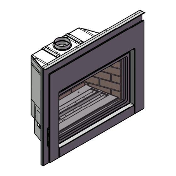
Page 3: Unit Dimensions
DIMENSIONS UNIT DIMENSIONS Diagram 1.1 Regency ® E18 Gas Fireplace Insert... -
Page 4: Table Of Contents
Step #1: Vent Connection Type A ........42 Step #1: Vent Connection Type B ........42 Step #2: Outer Shell Installation ........43 Step #3: Firebox Installation ..........43 Step #4: Surround Installation ........... 44 Regency ® E18 Gas Fireplace Insert... -
Page 5: Safety Label
SAFETY LABEL This is a copy of the label that accompanies each Regency ® Gas Insert. We have printed a copy of the contents here for your review. The safety label is located on the front inside base of the unit visible when the bottom louver is open. - Page 6 (e) A copy of all installation instructions for all Product Approved side wall horizontally vented gas fueled equipment, all venting instructions, all parts lists for venting instructions, and/or all venting design instructions shall remain with the appliance or equipment at the completion of the installation. Regency ® E18 Gas Fireplace Insert...
-
Page 7: Installation
BE DONE BY AN AUTHORIZED 9. Any safety glass removed for servicing must be replaced prior to operating the appliance. SERVICE PERSON. THE APPLIANCE The Regency ® Gas Fireplace must be installed in SHOULD BE INSPECTED BEFORE 10. To prevent injury, do not allow anyone who is accordance with these instructions. -
Page 8: Installation Checklist
fl ame does not carbon. First allow 8. Trim panels or surrounds shall not seal ventila- ® performed by an authorized Regency the unit to burn for 15-20 min. to stabilize. tion openings in the fi replace. Installer at the time of installation or service. -
Page 9: Gas Pipe Pressure Testing
fi replace that has been chosen manual shut-off valve during any pressure for the Regency ® Gas Fireplace. The gas connection is a 1/2" NPT accessible on testing of the gas supply piping system at test the left side of the unit. -
Page 10: Installation Checklist
The minimum fi replace opening for this Regency with the vent shut-off system can result 5. Determine the route for the gas supply. The valve gas insert are listed below. -
Page 11: Minimum Fireplace Clearances
17- 7/8 " covered with a non-combustible board. (454 mm). The minimum height from bottom edge of the front trim above the window to the ceiling is 37-7/8"(962 mm). Diagram 3.1 Diagram 3.2 Regency ® E18 Gas Fireplace Insert... -
Page 12: Zero Clearance Framing
6 feet of horizontal pipe with two 9 degree elbows. The venting must terminate vertically with an approved B-Vent Cap. All horizontal runs must maintain a 1/4" of rise for every foot of horizontal run. Diagram 4.2 Regency ® E18 Gas Fireplace Insert... -
Page 13: Zero Clearance Kit Installation
11. Bend ZC kit side pieces as shown and remove knockouts (if required) 7. Uninstall existing unit from framing. before installation. Bend to 90º Bend to 90º secure in place to supplied steel stud Remove knockouts (if required) Remove unit from framing Side pieces Regency ® E18 Gas Fireplace Insert... - Page 14 15. Install the back section of the ZC kit. Fasten bottom, back and side sections with (904-576) screws provided. Fasten ZC box sections with provided screws. Use 4 screws on each side to secure surround and ZC box to studs. Regency ® E18 Gas Fireplace Insert...
- Page 15 Outside fi rebox shown in position - refer to 24. Follow instructions in the E18 installation manual to complete the measurements (Step 22) before securing to surround. install of inner fi rebox. Follow Step 25 before installing faceplate. Regency ® E18 Gas Fireplace Insert...
- Page 16 INSTALLATION 25. Install lower trim piece with 2 (904-897) screws to the bottom of the ZC surround before installing faceplate. Regency ® E18 Gas Fireplace Insert...
-
Page 17: Required Steps And Procedure For The E18 Install
• Black high temp paint • Drill/ ¼” bit – Phillips bit Nibbler • Measuring tape • Level • Sharpie • Shop vacuum Optional: • Plasma cutter • Fibre drop sheet • Fire extinguisher Oscillating tool Regency ® E18 Gas Fireplace Insert... -
Page 18: Separating The Outer Firebox Shell From The Inner Firebox
Existing unit modifi cations Adaptor setting Before separating Outer Shell and Required fl ex length Unit—Clear wire harness Outer shell Leg setting / outer shell position both need to be exact as measurements indicated. Regency ® E18 Gas Fireplace Insert... - Page 19 Alternate method is to cut front bar in the center and break off each side spot weld completely. Diagram 5.4 Modidfi ed edges must be fl ush to allow proper seating of the E18 outer shell. Diagram 5.2 Grind corners Regency ® E18 Gas Fireplace Insert...
-
Page 20: Ep28-4/Ep28-5 Installation Specifi Cations
3 Install with supplied Phillips screws to pre-punched holes and tighten previous screws that were loosened in Step 1. 4. Keep left side leg loose until outer fi rebox is in position in ZC box - to allow adjustment of gas line. Regency ®... -
Page 21: Modifi Cation Of Montigo Ep28-S2
6. Remove Primary and Secondary Limit Switches (See Diagram 6.4). Diagram 6.1 4. Remove Side Filler Plates and Front Hood (See Diagram 6.2). Diagram 6.4 7. Remove Insert (See Diagram 6.5). Diagram 6.2 Diagram 6.5 Regency ® E18 Gas Fireplace Insert... - Page 22 Diagram 6.7 10. Remove the leftover ends of the front bar on the Left and Right sides so that they are fl ush with the sides of the fi rebox. (See Diagram 6.8) Diagram 6.8 Regency ® E18 Gas Fireplace Insert...
-
Page 23: Modifi Cation Of Montigo Econo Plus 28C
8. Remove 2 bolts from underneath, to remove valve, log tray, etc. 9. Lift entire assembly out. Remove 2 screws - remove Top Bracket 5. Remove Bracket and Thermodisc by removing 2 screws. Remove 2 bolts Remove 2 screws - remove Thermodisc Bracket Regency ® E18 Gas Fireplace Insert... - Page 24 14 Cut out back cross bar to complete modifi cation. Fold back any excess metal after removing the cross piece. Flatten louver brackets 12. Flatten fl ange (left ,right and rear) in locations shown below. Cut out back cross bar Flatten fl ange Regency ® E18 Gas Fireplace Insert...
- Page 25 Faceplate is centered, mark and drill 2 holes per side. The pre drilled holes should line up with the outer shell holes. Remove outer faceplate and continue with E18 installation. Install outer faceplate Regency ® E18 Gas Fireplace Insert...
- Page 26 3. Install with supplied phillips screws to prepunched holes and tighten previous screws that were loosened in Step 1. 4. Keep left side leg loose until outer fi rebox is in position in ZC box - to allow adjustment of gas line. Regency ® E18 Gas Fireplace Insert...
-
Page 27: Modifi Cation Of Montigo 28F-2 Or 28-F
4. Remove Logs and Sand from Sand Pan. 5. Remove Front Bar. (See Diagram 7.2). Diagram 7.4 8. Unscrew left and right side nuts, under the fi rebox, holding down the Sand Pan. (see Diagram 7.5) Diagram 7.2 Diagram 7.5 Regency ® E18 Gas Fireplace Insert... - Page 28 Firebox and Cut the Top of the Firebox 1” below the bot- tom of the Exhaust Collar (See Diagram 7.11 and 7.12). Diagram 7.7 11. Cut the Sides of the Top Face (See Diagram 7.8). Diagram 7.11 Diagram 7.8 Diagram 7.12 Regency ® E18 Gas Fireplace Insert...
- Page 29 15. Final Firebox Should Look Like Diagram 7.14. 14. Bend the Louver Mounts Flat. (See Diagram 7.13) Diagram 7.14 Diagram 7.13 Modifi ed edges must be fl ush to allow proper seating of the E18 outerbox. Regency ® E18 Gas Fireplace Insert...
-
Page 30: 28 F2 Installation Specifi Cations
3. Install with supplied phillips screws to prepunched holes and tighten previous screws that were loos- ened in Step 1. 4. Keep left side leg loose until outer fi rebox is in position in ZC box - to allow adjustment of gas line. Regency ® E18 Gas Fireplace Insert... -
Page 31: Modifi Cation Of Montigo 36Sr
4. Remove Logs and Sand from Sand Pan. 5. Remove Top Rail securing the Bifold Doors (See Diagram 8.2). Diagram 8.4 8. Unscrew and Remove Trim Around Sand Pan (See Diagram 8.5). Diagram 8.2 Diagram 8.5 Regency ® E18 Gas Fireplace Insert... - Page 32 Top Left and right corner screws back in (See Diagram 8.9 and 12. Unscrew Left and Right Nuts Underneath the Firebox Holding 8.10). Down the Sand Pan. (See Diagram 8.7) 13. Remove Sand Pan and Pilot Assembly. Diagram 8.9 Diagram 8.7 Diagram 8.10 Regency ® E18 Gas Fireplace Insert...
- Page 33 16. Remove Louver Supports in all 4 corners of the Appliance (See 17. Final fi rebox should look like Diagram 8.12. Diagram 8.11). Diagram 8.12 Diagram 8.11 Modifi ed edges must be fl ush to allow proper seating of the E18 outerbox. Regency ® E18 Gas Fireplace Insert...
- Page 34 3. Install with supplied phillips screws to prepunched holes and tighten previous screws that were loosened in Step 1. 4. Keep left side leg loose until outer fi rebox is in position in ZC box - to allow adjustment of gas line. Regency ®...
-
Page 35: Modifi Cation Of Firesong 220N
6. Bend the Inner Rear Baffl e up so it is fl ush with the back of the Firebox or cut off the Baffl e if it will not bend fl at with the back of the Firebox. Diagram 9.2 Regency ® E18 Gas Fireplace Insert... - Page 36 7. Cut The Top Front Flange of the Firebox (See Diagram 9.5). should look like Diagram 9.6. Diagram 9.5 Diagram 9.6 Modifi ed edges must be fl ush to allow proper seating of the E18 outerbox. Regency ® E18 Gas Fireplace Insert...
- Page 37 3. Install with supplied phillips screws to prepunched holes and tighten previ- ous screws that were loosened in Step 1. 4. Keep left side leg loose until outer fi rebox is in position in ZC box - to allow adjustment of gas line. Regency ® E18 Gas Fireplace Insert...
-
Page 38: Modifi Cation Of Firesong 120N
(See Diagram 1.6). Diagram 1.2 4. Remove Top Rail securing Mesh. (See Diagram 1.3). Diagram 1.6 9. Remove Valve. 10. Make 2 vertical cuts on Top Facing. (See Diagram 1.7). Diagram 1.3 Diagram 1.7 Regency ® E18 Gas Fireplace Insert... - Page 39 Cut off bar at back of fi rebox. Diagram 1.11 Back bar Diagram 1.9 13. Remove 6 screws, one at a time, and replace with pan head (wafer screws) - in locations shown below. Diagram 1.12 Diagram 1.10 Diagram 1.13 Regency ® E18 Gas Fireplace Insert...
- Page 40 16. Repeat Steps 14 & 15 on left side. 17. Remove existing Firesong rating plate from cut out fi rebox. This rating plate must be retained and affi xed to the unit. (See Diagram 1.14 and 1.15). Diagram 1.14 Regency ® E18 Gas Fireplace Insert...
- Page 41 3 Install with supplied Phillips screws to pre-punched holes and tighten previous screws that were loosened in Step 1. 4. Keep left side leg loose until outer fi rebox is in position in ZC box - to allow adjustment of gas line. See Step #2: Outer Shell installation for procedure. Regency ® E18 Gas Fireplace Insert...
-
Page 42: Installation Of The E18 Into Existing Units
Slide Plate assembly to the fi rebox top of the existing fi rebox. Two (2) screws go through the Vent Slide Plate and Adaptor Plate, two (2) screws go through the Adaptor Plate only. Diagram 10.2 Regency ® E18 Gas Fireplace Insert... -
Page 43: Step #2: Outer Shell Installation
Measured from side of Top of ZC box ZC box EP28 8-7/16" (215mm) 1-7/16" (37mm) 28F - 28F2 7-3/16" (183mm) 1-1/2" (39mm) Montigo 36SR 6-3/8" (162mm) 1-9/16" (40mm) Firesong 220N 8-3/16" (208mm) 2-1/8" (54mm) Regency ® E18 Gas Fireplace Insert... -
Page 44: Step #4: Surround Installation
11. Install control cover, adjust horizontal alignment by sliding mounting control cover to ensure even spacing on both sides. Ensure bracket control cover is seated down all the way. Diagram 10.10 DRAFT RELIEF OPENINGS MUST NOT BE COVERED OR BLOCKED. Diagram 10.7 Regency ® E18 Gas Fireplace Insert... -
Page 45: Remote Control Installation
6b. GT remote control: Attach the white wire from the wiring harness labeled TP/TH and connect it to the red wire disconnected in the previous steps, see Diagram 6. Receiver Diagram 2—Receiver in position Diagram 6 Regency ® E18 Gas Fireplace Insert... - Page 46 (grounding) plug for your protection against shock hazard and should be plugged directly into a prop- erly grounded three-prong receptacle. Do not cut or remove the grounding prong from this plug. ON/OFF switch wires Diagram 9 Regency ® E18 Gas Fireplace Insert...
- Page 47 22. Check operation of fl ame control. knob (Fig.1). 23. Adjust the burner aeration setting to Fully Open and adjust as required for the best fl ame picture. Fig.5 24. See manual for Gas Pressure Testing instruc- tions. Fig. 1 Regency ® E18 Gas Fireplace Insert...
-
Page 48: Glass Burner Installation
Diagram 11.1 2. Make sure to feed the Air Shutter Bar through the lower hole in the valve tray, just above the ignitor as you place the Glass Burner in. Diagram 11.4 Diagram 11.2 Regency ® E18 Gas Fireplace Insert... -
Page 49: Enamel Panel Installation
1. Centre back panel on the back wall of the fi rebox. with one screw (provided). Panel Clip 2. Slide in side panel into place in lower track. 4. Repeat steps 2 & 3 on other side. Final Install Regency ® E18 Gas Fireplace Insert... -
Page 50: Glass Crystal And Stone Install
NOTE: Correct fi nal glass installation of Crystals shown in step 3 and 4. The Burner and Firebox Floor should not be visible when the fl ame is out. OPTIONAL SPA OR VOLCANICSTONES INSTALLATION (AROUND BURNER) Diagram 12.7 Diagram 12.8 NOTE: Spa or Volcanic Stones are NOT to be placed anywhere on the burner tube or Pilot assembly area. Regency ® E18 Gas Fireplace Insert... -
Page 51: Brick Panel Installation
3. Positon panel so that grout line in the panel lines up with screw in the baffl e. 4. If required, lower screw to secure panel in position. Line up screw and grout line. Regency ® E18 Gas Fireplace Insert... -
Page 52: Log Tray Installation
3. Install the Log Burner the same way as the Glass Burner (see installation manual for instructions). 4. Fill the Log Burner with 2lbs of black glass crystals. 2. Place Log B at the front left of the Log Tray. Regency ® E18 Gas Fireplace Insert... - Page 53 Ember Lava, Embaglow, Platinum Embers 5. Place Log D on the left pin of Log A and the groove in Log B. Final Install Regency ® E18 Gas Fireplace Insert...
-
Page 54: Optional Log Set Installation
5. Install log brackets by clipping brackets to back of burner tray - measure 4" from outside edge of the burner tray to outside edge of bracket. 4" 4-1/2" Log 2 in position Brackets installed 4" from outside edge of burner tray Regency ® E18 Gas Fireplace Insert... - Page 55 11. Installed Log 3 should touch burner position in the location shown below. * Measurement taken from left edge of burner tray - approximately 18". E18 fi nal install 18" Installed position of Log 3 Regency ® E18 Gas Fireplace Insert...
-
Page 56: Glass Door Installation
1. Remove Door as per E18 Installation section of the manual. 2. Remove the 4 screws to remove Safety Screen from Door. 3. Reverse order to reattach. 4. Install control cover supplied with screen. Diagram 13.3 Regency ® E18 Gas Fireplace Insert... -
Page 57: Drafthood Check
Make sure the Glass Door is on properly. and install into the receptacle box. Use the Regency Remote Control Kit approved for this unit. Use of other systems may void your 2. Light the unit and set controls to maximum. -
Page 58: Safety Switches
Use cord channel to obscure cord and keep tidy. The cord is located on the left hand side of the appliance. 1. Open channel and feed cord through. 2. Peel off backing of cord channel and adhere to hearth. Diagram 15.1 Regency ® E18 Gas Fireplace Insert... -
Page 59: Final Check
"OFF". Do not force. 4. Pilot must be shut off during prolonged non use periods to conserve fuel. 4. Disconnect all electric power and gas to the appliance if service is to be performed. Regency ® E18 Gas Fireplace Insert... -
Page 60: Copy Of Lighting Plate Instructions
3) Turn off all electric power to the appliance if service is to be performed. Pilot must be shut off during prolonged non use periods 918-475 to conserve fuel. DO NOT REMOVE THIS INSTRUCTION PLATE Regency ® E18 Gas Fireplace Insert... -
Page 61: Operation
This is perfectly normal due to must use the proper replacement log. The position ant paint (not with wall paint). Regency ® uses the fact that there are various gauges and types of these logs must be as shown in the diagram StoveBrite Paint - Metallic Black #6309. -
Page 62: Valve Replacement
8. Unscrew the 8 screws holding down the Valve Tray. Diagram 17.2 9. Slide the Valve Tray out about half way giving easier access to the gas connection at the valve. Diagram 17.3 10. Disconect the gas line and remove the valve tray. Regency ® E18 Gas Fireplace Insert... -
Page 63: Removing The Fan
8. Loosen 4 screws holding in Air Inlet Baffl e and remove it. 9. Loosen 3 screws holding in the Circulation Fan. 10. Disconnect Power Leads on Fan Motor Diagram 18.2 11. Reverse Steps to reinstall. Regency ® E18 Gas Fireplace Insert... -
Page 64: Wiring Diagrams
(grounding) plug for your protection against shock cause improper and dangerous hazard and should be plugged directly into a prop- operation. erly grounded three-prong receptacle. Do not cut or remove the grounding prong from this plug. Regency ® E18 Gas Fireplace Insert... -
Page 65: Parts List
Orifi ce Mount 616-929 Mesh screen 910-190 Piezo Ignitor 616-040 Glass door 904-946 Gas Orifi ce 616-048 Surround Bracket L 910-034 Pilot Assembly 911-119 Spill Switch 616-526 Burner W241050 Fan Switch 910-568 Gas Valve Regency ® E18 Gas Fireplace Insert... -
Page 66: Montigo Ep28 Installation Kit
616-068 Surround Panel Rear 616-067 Surround Front 904-960 Ring clamp -Installer supplied Magnet and Bracket 948-338 Flex Vent Section - Installer supplied 10 616-051 Control Cover 616-023 Flue Slider Plate Upper Trim/ heat shield Regency ® E18 Gas Fireplace Insert... -
Page 67: Montigo Econo Plus 28C Installation Kit
Faceplate Hanger Right 904-960 Ring clamp -Installer supplied 904-057 Magnet and Bracket 948-338 Flex Vent Section - Installer supplied 12 616-051 Control Cover 616-023 Flue Slider Plate 616-053 Upper Trim/ heat shield - remove and discard Regency ® E18 Gas Fireplace Insert... -
Page 68: Montigo 28-F And 28F-2 Installation Kit
Diagram 22.1 Part # Description Part # Description 616-070 Adaptor plate gasket E18 Body 616-069 Adaptor plate 616-068 Surround Panel Rear 616-067 Surround Panel Right 904-960 Ring clamp -Installer supplied Magnet and Bracket 948-338 Flex Vent Section - Installer supplied 11 616-051 Control Cover 616-023... -
Page 69: Montigo 36Sr Installation Kit
PARTS LIST Diagram 23.1 Regency ® E18 Gas Fireplace Insert... -
Page 70: Firesong 220N Installation Kit
PARTS LIST Diagram 24.1 Regency ® E18 Gas Fireplace Insert... -
Page 71: Firesong 120N Installation Kit
Firesong 120N Installation Kit Item Part # Description Item Part # Description Faceplate panel Front Ring Clamp Magnet Bracket (not shown) Flex section Control Cover Adaptor Slide Plate Firesong 120N Firebox supports E18 Chassis Faceplate panel Rear Regency ® E18 Gas Fireplace Insert... - Page 72 NOTES Regency ® E18 Gas Fireplace Insert...
- Page 73 NOTES Regency ® E18 Gas Fireplace Insert...
- Page 74 NOTES Regency ® E18 Gas Fireplace Insert...
-
Page 75: Warranty
It is the general practice of FPI to charge for larger, higher priced replacement parts and issue credit once the replaced component has been returned to FPI and evaluated for manufacturer defect. The authorized selling dealer is responsible for all in-fi eld service work carried out on your Regency product. FPI will not be liable for results or costs of workmanship from unauthorized service persons or dealers. - Page 76 Dealer Name & Address: ______________________________________________ ___________________________________________________________________ Installer: ___________________________________________________________ Phone #: ___________________________________________________________ Date Installed: ______________________________________________________ Serial No.: __________________________________________________________ Regency and Energy are trademarks of FPI Fireplace Products International Ltd. Printed in Canada © Copyright 2014, FPI Fireplace Products International Ltd. All rights reserved.
Need help?
Do you have a question about the E18-NG and is the answer not in the manual?
Questions and answers