Table of Contents
Advertisement
Quick Links
WARNING
FIRE OR EXPLOSION HAZARD
Failure to follow safety warnings exactly could result in serious
injury, death, or property damage.
- Do not store or use gasoline or other flammable vapors and liquids in the vicinity of this or any other
appliance.
- WHAT TO DO IF YOU SMELL GAS
•
Do not try to light any appliance.
• Do not touch any electrical switch: do not use any phone in your building.
Leave the building immediately.
• Immediately call your gas supplier from a neighbour's phone. Follow the gas supplier's
instructions.
• If you cannot reach you gas supplier, call the fire department.
- Installation and service must be performed by a qualified installer, service agency or the gas supplier.
Tested by:
919-379a
REGENCY FIREPLACE PRODUCTS INTERNATIONAL LTD. 6988 Venture St., Delta, BC, Canada V4G 1H4
Energy
MODELS:
E33-NG10 Natural Gas
Owners & Installation Manual
Installer: Please complete the details on the back cover
and leave this manual with the homeowner.
Homeowner: Please keep these instructions for future reference.
E33 Gas Insert
™
E33-LP10 Propane
09.17.15
Advertisement
Table of Contents

Related Manuals for Regency Energy E33-NG10


Summary of Contents for Regency Energy E33-NG10
- Page 1 Tested by: Installer: Please complete the details on the back cover and leave this manual with the homeowner. Homeowner: Please keep these instructions for future reference. 919-379a REGENCY FIREPLACE PRODUCTS INTERNATIONAL LTD. 6988 Venture St., Delta, BC, Canada V4G 1H4 09.17.15...
- Page 2 REGENCY GAS FIREPLACE INSERT TO THE NEW OWNER Congratulations! You are the owner of a state-of-the-art Gas Insert by Regency. The E33 Gas Insert has been designed to provide you with all the warmth and charm of a fireplace, at the flick of a switch.
-
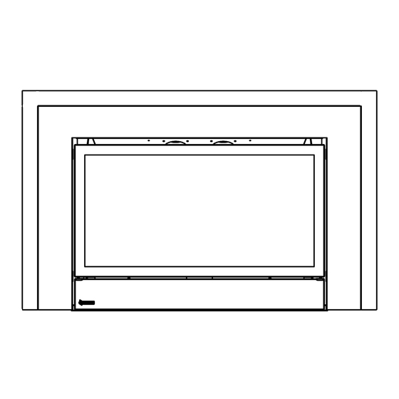
Page 3: Unit Dimensions Low Profile Faceplate
dimensions UNIT DIMENSIONS LOW PROFILE FACEPLATE 32-1/4 819mm 24-1/2 (622mm) " (83mm) 2 " " (1181mm) (44mm) 16 " (1078mm) (281mm) 4 " (413mm) E33-10 FPI Direct Vent Gas Insert... -
Page 4: Unit Dimensions Optional Vignette Faceplate With Spacer
dimensions UNIT DIMENSIONS OPTIONAL VIGNETTE FACEPLATE WITH SPACER VIGNETTE STANDARD WITH SPACER E33-10 FPI Direct Vent Gas Insert... -
Page 5: Dimensions
dimensions UNIT DIMENSIONS OPTIONAL VIGNETTE FACEPLATE WITHOUT SPACER VIGNETTE STANDARD- NO SPACER E33-10 FPI Direct Vent Gas Insert... -
Page 6: Unit Dimensions Oversize Backingplate With Spacer
dimensions UNIT DIMENSIONS OVERSIZE BACKINGPLATE WITH SPACER E33-10 FPI Direct Vent Gas Insert... -
Page 7: Unit Dimensions Optional 4 Sided Vignette Faceplate
dimensions UNIT DIMENSIONS OPTIONAL 4 SIDED VIGNETTE FACEPLATE 4 SIDED VIGNETTE FACEPLATE E33-10 FPI Direct Vent Gas Insert... -
Page 8: Table Of Contents
table of contents DIMENSIONS For E33-10 Using Sit 829 Nova Gas Valve ....21 Optional Vignette Faceplate Installation ......22 Spacer Installation For 3 Sided Vignette Faceplate ..23 Unit Dimensions Low Profile Faceplate ......3 Oversize Backing Plate Installation ......24 Unit Dimensions Optional Vignette Faceplate Optional Vignette Inlay Installation ......25 With Spacer ..............4 Optional Hearth Trim Installation- Vignette Faceplate... -
Page 9: Safety Decal
Ensure that the safety label is attached to the unit. NOTE: Regency units are constantly being improved. Check the label on the unit and if there is a difference, the label on the unit is the correct one. -
Page 10: Requirements
requirements MA Code - CO Detector (for the State of Massachusetts only) 5.08: Modifications to NFPA-54, Chapter 10 (2) Revise 10.8.3 by adding the following additional requirements: (a) For all side wall horizontally vented gas fueled equipment installed in every dwelling, building or structure used in whole or in part for residential purposes, including those owned or operated by the Commonwealth and where the side wall exhaust vent termination is less than seven (7) feet above finished grade in the area of the venting, including but not limited to decks and porches, the following requirements shall be satisfied:... -
Page 11: Installation
2) Installation and repair should be done by a CIALLY THE FIREPLACE GLASS, AND qualified service person. SHOULD STAY AWAY TO AVOID BURNS The Regency Gas Insert must be installed in OR CLOTHING IGNITION. 3) The appliance should be inspected before use accordance with these instructions. Carefully read and at least annually by a professional service all the instructions in this manual first. -
Page 12: Gas Pressure Testing
Approved as is for use at 0' to 4,500' Adjusting the primary air, if required, to (0-1370m). The Regency Gas Insert is installed as listed below. ensure that the flame does not carbon. Electrical: 120V A.C. system. -
Page 13: Gas Insert Aeration System
MINIMUM FIREPLACE OPENING GAS INSERT AERATION SYSTEM The minimum fireplace opening for the Regency gas fireplace insert is shown in the following diagram and the table: The air shutter can be adjusted by moving the adjusting wire up or down. The wire is accessed through the bottom louver opening. -
Page 14: Combustible Mantel Clearances
installation MINIMUM CLEARANCES TO COMBUSTIBLES From Unit Side Walls * A 8" (203 mm) Ceiling B 47" (1194 mm) Min. Mantel Height C 15" (381 mm) Max. Mantel Depth D 12" (305 mm) Alcove Width E 76" (1930 mm) Alcove Depth 36"... -
Page 15: Gas Connection
Part # Description 948-305 3" Flex - 35 ft. 946-529 Regency Co-linear DV Vertical Termination Cap Alternate Approved Caps 46dva-VC Vertical Termination Cap 46dva-VCH High Wind Cap 46dva-GK 3" Co-linear Adaptor with flashing... -
Page 16: Remote Receiver Installation
installation REMOTE RECEIVER INSTALLATION DC SPARK IGNITER BATTERY 1) Install the heat shield to the receiver with two screws. INSTALLATION Install the supplied battery into the DC Sparker Box by opening the battery compartment. NOTE: The battery in the DC Sparker Box will need to be replaced annually. -
Page 17: Brick Panel Installation
installation BRICK PANEL INSTALLATION 6) Slide the top panel and bracket assembly 9) Insert the side panel by positioning it flat carefully onto the baffle plate ensuring the against the side walls. Tilt the panel panel is centered. Make sure the tabs of the towards the middle of the firebox, then insert 1) Remove safety screen and glass door if top bracket fit into the baffle openings (refer to... -
Page 18: Log Set Installation
DIRECT VENT FIREPLACE installation LOG SET INSTALLATION LOG INSTALLATION WARNING: 3) Remove the grate by removing the two Phillips Dangerous operating conditions may occur if these screws. Slide the grate outwards to remove it from logs are not positioned in their correct certifi ed loca- the unit (refer to Diagram 1). - Page 19 DIRECT VENT FIREPLACE installation 7) Align the bottom grooves of log 03-21 onto the right side of the grate and gently slide the log back until it touches the locating tab (refer to Diagram 4 & 5). 03-23 03-21 03-21 03-17 Locating Diagram 7...
- Page 20 DIRECT VENT FIREPLACE installation 12) Place log 03-19 over the left center of the grate. Ensure the log set looks like Diagram 12. 03-23 03-18 03-22 03-20 03-17 Diagram 10 03-19 Diagram 12 11) Place log 03-24 over log 03-23 and log 03-21 ensuring the pin hole of log 03-24 lines up with the right pin of log 03-23 and the right pin of log 03-21 13) Separate platinum embers and place at the front...
-
Page 21: Conversion Kit 342-969 From Ng To Lp
E33-10 installation Conversion from NG to LP CONVERSION KIT 342-969 FROM NG TO LP for E33-10 using SIT 829 NOVA Gas Valve for E33-10 using SIT 829 NOVA Gas Valve THIS CONVERSION MUST BE DONE BY A QUALIFIED GAS FITTER IF IN DOUBT DO NOT DO THIS CONVERSION !! THIS CONVERSION MUST BE DONE BY A QUALIFIED GAS FITTER IF IN DOUBT DO NOT DO THIS CONVERSION !! 7. Unscrew the pilot orifice with the 5/32"... -
Page 22: Optional Vignette Faceplate Installation
installation E33-10 OPTIONAL VIGNETTE FACEPLATE INSTALLATION OPTIONAL VIGNETTE FACEPLATE INSTALLATION 1. Install the lower trim to the unit with 2 screws on each side as shown in the drawing below. 4. Tuck the wires into the silver box and secure them with a small grommet. -
Page 23: Spacer Installation For 3 Sided Vignette Faceplate
installation E33-10 SPACER INSTALLATION FOR 3 SIDED VIGNETTE FACEPLATE SPACER INSTALLATION FOR 3 SIDED VIGNETTE FACEPLATE 3. Finally, attach the spacer to vignette faceplate (vignette NOTE: faceplate is purchased seperately) with 2 side screws on • A spacer can be ordered, if required. the top (1 per side). -
Page 24: Oversize Backingplate Installation
installation E33-10 OVERSIZE BACKING PLATE INSTALLATION OVERSIZE BACKINGPLATE INSTALLATION OVERSIZE BACKING PLATE INSTALLATION OVERSIZE BACKING PLATE INSTALLATION WITH WITHOUT SPACER SPACER Oversize backing plate can be ordered for the unit 1) Install the spacer to the back of the faceplate backing with 6 if required. -
Page 25: Optional Vignette Inlay Installation
installation E33-10 OPTIONAL VIGNETTE INLAY INSTALLATION OPTIONAL VIGNETTE INLAY INSTALLATION 1. Remove 5 screws from the backside of the Vignette frame cover 2. Take the mesh screen out of the Vignette front frame as shown and keep them aside (3 at bottom and 2 at top). below. - Page 26 installation E33-10 6. Reverse step1. 5. With the Inlay in position, place the mesh screen over the inlay. NOTE: The flush side of the mesh screen should face the inlay. 7. Install the Vignette frame with Inlay onto the 2 hooks provided on the unit.
-
Page 27: Optional Hearth Trim Installation- Vignette Faceplate With Spacer And Low Profile Faceplate
installation LRI4E/HRI4E/LRI6E/HRI6E/E33 OPTIONAL HEARTH TRIM INSTALLATION- VIGNETTE FACEPLATE WITH SPACER AND LOW OPTIONAL HEARTH TRIM INSTALLATION -VIGNETTE FACEPLATE WITH SPACER PROFILE FACEPLATE AND LOW PROFILE FACEPLATE 5) Secure the hearth trim with a clip on its side to keep it steady as shown in Customizing the Hearth Trim: the picture below . -
Page 28: Optional Hearth Trim Installation- Vignette Faceplate Without Spacer
LRI4E/HRI4E/LRI6E/HRI6E/E33 installation OPTIONAL HEARTH TRIM OPTIONAL HEARTH TRIM INSTALLATION- VIGNETTE FACEPLATE WITHOUT SPACER INSTALLATION - VIGNETTE FACEPLATE WITHOUT SPACER Customizing the Hearth Trim The Hearth Trim can be adjusted to custom fit an installation by pulling apart the top piece from the bottom piece. Minimum height of the hearth trim is 2”... -
Page 29: Optional Hearth Trim Installation-Low Profile
installation E33-10 OPTIONAL HEARTH TRIM INSTALLATION- LOW PROFILE OPTIONAL HEARTH TRIM INSTALLATION- LOW PROFILE If you do not have spacer, remove the spacer brackets from the heart trim by removing 3 screws per side. Refer to diagrams 1 and 2 below. Diagram 1-Top View Spacer Brackets Front... -
Page 30: Safety Screen Installation- Low Profile Faceplate
installation SAFETY SCREEN INSTALLATION- LOW PROFILE FACEPLATE 1. To remove safety screen, flip open bottom louver and remove 2 screws 2. Pull off safety screen and frame from glass door. in locations shown below. 3. To install, reverse Steps 2-1. STANDARD FLUSH DOOR NOTE: See Vignette or Low Profile Faceplate instructions for removal... -
Page 31: Wiring Diagram
20 Ft. wall thermostat wires installed on an interior wall. to 120V wire. 20 GA. 12 Ft. Regency offers an optional programmable ® 22 GA. 9 Ft. thermostat but any 250-750 millivolt rated non- anticipator type thermostat that is CSA, ULC or NOTE: When the wall thermostat is connected, the remote control transmitter UL approved may be used. -
Page 32: Operating Instructions
operating instructions FIRST FIRE 8) The unit should never be turned off, and on again without a minimum of a 60 second wait. 5. Press and release the ON/OFF button on the remote handheld transmitter. An audible beep The first fire in your stove is part of the paint curing 9) Hook up remote receiver to wire marked 'receiver' should be heard from the receiver. -
Page 33: Copy Of Lighting Instruction Plate
Blower: QUE FAIRE SI VOUS SENTEZ UNE ODEUR DE GAZ : Regency gas appliances use high tech blowers • Ne pas tenter d’allumer d’appareil to push heated air farther into the room. It is not •... -
Page 34: Maintenance
(not with wall paint). service technician to inspect the appliance 3) Check for evidences of excessive Regency uses StoveBrite Paint - Metallic and to replace nay part of the control system condensation, such as water droplets forming Black #6309. -
Page 35: Door Glass
To Remove Fan: the 2 screws. 1) Turn the unit off and allow it to cool down to Your Regency stove is supplied with high room temperature. temperature, 5 mm Neoceram ceramic glass that will withstand the highest heat that your unit will Screws 2) Unplug or disconnect power source to stove. -
Page 36: Valve Assembly Removal And Installation
maintenance 11) Disconnect the inlet gas line. 13) Pull Fan Assembly forward, to disengage 7) Remove base brick set. (When removing the fan clip on the rear wall. Then lift the base brick sides the two screws that hold Fan Assembly up and pull through firebox the grate down must be removed first). -
Page 37: Parts List
parts list MAIN ASSEMBLY Part # Description 1) 340-038 Fan Access Plate 2) 340-103 Gasket - Fan Access Plate 3) 320-517/P Fan Assembly 120 V 910-331/P Fan Motor 120 V 5) 910-750 Power Cord 910-752 Wire Harness (Faceplate) 7) 910-142 Fan Auto On/Off Thermodisc 8) * Thermodisc Bracket... -
Page 38: Burner & Log Assembly
parts list BURNER & LOG ASSEMBLY Part # Description 52) 340-104 Gasket - Valve Tray 342-574/P Valve Assembly - NG 342-576/P Valve Assembly - LP 57) 910-578 Valve - S.I.T. - Natural Gas 910-580 Valve - S.I.T. - Propane 59) * Valve Tray 66) 910-038 Pilot Assy-3 Flame-S.I.T.-NG... -
Page 39: Vignette Faceplate
parts list VIGNETTE FACEPLATE Part # Description 342-957 Oversize Backing Plate 342-924 Faceplate Low Profile Mt. Black 342-954 Backing Plate Custom 3-Sided 342-934 Faceplate Vignette 4 sided.Mt. Black 342-914 Faceplate Vignette Mt. Black Vignette 342-934 Faceplate Vignette 4 sided Mt. Black 342-959 Backing Plate Custom 4 Sided 342-958... - Page 40 notes 40 | E33-10 FPI Direct Vent Gas Insert...
- Page 41 notes E33-10 FPI Direct Vent Gas Insert...
- Page 42 notes 42 | E33-10 FPI Direct Vent Gas Insert...
-
Page 43: Warranty
Conditions: Any part or parts of this unit which in our judgement show evidence of such defects will be repaired or replaced at Regency's option, through an accredited distributor or agent provid- ed that the defective part be returned to the distributor or agent Transportation Prepaid, if requested. - Page 44 Installer: Please complete the following information Dealer Name & Address: ______________________________________________ ___________________________________________________________________ Installer: ___________________________________________________________ Phone #: ___________________________________________________________ Date Installed: ______________________________________________________ Serial No.: __________________________________________________________ Regency and Energy are trademarkds of Fireplace Products International Ltd. © Copyright 2015,Fireplace Products International Ltd. All rights reserved. Printed in Canada...
Need help?
Do you have a question about the Energy E33-NG10 and is the answer not in the manual?
Questions and answers