Table of Contents
Advertisement
Quick Links
Download this manual
See also:
Installation Manual
Advertisement
Table of Contents

Related Manuals for Panasonic WJ-GXE100


Summary of Contents for Panasonic WJ-GXE100
-
Page 1: Operating Instructions
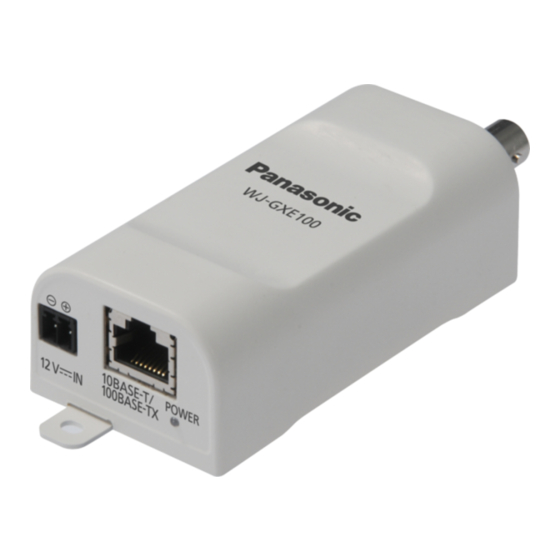
Operating Instructions Network Video Encoder WJ-GXE100 Model No. WJ-GXE100E Before attempting to connect or operate this product, please read these instructions carefully and save this manual for future use. The model number is abbreviated in some descriptions in this manual. - Page 2 Preface Preface About the user manuals There are 2 sets of operating instructions for the WJ-GXE100 (P model), WJ-GXE100E (E model) as follows. • Installation Guide: Explains how to install and connect devices. • Operating Instructions: Explains how to perform the settings and how to operate this unit.
- Page 3 Preface Viewer software It is necessary to install the viewer software “Network Camera View 4S” (ActiveX ) to display images on a PC. ® This software can be installed directly from the unit or by selecting the [Install] button next to [Viewer Software] on the menu of the CD-ROM provided, and then following the on-screen instructions.
-
Page 4: Table Of Contents
Set the VMD areas [VMD area] ..................50 10.4 Configuration of the settings relating to the E-mail notification [Notification] ..52 10.5 Configure the settings relating to Panasonic alarm protocol [Notification] .....53 11 Configure the settings relating to the authentication [User mng.] .......................56 11.1 Configure the settings relating to the user authentication [User auth.] ....56... - Page 5 Installing Panasonic “IP Setting Software” ..............114 18.3 Installing the manuals ....................115 18.4 Installing the Viewer software ..................115 18.5 Configure the network settings of the unit using the Panasonic “IP Setting Software” ........................116 19 About the displayed system log ............118 Operating Instructions...
- Page 6 Table of Contents 20 Troubleshooting ...................122 Operating Instructions...
-
Page 7: Monitor Images On A Pc
The following are descriptions of how to monitor images from the camera on a PC. 1.1 Monitor images from a single camera Start up the web browser. Enter the IP address designated using the Panasonic “IP Setting Software” in the address box of the browser. •... - Page 8 1 Monitor images on a PC Press the [Enter] key on the keyboard. → The “Live” page will be displayed. Refer to page 9 for further information about the “Live” page. When “On” is selected for “User auth.”, the authentication window will be displayed before displaying live images for the user name and password entries.
-
Page 9: About The "Live" Page
1 Monitor images on a PC 1.2 About the “Live” page [select language] pull-down-menu The unit’s display language can be selected. The default language can be set in the [Language] in the [Basic] settings. (®page 27) [Setup] button Displays the setup menu. The button will turn green and the setup menu will be displayed. [Live] button Displays the “Live”... - Page 10 1 Monitor images on a PC [Image capture size] buttons These buttons will be displayed only when a JPEG image is displayed. [VGA] The characters “VGA” will turn green and images in the main area will be displayed in VGA size. [QVGA] The characters “QVGA”...
- Page 11 1 Monitor images on a PC • While a camera controlled via RS485 communication is executing a patrol function, it is impossible to start another one. Stop the current patrol function before starting a new one. • To activate auto pan, sort, preset position sequence or patrol 1-4, it is required to perform the settings on the setup menu of camera in advance.
- Page 12 1 Monitor images on a PC *A phenomenon in which portions of the screen are displayed out of alignment. Only operable by users whose access level is “1. Administrator”. Only operable by users whose access level is “1. Administrator” or “2. Camera control” when “On” is selected for “User auth.” (®page 56) Operating Instructions...
-
Page 13: Monitor Images From Multiple Cameras
• When displaying images on a 4-screen, panning, tilting and zooming operations become available only for images from cameras with Pan/Tilt/Zoom functions. Refer to our website (http://panasonic.net/pss/security/support/info.html) for further information about the compatible cameras and their versions. • Only JPEG images can be displayed on a multi-screen. -
Page 14: Monitor Images On A Cellular Phone/Mobile Terminal
2 Monitor images on a cellular phone/mobile terminal 2 Monitor images on a cellular phone/mobile terminal 2.1 Monitor images on a cellular phone It is possible to connect to the unit using a cellular phone via the Internet and monitor images (JPEG only) from the unit on the screen of the cellular phone. -
Page 15: Monitor Images On A Mobile Terminal
When an Android terminal is used, an MJPEG format image is displayed by the Firefox browser, but a JPEG ® format image is displayed by the standard browser. For further information about compatible devices, refer to our website (http://panasonic.net/pss/security/support/info.html). Operating Instructions... - Page 16 2 Monitor images on a cellular phone/mobile terminal IMPORTANT • When the authentication window is displayed, enter the user name and password. The default user name and password are as follows. User name: admin Password: 12345 To enhance the security, change the password for the user “admin”. (®page 56) Note •...
- Page 17 2 Monitor images on a cellular phone/mobile terminal • When the resolution is changed by the resolution control, the displayed resolution changes but the image size remains the same. • When the HTTP port number is changed from “80”, enter “http://IP address: (colon) + port number/ cam”...
-
Page 18: Action At An Alarm Occurrence
When “On” is selected for “Panasonic alarm protocol notification”, the connected Panasonic device will be notified that the unit is in the alarm state. The settings for Panasonic alarm protocol can be configured in the Panasonic alarm protocol section of the [Notification] tab of the [Alarm] page. (®page 53) -
Page 19: Transmit Images Onto An Ftp Server
4 Transmit images onto an FTP server 4 Transmit images onto an FTP server Images can be transmitted to an FTP server. By configuring the following settings, transmission of images captured at an alarm occurrence or captured at a designated interval to an FTP server will become available. IMPORTANT •... -
Page 20: About The Network Security
5 About the network security 5 About the network security 5.1 Equipped security functions The following security functions are featured in this unit. Access restrictions by the host authentication and the user authentication It is possible to restrict users from accessing the unit by setting the host authentication and/or the user authentication to “On”. -
Page 21: Display The Setup Menu From A Pc
6 Display the setup menu from a PC 6 Display the setup menu from a PC The settings of the unit can be configured on the setup menu. IMPORTANT • The setup menu is only operable by users whose access level is “1. Administrator”. Refer to page 56 for how to configure the access level. - Page 22 6 Display the setup menu from a PC → The setup menu will be displayed. Refer to page 25 for further information about this menu. Operating Instructions...
-
Page 23: How To Operate The Setup Menu
6 Display the setup menu from a PC 6.2 How to operate the setup menu Menu buttons Setup page Click the desired button in the frame on the left of the window to display the respective setup menu. When there are tabs at the top of the “Setup” page displayed in the frame on the right of the window, click the desired tab to display and configure the setting items relating to the name of the tab. - Page 24 6 Display the setup menu from a PC <Example> When completing the setting items in field A, click the [Set] button (B) below field (A). The edited settings in field A will not be applied unless the [Set] button (B) below field (A) is clicked. In the same manner as above, click the [Set] button (D and F) below field C and E when completing the setting items in field C and E.
-
Page 25: About The Setup Menu Window
6 Display the setup menu from a PC 6.3 About the setup menu window [Setup] button Displays the “Setup” page. [Live] button Displays the “Live” page. [Basic] button Displays the “Basic” page. The basic settings such as time and date and the unit title, and the settings required to connect the unit to the Internet can be configured on the “Basic”... - Page 26 6 Display the setup menu from a PC [Network] button Displays the “Network” page. The network settings and the settings relating to DDNS (Dynamic DNS), SNMP (Simple Network Management Protocol) and the FTP (File Transfer Protocol) periodic transmission can be configured on the “Network” page. (®page 66) [Schedule] button Displays the “Schedule”...
-
Page 27: Configure The Basic Settings Of The Unit [Basic]
Enter the title of the unit. Click the [Set] button after entering the title of the unit. The entered title will be displayed in the unit title field. • Available number of characters: 0 - 20 characters • Unavailable characters: " & • Default: WJ-GXE100 Operating Instructions... - Page 28 7 Configure the basic settings of the unit [Basic] [Date/time] Enter the current time and date. When “12h” is selected for “Time display format”, “AM” or “PM” can be selected. • Available range: Jan/01/2010 00:00:00 - Dec/31/2035 23:59:59 IMPORTANT • Use an NTP server when the more accurate time &...
- Page 29 7 Configure the basic settings of the unit [Basic] • Default: None (blank) [OSD] - [Position] Select the position where the time and date and a character string to be displayed on the image of the “Live” page. • Upper left: The above information will be displayed at the upper left corner of the main area on the “Live”...
-
Page 30: Configure The Internet Settings [Internet]
7 Configure the basic settings of the unit [Basic] • Default: On IMPORTANT • It is impossible to display images between the camera and the PC when the viewer software “Network Camera View 4S” is not installed on the PC. •... - Page 31 7 Configure the basic settings of the unit [Basic] By selecting “Viewnetcam.com” and clicking the [Set] button, the registration window for “Viewnetcam.com” will be displayed in a newly opened window. Follow the on-screen instructions to register with “Viewnetcam.com”. Refer to page 94 or the “Viewnetcam.com” website (http://www.viewnetcam.com/) for further information. •...
-
Page 32: Configure The Settings Relating To Images [Image]
• Refer to our website (http://panasonic.net/pss/security/support/info.html) for further information about the support of Panasonic network disk recorders when “D1” is selected for “Picture (Camera) mode”. • Image/Position adjustment function is activated for the angle of view in “VGA [4:3]” even when “VGA [16:9]”... -
Page 33: Configure The Settings Relating To Jpeg Images [Jpeg/H.264]
8 Configure the settings relating to images [Image] 8.2 Configure the settings relating to JPEG images [JPEG/H.264] Click the [JPEG/H.264] tab on the “Image” page. (®page 21, page 23) JPEG Configure the settings such as “Refresh interval (JPEG)*”, “Image capture size” and “Image quality” on this section. - Page 34 8 Configure the settings relating to images [Image] [Image quality] Select the image quality of JPEG images displayed initially on the “Live” page. • Default: Quality1 [Image quality setting] Select two types of image quality of JPEG images for each image capture size. 0 Super fine/ 1 Fine/ 2/ 3/ 4/ 5 Normal/ 6/ 7/ 8/ 9 Low •...
-
Page 35: Configure The Settings Relating To H.264 Images [Jpeg/H.264]
8 Configure the settings relating to images [Image] 8.3 Configure the settings relating to H.264 images [JPEG/H.264] Click the [JPEG/H.264] tab on the “Image” page. (®page 21, page 23) Configure the settings relating to H.264 image such as “Max bit rate (per client)”, “Image capture size”, “Image quality”, etc. - Page 36 8 Configure the settings relating to images [Image] H.264(1)/H.264(2) [H.264 transmission] Select “On” or “Off” to determine whether or not to transmit H.264 images. • On: Transmits H.264 images. • Off: Does not transmit H.264 images. • Default: On Note •...
-
Page 37: Frame Rate
8 Configure the settings relating to images [Image] [Frame rate*] Select a frame rate for H.264 images from the following. NTSC: 1fps/ 3fps/ 5fps */7.5fps */ 10fps */ 15fps */ 20fps */ 30fps * PAL: 1fps/ 3.1fps/ 4.2fps */ 6.25fps */ 8.3fps */ 12.5fps */ 20fps */ 25fps * •... - Page 38 8 Configure the settings relating to images [Image] It is possible to fix the port number of the router used for H.264 image transmission via the Internet by setting “Unicast port (MANUAL)” (®page 66). Refer to the operating instructions of the router in use. •...
- Page 39 8 Configure the settings relating to images [Image] IMPORTANT • If it appears that there is a delay in the images being displayed, select “Off”. It is necessary to designate the unicast port number when “Unicast port (MANUAL)” is selected for “Transmission type”. It is necessary to designate the multicast IP address when “Multicast”...
-
Page 40: Configure The Settings Relating To Image And Positions [Image/Position]
8 Configure the settings relating to images [Image] 8.4 Configure the settings relating to image and positions [Image/Position] Click the [Image/Position] tab on the “Image” page. (®page 21, page 23) The image quality and position settings can be configured on this page, by displaying the setup menu on the image using the camera connected to the unit and RS485 communication. -
Page 41: Configure The Settings Relating To Rs485 [Rs485]
The RS485 settings can be configured on this page to control the camera connected to the unit. Note • When cameras with different RS485 protocols (for example, cameras manufactured by Panasonic and Pelco, Inc.) are in the same RS485 communication line, the cameras will not work correctly. •... -
Page 42: Baud Rate
“Protocol” and upload the command table to the unit via an FTP server. The unit must be rebooted after the upload is completed. • If Pan/Tilt/Zoom functions cannot be operated for Panasonic cameras, you must select “Custom” for “Protocol” and upload the command table to the unit. For further information, refer to our website (http://panasonic.net/pss/security/support/info.html). - Page 43 8 Configure the settings relating to images [Image] • Command table settings are initialized when the unit is initialized. In this case, upload the command tables again as necessary. [Unit address] Specify the unit address of the camera connected to the unit. •...
-
Page 44: Configure The Multi-Screen Settings [Multi-Screen]
9 Configure the multi-screen settings [Multi-screen] 9 Configure the multi-screen settings [Multi-screen] Network cameras and units used to display images on a multi-screen can be registered on the “Multi-screen” page. (®page 21, page 23) [IP address] Enter the IP address or the host name of the unit or network camera to be used for the multi-screen. 4 cameras can be registered as a group and up to 4 groups (16 cameras) can be registered. - Page 45 Available number of characters: 0 - 20 characters • Unavailable characters: " & • Default: (Cam. 1) WJ-GXE100, (Cam. 2 - 16) None (blank) Note • When selecting a 16 split-screen, some characters of the camera title to be displayed may not be displayed.
-
Page 46: Configure The Alarm Settings [Alarm]
Select “On” or “Off” to determine whether or not to receive the command alarm. The command alarm is the function that provides notification of a Panasonic protocol alarm from the other cameras. When “On” is selected, alarm actions will be performed between multiple cameras. -
Page 47: Configure The Settings Relating To The Alarm Image [Alarm]
10 Configure the alarm settings [Alarm] 10.2 Configure the settings relating to the alarm image [Alarm] Click the [Alarm] tab on the “Alarm” page. (®page 21, page 23) The settings relating to the alarm image to be transmitted to an FTP server can be configured in this section. The alarm image will be transmitted to an FTP server. -
Page 48: Configure The Vmd Settings [Vmd Area]
10 Configure the alarm settings [Alarm] [Post alarm] • Transmission interval Select the transmission interval for the alarm image transmission to the FTP server from the following. NTSC: 0.1fps/ 0.2fps/ 0.33fps/ 0.5fps/ 1fps PAL: 0.08fps/ 0.17fps/ 0.28fps/ 0.42fps/ 1fps • Default: 1fps •... - Page 49 10 Configure the alarm settings [Alarm] • The VMD function is not the dedicated function to prevent thefts, fires, etc. We are not responsible for any accidents or damages occurring in case. [Area] When selecting a VMD area in the screen, it will be numbered as area 1. (Subsequent areas will be numbered in the order of selection.) [All areas] button When the [All areas] button is clicked, the whole area will become the VMD area, and “1(White)”...
-
Page 50: Set The Vmd Areas [Vmd Area]
Click the [Delete] button corresponding to the area to be deleted. The outline of the selected area will be deleted. [Area No. notification] When “Panasonic alarm protocol notification >>” is clicked, the [Notification] tab of the “Alarm” page will be displayed. (®page 53) VMD information addition [Information addition] Select “On”... - Page 51 10 Configure the alarm settings [Alarm] Set the video motion detection area by dragging the mouse on the screen. → The designated area will become the VMD area “1(White)” and the outline will be displayed. When 2 - 4 VMD areas are set, each area will be numbered in order. The areas will be identified by the respective outline colors.
-
Page 52: Configuration Of The Settings Relating To The E-Mail Notification [Notification]
10 Configure the alarm settings [Alarm] Click the [Set] button after completing the settings. IMPORTANT • The setting will not be applied unless the [Set] button is clicked. To invalidate the VMD area, click the [Set] button after selecting “Off” for “Status” of the VMD area to be invalidated. -
Page 53: Configure The Settings Relating To Panasonic Alarm Protocol [Notification]
Enter the E-mail body. • Available number of characters: 0 - 200 characters • Default: None (blank) 10.5 Configure the settings relating to Panasonic alarm protocol [Notification] Click the [Notification] tab on the “Alarm” page. (®page 21, page 23) Operating Instructions... -
Page 54: Destination Port
(to IP address 1 first, to IP address 8 last). [Additional alarm area data(VMD)] Determine whether or not to send notifications for the alarm area number of VMD alarm with the Panasonic alarm protocol by selecting On/Off. - Page 55 Destination of notification [Address 1] - [Address 8] Enter the destination IP address or host name of the Panasonic alarm protocol from the following. Host name is unavailable for the IP address. Up to 8 destination server addresses can be registered.
-
Page 56: Configure The Settings Relating To The Authentication [User Mng.]
11 Configure the settings relating to the authentication [User mng.] 11 Configure the settings relating to the authentication [User mng.] The settings relating to the authentication such as users and PCs restrictions for accessing the unit with a PC or cellular phone/mobile terminal can be configured on the “User mng.” page. The “User mng.”... -
Page 57: Configure The Settings Relating To The Host Authentication [Host Auth.]
11 Configure the settings relating to the authentication [User mng.] • For other devices such as network disk recorders, unless otherwise stated, Digest authentication is not supported. (As of December, 2012) [User name] Enter a user name. • Available number of characters: 1 - 32 characters •... -
Page 58: Configure The Settings Relating To The Priority Stream [System]
11 Configure the settings relating to the authentication [User mng.] The restriction settings of PCs (IP address) from accessing the unit can be configured on this page. [Host auth.] Select “On” or “Off” to determine whether or not to authenticate the host. •... - Page 59 11 Configure the settings relating to the authentication [User mng.] The description below is the configuration of the priority stream that can transmit images without deteriorating the image quality and refresh interval even when multiple users access concurrently. Priority stream [Activation] Select “On”...
- Page 60 11 Configure the settings relating to the authentication [User mng.] Note • When “On” is selected for “H.264 transmission”, the transmission interval may be longer than the set value when any value with an asterisk (*) on the right is selected. [Image capture size] Select the image capture size from the following.
-
Page 61: Configure The Settings Of The Servers [Server]
12 Configure the settings of the servers [Server] 12 Configure the settings of the servers [Server] The settings relating to the E-mail server, the FTP server and the NTP server can be configured on this page. The “Server” page has 3 tabs; the [E-mail] tab, the [FTP] tab and the [NTP] tab. 12.1 Configure the settings relating to the E-mail server [E-mail] Click the [E-mail] tab on the “Server”... -
Page 62: Configure The Settings Relating To The Ftp Server [Ftp]
12 Configure the settings of the servers [Server] • Default: None (blank) IMPORTANT • When entering the host name for “SMTP server address” or “POP server address”, it is necessary to configure the DNS settings on the [Network] tab of the “Network” page. (®page 66) [Authentication] •... -
Page 63: Control Port
12 Configure the settings of the servers [Server] The settings relating to the FTP server used to transmit the alarm images can be configured on this page. [FTP server address] Enter the IP address or the host name of the FTP server. •... -
Page 64: Configure The Settings Relating To The Ntp Server [Ntp]
12 Configure the settings of the servers [Server] 12.3 Configure the settings relating to the NTP server [NTP] Click the [NTP] tab on the “Server” page. (®page 21, page 23) The settings relating to the NTP server such as the NTP server address, port number, etc. can be configured on this page. - Page 65 12 Configure the settings of the servers [Server] IMPORTANT • When entering the host name for “NTP server address”, it is necessary to configure the DNS settings on the [Network] tab of the “Network” page. (®page 66) [NTP port] Enter a port number of the NTP server. •...
-
Page 66: Configuring The Network Settings [Network]
13 Configuring the network settings [Network] 13 Configuring the network settings [Network] The network settings and the settings relating to DDNS (Dynamic DNS), SNMP (Simple Network management Protocol), and FTP image transfer can be configured on the “Network” page. The “Network” page has 4 tabs; the [Network] tab, the [DDNS] tab, the [SNMP] tab and the [FTP img. trans.] tab. -
Page 67: Network Settings
13 Configuring the network settings [Network] IPv4 network [Network Settings] Select the method of how to configure the IP address from the following. • Static: The IP address is configured by entering manually on “IP address(IPv4)”. • DHCP: The IP address is configured using the DHCP function. •... -
Page 68: Subnet Mask
13 Configuring the network settings [Network] • Default: Auto(Advanced) Note • When “Auto(AutoIP)” is selected and the IP address cannot be obtained from the DHCP server, an IP address not used in the same network will be searched within 169.254.1.0 - 169.254.254.255. [IP address(IPv4)] When not using the DHCP function, enter the IP address of the unit. - Page 69 13 Configuring the network settings [Network] Note • When connecting to the manually configured IPv6 address beyond the router, use an IPv6 compatible router and turn on the automatic IPv6 address assignment function. In this case, it is necessary to configure IPv6 address including prefix information provided from the IPv6 compatible router.
- Page 70 13 Configuring the network settings [Network] [HTTP max segment size(MSS)] Select “Unlimited(1460byte)”, “Limited(1280byte)”, or “Limited(1024byte)” to determine whether or not to restrict the maximum segment size (MSS) when viewing images from the camera using the HTTP protocol. We recommended that you use this feature with the default setting. When the MSS is restricted in the network line in use, select “Limited(1024byte)”...
- Page 71 13 Configuring the network settings [Network] [Start] ® [Control Panel] ® [Network and Internet] ® [Network and Sharing Center] ® select [Turn on network discovery] of [Network discovery] of [Change advanced sharing settings] ® click [Save changes] ® Complete HTTPS It is possible to enhance the network security by encrypting the access to units using the HTTPS function.
- Page 72 “JPEG” on the [JPEG/H.264] tab or set “Image quality setting” of “JPEG” lower. [Easy IP Setup accommodate period] Select “20min” or “Unlimited” to determine how long the network setting operation using the Panasonic “IP Setting Software” can be allowed. •...
- Page 73 13 Configuring the network settings [Network] Note • The camera information display using the Panasonic “IP Setting Software” is allowed without time limitation, and unit images can be opened. • Refer to the network administrator for the addresses of each server.
-
Page 74: Configure The Https Settings
13 Configuring the network settings [Network] 13.2 Configure the HTTPS settings Click the [Network] tab on the “Network” page. (®page 21, page 23) The settings relating to the HTTPS protocol that can enhance the network security by encrypting the access to units on this page. -
Page 75: Generation Of The Crt Key (Ssl Encryption Key)
13 Configuring the network settings [Network] Note • To use the server certificate, you need to apply for the approval and the issue of server certificate by • Either of the self-signed certificate or the server certificate is available. If both of them are installed, the server certificate will be used prior to the self-signed certificate. -
Page 76: Generation Of The Self-Signed Certificate (Security Certificate)
13 Configuring the network settings [Network] key. When the [Apply] button is clicked on the “Previous CRT key” dialog box, it is possible to replace the current CRT key with the previous one. 13.2.2 Generation of the self-signed certificate (security certificate) IMPORTANT •... - Page 77 13 Configuring the network settings [Network] Item Description Available number of characters [Organizational Enter the unit name of the organization. 64 characters Unit] (Omission is OK.) [CRT key] Displays the key size and generation time & date of the current key. Note •...
-
Page 78: Generation Of Csr (Certificate Signing Request)
13 Configuring the network settings [Network] • When the [Delete] button is clicked, the generated self-signed certificate (security certificate) will be deleted. • When “HTTPS” is selected for “Connection”, it is impossible to delete the self-signed certificate. 13.2.3 Generation of CSR (Certificate Signing Request) IMPORTANT •... -
Page 79: Installation Of The Server Certificate
13 Configuring the network settings [Network] Item Description Available number of characters [CRT key] Displays the key size and generation time & date of the current key. Note • To use the server certificate, follow the requests from the CA about the information to be entered. •... -
Page 80: Configuration Of The Connection Protocol
13 Configuring the network settings [Network] • When the [Confirm] button is clicked, the registered information of the installed server certificate will be displayed in the “CA Certificate - Confirm” dialog box. (Only “Organizational Unit” will be displayed with an asterisk (*).) •... -
Page 81: Access The Unit Using The Https Protocol
13 Configuring the network settings [Network] • When using the server certificate: In advance, install the root certificate and intermediate certificate on the browser in use. Follow the instructions of CA for how to obtain and install these certificates. • When the unit is accessed using the HTTPS protocol, the refresh interval and frame rate of images may be lower. - Page 82 13 Configuring the network settings [Network] • When the security certificate is properly installed, a key icon is displayed in the address box of the web browser that has accessed the unit. (When using Internet Explorer 7, Internet Explorer 8, or Internet Explorer 9) When using Internet Explorer 7, Internet Explorer 8, or Internet Explorer 9 When using Internet Explorer 7 or Internet Explorer 8 with Windows XP, note that some of the displayed...
- Page 83 13 Configuring the network settings [Network] Click “Certificate Error” over the URL, and click “View certificates”. Operating Instructions...
- Page 84 13 Configuring the network settings [Network] Click “Install Certificate...”. Note • If [Install Certificate...] is not displayed, close Internet Explorer once, and select [Run as Administrator] to launch Internet Explorer again. Click [Start] ® [All Programs] ® right click [Internet Explorer] ®...
- Page 85 13 Configuring the network settings [Network] Click “Next” displayed on “Certificate Import Wizard”. Select “Place all certificates in the following store”, and click “Browse...”. Operating Instructions...
- Page 86 13 Configuring the network settings [Network] Select “Trusted Root Certificate Authorities”, and click “OK”. Click “Next”. Operating Instructions...
- Page 87 13 Configuring the network settings [Network] Click “Finish”. Click “Yes”. → When the import is successfully completed, the screen “The import was successful.” will be displayed. Operating Instructions...
- Page 88 13 Configuring the network settings [Network] Click “OK”. → When the browser is restarted after the certificate is imported, “Certificate Error” will not be displayed. OS: Windows XP, Web browser: When using Internet Explorer 6 Access the unit using the HTTPS protocol. Click “View Certificate”.
- Page 89 13 Configuring the network settings [Network] Click “Install Certificate...”. Click “Next” according to the procedures displayed on the displayed on “Certificate Import Wizard”. Operating Instructions...
- Page 90 13 Configuring the network settings [Network] Click “Finish”. Operating Instructions...
-
Page 91: Configure The Settings Relating To Ddns [Ddns]
Refer to the DDNS service providers for the selection and configuration of the DDNS services other than the “Viewnetcam.com” service. Note • “Viewnetcam.com” is a Dynamic DNS service designed for use with Panasonic Network Cameras. Refer to the “Viewnetcam.com” website (http://www.viewnetcam.com/) for further information about the service. About DDNS services (IPv4/IPv6) By using a DDNS service, it becomes possible to view camera images via the Internet. -
Page 92: Configuration Of The Ddns Service (Example Of The "Viewnetcam.com" Service)
13 Configuring the network settings [Network] It is possible to configure the settings for the “Viewnetcam.com” or Dynamic DNS Update (RFC2136 compliant). In most of the DNS services offered by providers, global addresses are not static but dynamic. Therefore, access to the unit via an old global address may be invalidated after a certain period of time. Either of the following services is required when accessing a unit whose global address is not static via the Internet. -
Page 93: When Using The "Viewnetcam.com" Service
13 Configuring the network settings [Network] Global address is obtained via the URL (domain name). By entering the URL (including the domain name) on the web browser when accessing the unit via the Internet, the DNS server identifies the registered global address of router (or unit). Access using the current global address The identified global address is used for accessing the router (or unit) to monitor images. -
Page 94: Procedure To Register Information For The "Viewnetcam.com" Service
13 Configuring the network settings [Network] [Access interval] Select the interval to access the “Viewnetcam.com” service server to check the IP address and the host name from the following. 10min/ 20min/ 30min/ 40min/ 50min/ 1h • Default: 1h [Global IP Address Notification Method] Typically [Global IP Address Notification Method] should be set to “Normal”. - Page 95 13 Configuring the network settings [Network] When “UPnP (Auto port forwarding) setup is complete.” is displayed, click “Go to Viewnetcam.com Registration page”. → The registration window for “Viewnetcam.com” will be displayed in a newly opened window. Refer to step 3 of “Configuring from the [DDNS] tab of the “Network” page” for the required settings. Configuring from the [DDNS] tab of the “Network”...
- Page 96 13 Configuring the network settings [Network] The URL set at the time of registration can be used for unit access. However, this URL is unavailable when accessing the unit from the PC connected to the same network (LAN). Note • When the registration for the “Viewnetcam.com”...
-
Page 97: Checking The Information Registered For The "Viewnetcam.com" Service
13 Configuring the network settings [Network] 13.4.4 Checking the information registered for the “Viewnetcam.com” service It is possible to check if the unit has been registered for the “Viewnetcam.com” service. (®page 108) 13.4.5 When using “Dynamic DNS Update” [Host name] Enter the host name to be used for the Dynamic DNS Update service. -
Page 98: Configure The Settings Relating To Snmp [Snmp]
13 Configuring the network settings [Network] • Default: None (blank) Note • Refer to the network administrator for further information about the available host names. 13.5 Configure the settings relating to SNMP [SNMP] Click the [SNMP] tab on the “Network” page. (®page 21, page 23) The settings relating to SNMP can be configured on this page. -
Page 99: Configure The Settings Relating To The Ftp Periodic Image Transmission
13 Configuring the network settings [Network] 13.6 Configure the settings relating to the FTP periodic image transmission [FTP img. trans.] Click the [FTP img. trans.] tab on the “Network” page. (®page 21, page 23) The settings relating to the periodic transmission of images to an FTP server can be configured on this page. To transmit images to an FTP server periodically, it is necessary to configure the settings of the FTP server in advance (®page 62). -
Page 100: Configure The Schedule Settings Of The Ftp Periodic Image Transmission
13 Configuring the network settings [Network] [File name] Enter the file name (name of the image file to be transmitted) and select the naming option from the following. • Name w/time&date: File name will be [“Entered file name” + “Time and date (year/ month/ day/ hour/ minute/ second)”... -
Page 101: How To Set The Schedules
13 Configuring the network settings [Network] 13.7.1 How to set the schedules Check the check box of the desired day of the week of “FTP image transmission schedule”. → The selected day of the week will be validated for the schedule. To designate time, select the desired “hour”... -
Page 102: How To Delete The Set Schedule
13 Configuring the network settings [Network] 13.7.2 How to delete the set schedule Uncheck the check box of the set day of the week. Click the [Set] button after completing the settings. → The schedule of the selected day of the week is deleted. Operating Instructions... -
Page 103: Configure The Settings Relating To The Schedules [Schedule]
14 Configure the settings relating to the schedules [Schedule] 14 Configure the settings relating to the schedules [Schedule] On the “Schedule” page, it is possible to configure the settings relating to schedules as follows. • VMD permission (Video motion detection will be active only in the specified schedule.) •... - Page 104 14 Configure the settings relating to the schedules [Schedule] Up to 5 schedules can be set. Select an action to be assigned to the schedule from “Schedule mode”. “Off” is selected at the default. • Off: No action will be taken for the respective schedule. •...
- Page 105 14 Configure the settings relating to the schedules [Schedule] • Access permission: Users whose access level is set to 2 and 3 on the “User auth.” tab (®page 56) can access the unit only in the period of schedule. Note •...
-
Page 106: Maintenance Of The Unit [Maintenance]
15 Maintenance of the unit [Maintenance] 15 Maintenance of the unit [Maintenance] System log check, firmware upgrade, status check and initialization of the setup menu can be performed on this page. The “Maintenance” page has 4 tabs; the [System log] tab, the [Upgrade] tab, [Status] tab and the [Default reset] tab. - Page 107 [IP address(IPv6)], [Viewer software installation counter] Information of each item will be displayed. Download the latest software to the hard disk of the PC from our website (http://panasonic.net/pss/security/support/info.html). IMPORTANT • A blank (space) cannot be used for the name of the directory where the downloaded firmware to be saved.
-
Page 108: Check The Status [Status]
15 Maintenance of the unit [Maintenance] IMPORTANT • After completing the upgrade, delete temporary internet files. (®page 122) • Upgrade the firmware using a PC in the same subnet as the unit. • Follow the instructions from the dealer when upgrading the firmware. •... -
Page 109: Reset The Settings/Reboot The Unit [Default Reset]
The self check result of the hardware will be displayed. Note • Refer to our website (http://panasonic.net/pss/security/support/info.html) for further information about the contents of the displayed statuses (relating to the “Viewnetcam.com” service, the UPnP function, or the self check). 15.4 Reset the settings/Reboot the unit [Default reset] Click the [Default reset] tab of the “Maintenance”... - Page 110 15 Maintenance of the unit [Maintenance] [Unit restart] Click the [Execute] button to reboot the unit. It is impossible to operate the unit for about 2 minutes after rebooting the unit. Note • To initialize the network settings (®page 66), turn off the power of the unit, then turn on the power again while holding down the INITIAL SET button on the unit, and keep the INITIAL SET button held down for about 5 seconds.
-
Page 111: Functional Restrictions
16 Functional restrictions 16 Functional restrictions 16.1 Functional restrictions when “D1” is selected When “D1” is selected for “Picture (Camera) mode” on the [JPEG/H.264] tab of the “Image” page, the following functions are unavailable. • FTP periodic image transmission • Alarm image FTP transmission Operating Instructions... -
Page 112: Number Of Users That Can Concurrently Access The Unit
17 Number of users that can concurrently access the unit 17 Number of users that can concurrently access the unit The maximum number of users that can concurrently access the unit is 14, including users who receive H.264 images and users who receive JPEG images. (When “On” is selected for “Activation” of “Priority stream” on the [System] tab of the “User mng.”... -
Page 113: Using The Cd-Rom
The Panasonic “IP Setting Software” can be installed on the PC. (®page 114) Settings related to the unit’s network can be set from the Panasonic “IP Setting Software”. (®page 116) The manuals can be installed on the PC. (®page 115) You can also view the manuals without installing them to the PC by clicking the [Open] button. -
Page 114: Installing Panasonic "Ip Setting Software
18 Using the CD-ROM 18.2 Installing Panasonic “IP Setting Software” On the CD launcher window, click the [Install] button next to [IP Setting Software] to display the Panasonic “IP Setting Software” installation window. Confirm the following settings before starting the installation. -
Page 115: Installing The Manuals
To uninstall the manuals delete the shortcut icon from where you specified it to be installed (the default is on the desktop) during installation and the [Manual] folder from the folder (the default is C: \Panasonic) you specified during installation. 18.4 Installing the Viewer software The Viewer software (Network Camera View 4S) must be installed on the PC in order to display unit images. -
Page 116: Configure The Network Settings Of The Unit Using The Panasonic "Ip Setting Software
20 minutes for units in the initial set mode. To start the Panasonic “IP Setting Software”, click the [Run] button next to [IP Setting Software] from the CD launcher menu window, or double-click on the shortcut icon created after installing the software on the •... - Page 117 18 Using the CD-ROM • When the [Network Settings] button is clicked, the “Network Settings” screen is displayed and network settings can be changed. For further information, refer to page 117. The viewer software “Network Camera View 4S” must be installed in order to view images. Follow the on-screen instructions to install the software.
-
Page 118: About The Displayed System Log
19 About the displayed system log 19 About the displayed system log Error indications relating to SMTP Category Indication Description POP3 server error Authentication error. • Entered user name or password may be incorrect. Check if the E-mail settings are configured correctly. - Page 119 19 About the displayed system log Category Indication Description Internal error Undefined error. • An error occurred in the FTP function. Check if the FTP settings are configured correctly. Error indications relating to “Viewnetcam.com” Category Indication Description Viewnetcam.com Failed to resolve the •...
- Page 120 19 About the displayed system log Error indications relating to NTP Category Indication Description Connection error No response from the NTP server. • The IP address of the server may be incorrect. Check if the IP address of the server is configured correctly. •...
- Page 121 19 About the displayed system log Error indications relating to Panasonic alarm protocol notification Category Indication Description Panasonic alarm Failed to find destination of • The IP address of the destination of protocol notification notification notification may be incorrect. Check if the...
-
Page 122: Troubleshooting
If the firewall settings on the PC are enabled, temporarily disable them before performing settings on the unit. – Start the Panasonic “IP Setting Software”, confirm the unit's IP address, and then access that IP address. –... - Page 123 20 Troubleshooting Reference Symptom Cause/solution pages • Is “554” selected for the HTTP port number? For the HTTP port number, select a port number other than the following port numbers used by the unit. The number used by the unit: 20, 21, 23, 25, 42, 53, 67, 68, 69, 110, 123, 161, 162, 443, 554, 995, 10669, 10670, 52000, 59000 - 61000 •...
- Page 124 20 Troubleshooting Reference Symptom Cause/solution pages • Is the setting of port forwarding configured for the router? To enable the access to the unit via the Internet, it is necessary to perform the port forwarding setting when the router in use does not support the UPnP function. Refer to the manuals provided with the router for further information.
- Page 125 20 Troubleshooting Reference Symptom Cause/solution pages • Are you accessing another unit in the same local network via a proxy server? Configure the web browser to not use the proxy server. • Are two or more users browsing the camera images simultaneously? It may take time to display the screen or refresh interval may become slower when two or more users browse...
- Page 126 20 Troubleshooting Reference Symptom Cause/solution pages User registration for the • Is the registered E-mail address correct? “Viewnetcam.com” service When an E-mail with the “Viewnetcam.com” website fails. link is not received, the registered E-mail address may be incorrect. Visit the “Viewnetcam.com” website (http://www.viewnetcam.com/) to register the correct E-mail address.
- Page 127 20 Troubleshooting Reference Symptom Cause/solution pages Images are not displayed • Do the video input settings (NTSC or PAL) of the correctly. connected camera match the “Video input” settings on the [JPEG/H.264] tab of the “Image” page? Change the “Video input” settings (NTSC or PAL) to match the settings of the camera.
- Page 128 • If Pan/Tilt/Zoom functions cannot be operated for Panasonic cameras, you must select “Custom” for “Protocol” on the [RS485] tab of the “Image” page and upload the command table to the unit. For further information, refer to our website (http://panasonic.net/pss/security/support/info.html).
- Page 129 20 Troubleshooting Reference Symptom Cause/solution pages When displaying H.264 • This may occur due to the display adapter and driver images on two or more web combination. browser windows, images When this has occurred, first update the driver of the from two or more cameras are display adapter to the latest version.
- Page 130 Select [Allow]. displayed on the information bar. “This webpage wants to run the following add-on: `WebVideo Module' from `Panasonic System Networks Co.,Ltd.`.” (Internet Explorer The following message is • Click the information bar and select “Install displayed on the information ActiveX Control”.
- Page 131 “Security Warning” window. “This webpage wants to install the following add-on: `nwcv4Ssetup.exe' from `Panasonic System Networks Co.,Ltd.`.” (Internet Explorer An unnecessary status bar or • Click “Internet Options...” under “Tools” of the scroll bar is displayed on the menu bar of Internet Explorer, and then click the pop-up window.
- Page 132 Panasonic System Communications Company of North America, Unit of Panasonic Corporation of North America www.panasonic.com/business/ For customer support, call 1.800.528.6747 Three Panasonic Way, Secaucus, New Jersey 07094 U.S.A. Panasonic Canada Inc. 5770 Ambler Drive, Mississauga, Ontario, L4W 2T3 Canada (905)624-5010 www.panasonic.ca...
Need help?
Do you have a question about the WJ-GXE100 and is the answer not in the manual?
Questions and answers