ComNav Commander P2 Installation & Operation Manual
Advanced autopilot system
Hide thumbs
Also See for Commander P2:
- Installation & operation manual (224 pages) ,
- Quick reference manual (2 pages)

Related Manuals for ComNav Commander P2


Summary of Contents for ComNav Commander P2
- Page 1 Commander P2 Advanced Autopilot System Installation & Operation Manual COMPLIES WITH CE REGULATIONS PN 29010074...
-
Page 3: Welcome
Welcome Congratulations on your purchase of ComNav Marine’s Commander P2 Advanced Autopilot System! At ComNav, we are proud of our prominence as a leader in the design and manufacture of marine autopilot systems. Our dedication to performance and reliability will ensure your satisfaction with the ComNav Commander P2. Developed as a result of ComNav’s many years of experience in autopilot design, the Commander P2... -
Page 4: Document History
ComNav Commander P2 Installation & Operation Table of Contents, Lists of Figures & Tables Document History Revision Date Description 27 April 2005 First Release 04 January 2006 Updated for new software release corrected SPU ⇔ NEMA 0183 Connection Diagram to 29 August 2006 DC &... -
Page 5: Table Of Contents
ComNav Commander P2 Installation & Operation Table of Contents, Lists of Figures & Tables Table of Contents Welcome..............................3 Document History ............................4 Table of Contents ............................5 List of Figures............................11 List of Tables ............................13 About this Manual ............................17 Typefaces, Common Phrases & Terms__________________________________________________________ 17 Manual Format ____________________________________________________________________________ 18 How Autopilots Work ..........................19... - Page 6 ComNav Commander P2 Installation & Operation Table of Contents, Lists of Figures & Tables Installation ..............................45 Technical Requirements _____________________________________________________________________ 45 Steering System__________________________________________________________________________ 45 Power Supply____________________________________________________________________________ 45 Special Tools ____________________________________________________________________________ 45 Control Head ______________________________________________________________________________ 46 Mounting _____________________________________________________________________________ 46 Electrical Connection ____________________________________________________________________ 46...
- Page 7 ComNav Commander P2 Installation & Operation Table of Contents, Lists of Figures & Tables Drive Outputs____________________________________________________________________________ 66 Reversing DC Motor Hydraulic Systems _____________________________________________________ 66 Linear Actuators or Mechanical Rotary Drives ________________________________________________ 66 Shunt-Field Reversing Motors _____________________________________________________________ 67 Standard Four-Way Solenoid-Activated Hydraulic Valves________________________________________ 67 Two-Speed Solenoid Valves ______________________________________________________________ 68 A.C.
- Page 8 ComNav Commander P2 Installation & Operation Table of Contents, Lists of Figures & Tables Compass Setup – Dockside_________________________________________________________________ 98 Compass Setup – On the Water ____________________________________________________________ 100 Compass Compensation ________________________________________________________________ 100 Magnetic Compass Sensor ____________________________________________________________ 100 Heading Rate Stabilizer _______________________________________________________________ 101 Fluxgate Compass ___________________________________________________________________ 102 45°...
- Page 9 ComNav Commander P2 Installation & Operation Table of Contents, Lists of Figures & Tables NAV Mode _______________________________________________________________________________ 120 Nav Menu _____________________________________________________________________________ 121 Nav Source __________________________________________________________________________ 121 XTE Limit (Cross-Track Error Limit)________________________________________________________ 121 WayPt. Arrival (Waypoint Arrival) _________________________________________________________ 121 Correction ___________________________________________________________________________ 122...
- Page 10 ComNav Commander P2 Installation & Operation Table of Contents, Lists of Figures & Tables Multiple Control Heads & Auxiliary Controllers ___________________________________________________ 154 Station Lock/Unlock ______________________________________________________________________ 154 Watch Alarm _____________________________________________________________________________ 155 Entering the Password____________________________________________________________________ 156 Changing the Password___________________________________________________________________ 157 Care & Maintenance ..........................161...
-
Page 11: List Of Figures
Figure 3 – Commander P2 System Block Diagram ....................27 Figure 4 – Control Head.............................. 28 Figure 5 – The Commander P2 SPU with Wiring & Diagnostic Covers Removed ............. 29 Figure 6 – Vector G2 GPS Compass .......................... 30 Figure 7 –... - Page 12 ComNav Commander P2 Installation & Operation Table of Contents, Lists of Figures & Tables Figure 60 – Power Off Sequence ..........................81 Figure 61 – Using the Control Head ..........................82 Figure 62 – A Typical Menu............................84 Figure 63 – Entering Dockside Setup.......................... 86 Figure 64 –...
-
Page 13: List Of Tables
Table 6 – Wind Source Selection..........................144 Table 7 – Fuse Replacement Guide ......................... 162 Table 8 – NMEA 0183 Sentences Accepted by the Commander P2 ............... 165 Table 9 - NMEA Sentence Priority ..........................166 Table 10 – Warning Messages ..........................169 Table 11 –... - Page 14 ComNav Commander P2 Installation & Operation - 14 - Document PN 29010074 V3.1...
- Page 15 ComNav Commander P2 Installation & Operation Introduction - 15 - Document PN 29010074 V3.1...
- Page 16 ComNav Commander P2 Installation & Operation - 16 - Document PN 29010074 V3.1...
-
Page 17: About This Manual
This manual provides essential information for the safe and reliable operation of the ComNav Commander P2 Advanced Autopilot System. You are urged to read this manual in its entirety before you use your autopilot for the first time, and to keep it handy until you become thoroughly familiar with the operation of your autopilot. -
Page 18: Manual Format
ComNav Commander P2 Installation & Operation About This Manual Manual Format This manual has been formatted to be printed on both sides of the pages of the manual, and on standard Letter-sized paper (8.5” x 11”). If you have obtained this manual as a soft-copy, please note that it is in Adobe®... -
Page 19: How Autopilots Work
The purpose of this section is to briefly describe what an autopilot does and some of the things you should expect when using an autopilot with your boat. The information in this section can be applied in general to any ComNav autopilot, and is not specific to the Commander P2 Autopilot. -
Page 20: Autopilot Operation: Maintaining A Heading
Figure 2 shows a vessel making that Southwest-to-Southeast turn in AUTO mode. ComNav Autopilots provide an important safety feature in AUTO mode: when you first select the mode, the autopilot will use the current Actual Heading as the Desired Heading. This feature prevents the autopilot from executing an unexpected turn when you first select AUTO mode. -
Page 21: Wind And Current Effects
ComNav Commander P2 Installation & Operation How Autopilots Work Autopilot is steering vessel on a heading of 225° (SW) Operator selects new desired heading of 135° (SE) Autopilot responds to the change in desired heading by moving the rudder to... -
Page 22: Autopilot Operation: Following A Track - Nav Mode
PC. A source of position data is required, too; it may be built into the external Navigation System, or it may be another device or system: a GPS receiver (such as a ComNav Vector GPS Compass), a LORAN C receiver, etc. -
Page 23: Autopilot Operation: Following A Track - Auto/Alc Mode
AUTO/ALC mode is first engaged. Power Steer Most ComNav autopilots have a POWER STEER mode, which provides a way for the user to directly control the rudder. Basically, the autopilot acts as a sort of “electronic steering wheel”, allowing the operator to steer the vessel manually, in a similar way as when using a... - Page 24 ComNav Commander P2 Installation & Operation - 24 - Document PN 29010074 V3.1...
- Page 25 ComNav Commander P2 Installation & Operation System Overview - 25 - Document PN 29010074 V3.1...
- Page 26 ComNav Commander P2 Installation & Operation - 26 - Document PN 29010074 V3.1...
-
Page 27: System Overview
This chapter gives a brief description of the major elements of the Commander P2 Advanced Autopilot System, their functions, and their relationships to each other. Below is a block diagram of a typical example of the Commander P2 system, showing the interconnections between the elements of the system: •... -
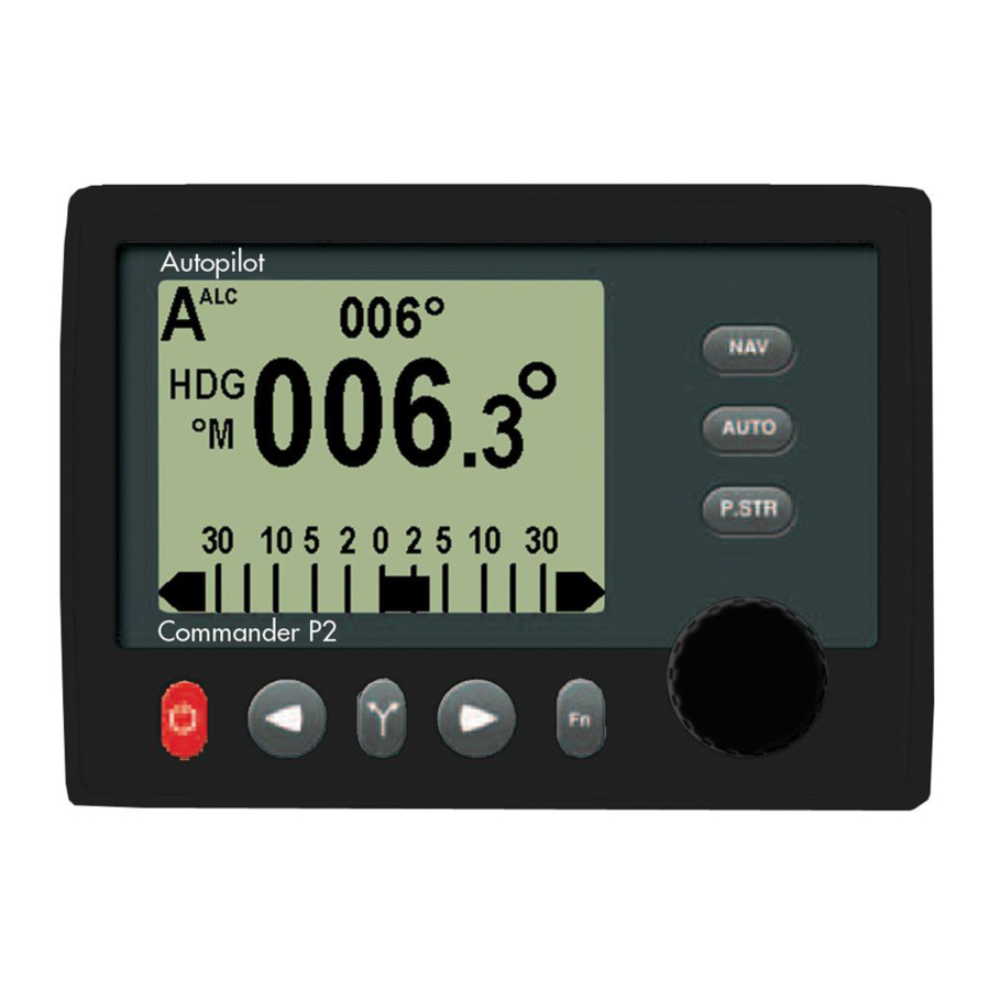
Page 28: Control Head
LCD display. Figure 4 – Control Head The Control Head, when shipped as part of a complete Commander P2 system, is a “core” module, with accessories for three mounting options: a snap-on sleeve for surface mounting, a separate snap-on sleeve for flush mounting, and a two-piece bracket for bracket mounting. -
Page 29: Signal Processor Unit
SPU continually checks all aspects of the autopilot’s performance, and will advise the user via the Control Head if any problems are encountered. Figure 5 – The Commander P2 SPU with Wiring & Diagnostic Covers Removed - 29 - Document PN 29010074 V3.1... -
Page 30: Compasses
Pitch/Roll on the Heading computation. The Vector is connected to the Commander P2 at one of the SPU’s two NMEA Input ports. The standard cable length is 15 metres (50’); 30 metres (100’) is also available. -
Page 31: Fluxgate Compass
This compass outputs the traditional analog compass signals – Sine & Cosine signals. It is supplied with a 12 metre (40’) cable; an adapter cable (PN311100024) is required to wire it into the Commander P2’s SPU. Figure 7 – Fluxgate Compass... -
Page 32: Magnetic Compasses
System Overview Magnetic Compasses ComNav offers several high quality externally gimballed Magnetic Compasses, of either 5” or 6” diameter, which are directly compatible with the ComNav Magnetic Compass Sensor. These compasses are available in either bracket mount or binnacle mount. Compensating spheres and arms are also available. -
Page 33: Heading Rate Stabilizer
ComNav recommends the use of ComNav’s own compasses for the best performance of the Commander P2 Advanced Autopilot system – but you certainly may decide to use either a fluxgate compass or a magnetic compass from another manufacturer. See your ComNav Dealer or consult the factory for information on interfacing these compasses with the Commander P2 system. -
Page 34: Rudder Followers
Standard Rotary Rudder Follower & Rudder Linkage PN 20330008 & 20330007 The ComNav Commander P2 is normally supplied with a ComNav Medium Duty Rotary Rudder Follower. The Rudder Follower is used to transmit the position of the vessel’s rudder to the SPU. It should be connected to whichever part of the steering system the autopilot controls. -
Page 35: Linear Rudder Follower
ComNav Commander P2 Installation & Operation System Overview Linear Rudder Follower PN 20330002 Installations on vessels with outboard motors may use a ComNav Linear Rudder Follower. Figure 14 – Linear Rudder Follower - 35 - Document PN 29010074 V3.1... -
Page 36: Auxiliary Controllers
ComNav Commander P2 Installation & Operation System Overview Auxiliary Controllers Up to two Auxiliary Controllers may be added to the standard Commander P2 system. These may be any combination of Commander Control Heads (colour and/or monochrome), CR-203 Handheld Remotes, and TS-203 Fixed Remotes. -
Page 37: Remote
TS-203. The kit’s ball & shaft are the same as used on ComNav Jog Levers. The total ball-shaft length is 12 cm (5”), as compared to the TS-203’s standard handle-shaft length of 18 cm (7”). -
Page 38: Other Controls, Indicators & Sensors
Rudder Angle Indicator (RAI) – 3” PN 20360014 The ComNav RAI is a backlit 3” (76 mm) diameter gauge that displays the actual position of the vessel’s rudder. The RAI is flush mounted, encased in high impact resistant polycarbonate plastic with a water resistant front face, and requires a lighting voltage supply of 12, 24 or 32 VDC. -
Page 39: Twin-Fin Wind Transducer
For use with sailboats, ComNav’s Twin-Fin Wind Transducer provides accurate wind speed and wind angle data to the Commander P2 SPU. This allows the vessel to steer to a specific angle relative to the wind. An easy, snap-in attachment for mast mounting is included. -
Page 40: Rudder Drives And Interfaces
Rudder Simulator which is used when the CT7 is interfaced to Azimuth Drives. The Commander P2’s SPU has built-in setup & operational firmware support for the CT7; the firmware activates automatically when a CT7 is plugged into the SPU at the J7 - T HRUSTER connector. -
Page 41: Other Drive Boxes
The Commander P2 system is capable of directly operating steering systems utilizing reversing DC motors or single speed solenoids. ComNav also manufactures a complete line of Drive Boxes that will interface the steering outputs from the Commander P2 system to almost any type of steering system. -
Page 42: Pumps & Drives
ComNav Commander P2 Installation & Operation System Overview Pumps & Drives ComNav offers several types of electric-motor Hydraulic Pumps, matching Solenoid Values & related equipment, as well as a number of high-quality Cable Drives and accessories. Each drive comes with its own Installation Manual. - Page 43 ComNav Commander P2 Installation & Operation Installation - 43 - Document PN 29010074 V3.1...
- Page 44 ComNav Commander P2 Installation & Operation - 44 - Document PN 29010074 V3.1...
-
Page 45: Installation
This chapter describes all the steps you must follow while doing the physical installation of the Commander P2 Advanced Autopilot System on your vessel. Each of the standard components of a P2 system is described – both physical mounting &... -
Page 46: Control Head
Mounting Each Control Head is supplied (when ordered as part of Commander P2 system kits) with three mounting kits -- one for bracket mounting (PN 30110006), one for surface mounting (PN 30110004), and one for flush-mounting (PN 30110003). Each one is packaged in a separate bag. -
Page 47: Compasses
A professional compass adjuster often does this job. If you intend to use a fluxgate compass other than a ComNav Fluxgate Compass, or if you are using a magnetic compass not supplied by ComNav, you should contact the dealer you purchased it from, or the manufacturer, for instructions on how to install and set up your compass. -
Page 48: Heading Rate Stabilizer
Excess cable should be coiled up. The cable may be shortened if desired to avoid excess coils. If the cable is too short, additional cable may be ordered from your ComNav Dealer. See Compasses on page 62 for further details on connecting the cable to the SPU. -
Page 49: Mounting
Ensure that there is sufficient slack in the cable to allow the compass bowl to tilt and rotate freely in all directions. Excess cable should be coiled up; ComNav recommends that the cable NOT be shortened. If the cable is too short, plug-in Compass Extension Cables are available in various lengths from your ComNav Dealer. -
Page 50: Rudder Follower
Rudder Follower in a location where the possibility of damage from any equipment stowed in the area is minimized. Note: If you are connecting the Commander P2 to a mechanical Cable Drive (for vessels that use cable steering instead of hydraulic steering), the rudder follower is built into the Cable Drive. -
Page 51: Electrical Connection
If the length of cable supplied is too short to reach all the way to the SPU, obtain a terminal strip and sufficient additional cable from your ComNav Dealer. Mount the terminal strip in a convenient DRY location where it will not be subjected to moisture of any kind. -
Page 52: Linear Rudder Follower
ComNav Commander P2 Installation & Operation Installation Linear Rudder Follower Mounting Step 1: If the Linear Rudder Follower is to be mounted with the sliding rod facing towards the port side of the vessel, turn the steering wheel so the motor is hard over to starboard. -
Page 53: Figure 26 - Band Clamp And Plastic Brackets
ComNav Commander P2 Installation & Operation Installation Step 3: The clamps and band should be positioned as far as possible towards the end of the Linear Rudder Follower which has the cable that goes to the autopilot (see Figure 25). Loosely place the stainless steel band clamp around the Linear Rudder Follower and the outboard’s... -
Page 54: Figure 28 - Fasteners, Stainless Bracket Arrangement
ComNav Commander P2 Installation & Operation Installation Step 4: Remove the nut from the steering cylinder rod’s end (see Figure 28). Place the thick nylon flat washer (1.57 mm / 0.062” thick), then the thinner nylon flat washer (0.81 mm / 0.032”... -
Page 55: Electrical Connection
If the length of cable supplied is too short to reach all the way to the SPU, obtain a terminal strip and sufficient additional cable from your ComNav Dealer. Mount the terminal strip in a convenient DRY location where it will not be subjected to moisture of any kind. -
Page 56: Signal Processor Unit
Undersized wiring will result in power losses which can affect overall efficiency and performance. Refer to the table below If in doubt, contact your ComNav Dealer for help. Function / Use... -
Page 57: Connectors On The Spu
ComNav Commander P2 Installation & Operation Installation Figure 29 – Removal of SPU Wiring Cover Connectors on the SPU With the wiring cover off, all the SPU’s connectors are visible (see Figure 5 & Figure 30). Each connector is a pin receptacle, with the pins sized according to how much current will be carried (bigger pins for higher current). -
Page 58: Wiring The System
ComNav Commander P2 Installation & Operation Installation Wiring the System Power Supply The ComNav Commander P2 will operate on any voltage between about 11 VDC and 30 VDC. This allows operation with vessel battery systems of nominal voltages from 12 to 24 VDC. Caution! Do not power up the SPU until you have completed the installation, and performed the steps outlined in “Post-Installation Checks”. -
Page 59: Figure 32 - Typical Battery Connection To Drive Boxes
ComNav Commander P2 Installation & Operation Installation Note: If your autopilot system utilizes one of ComNav’s CT Drive Boxes, it should be wired back to the breaker or fuse separately from the rest of the autopilot system. Do not “daisy- chain”... -
Page 60: Input & Output Connections
Input & Output Connections Control Head Two types of control cable are used in manufacturing Commander P2 systems. The only difference between them is the colour-coding of the wires. Wire the cable from the main Control Head onto the nine-position plug-in connector according to the following diagram: Figure 34 –... -
Page 61: Jog Levers
Four-Way Valves, Used with Jog Levers If the Commander P2 is being used with four-way solenoid-activated valves (see page 67), it is also possible to wire Jog Levers so that they may be used even when the autopilot is not powered on. -
Page 62: Compasses
Figure 37 – Wiring Connections for Analog Compasses If you have a 45° Compass Transducer with your Commander P2 SPU, it is also connected to the eleven-position plug that fits into the J8 receptacle. Wire as per the following diagram. -
Page 63: Wind Transducer
ComNav Commander P2 Installation & Operation Installation Wind Transducer If you are connecting a ComNav Twin-Fin Wind Transducer to the Commander P2 SPU, it must also be connected to the eleven-position plug that fits into the J8 – C receptacle. -
Page 64: Rudder Follower
ComNav Commander P2 Installation & Operation Installation Figure 41 – Wind Transducer with Classic Nexus or NX2 Network Server Rudder Follower The Rudder Follower is connected to the four-position receptacle on the SPU labelled J4 – R . Wire the Rudder Follower to the plug-in connector as per the... -
Page 65: Rudder Angle Indicators
Installation Rudder Angle Indicators The Commander P2 system will drive up to five 500 microampere Rudder Angle Indicator (RAI) meters – such as those supplied by ComNav (PN 20360014). Mounting instructions are included with each meter. Wire the meter to the plug for the SPU receptacle labelled J5 –... -
Page 66: Drive Outputs
To connect the pump motor directly to the SPU, use the following diagram. Note that wire polarity is not important, since the Commander P2 will automatically make the necessary adjustments internally when the system is set up. -
Page 67: Shunt-Field Reversing Motors
ComNav Commander P2 Installation & Operation Installation Shunt-Field Reversing Motors For shunt-field reversing motors, connect the shunt field coil positive terminal to SW’D B+ and the coil negative terminal to SW’D GND as per the following diagram: Figure 46 – Wiring Connections for Shunt Field Reversing Motors Standard Four-Way Solenoid-Activated Hydraulic Valves Connection to 12 VDC or 24 VDC solenoids should be made as per the following diagram. -
Page 68: Two-Speed Solenoid Valves
Two-Speed Solenoid Valves ComNav’s CT5 Drive Box (PN 20350004) should be used to interface between the Commander P2 SPU and two-speed solenoid systems. Connect the CT5 to the SPU as per the instructions shipped with the CT5, and the following diagram: Figure 49 –... -
Page 69: A.c. Solenoids
A.C. Solenoids ComNav’s CT4 Drive Box (PN 20350003) should be used to interface between the Commander P2 SPU and A.C. solenoid systems. Connect the CT4 to the SPU as per the instructions shipped with the CT4, and the following diagram: Figure 50 –... -
Page 70: Azimuth Drives, Surface Piercing Drives And Jet Drives
Figure 52 – Wiring Connections for Isolation Amplifiers The ComNav CT7 Thruster Interface (see page 40) can also be used with some of these types of drives. See the CT7’s Installation & Operation Manual for wiring instructions. -
Page 71: External Alarm Output
Installation External Alarm Output An external alarm can be connected to the Commander P2 SPU. The autopilot can be configured to activate the external alarm whenever an alarm or error message appears on the Control Head. You can modify the configuration to activate the external alarm only if the Watch Alarm is not answered (as opposed to activating it for all alarms). -
Page 72: Figure 55 - External Alarm, Sw'd B- Output - With Power Fail Option
ComNav Commander P2 Installation & Operation Installation Some installations require separate monitoring for power failures. This can be accomplished with the following circuit, which utilizes two relays. The coil voltage of the relays should match the supply voltage for the autopilot. The Alarm Supply, which must be a separate, dedicated supply from the autopilot supply, should match the voltage of the alarm. -
Page 73: Nmea 0183 Input & Output
– have outputs complying with NMEA 0183. Two such devices can be connected directly to the Commander P2 SPU, by wiring them into the plug mated to the receptacle labelled J9 – NAV I/O. -
Page 74: Pc Input & Output
Table 2 – NMEA Signal Translation Guide PC Input & Output The Commander P2 system can be connected to a desktop or laptop Personal Computer which is running navigation software. The following diagrams show how to do this: Figure 58 – Connection to a PC with a DE-9 Connector Figure 59 –... -
Page 75: Other Connections
ComNav Commander P2 Installation & Operation Installation Other Connections Miscellaneous I/O The J6 – M connector is reserved for possible future use. The receptacle is ISCELLANEOUS supplied with a 10-pin mating plug. Thruster Interface The J7 – T I’ F connector is used with the CT7 Thruster Interface. -
Page 76: Post-Installation Checks
Post-Installation Checks Be sure to perform all of the Electrical and Hydraulic checks listed below before using the Commander P2 Advanced Autopilot System for the first time. Electrical Checks Once you have completed the wiring of the Autopilot System, perform the following checks to ensure that the installation is complete and that the autopilot has been installed in a safe and secure manner. -
Page 77: Hydraulic Checks
3) Check that when the steering wheel is turned to port, the rudder moves so as to turn the vessel to port. 4) If you have installed a ComNav Marine Reversing Motor Pump, a Constant Running Pump or an Engine Driven Pump: ⇒... - Page 78 ComNav Commander P2 Installation & Operation - 78 - Document PN 29010074 V3.1...
- Page 79 ComNav Commander P2 Installation & Operation Getting Started - 79 - Document PN 29010074 V3.1...
- Page 80 ComNav Commander P2 Installation & Operation - 80 - Document PN 29010074 V3.1...
-
Page 81: Getting Started
Power On/Off The first step in using your Commander P2 system is to turn it on … To turn on the Commander P2 system, press & hold the Control Head’s red STANDBY/ON/OFF button, until the introductory display (see Figure 61) appears, then release the button. -
Page 82: Using The Control Head - Lcd Screen & Buttons
Figure 61 – Using the Control Head The elements of the Control Head (with reference to the identifiers above) are: 1) LCD Screen. As long as the Commander P2 system is powered on, the LCD screen normally displays the compass heading, rudder angle, and mode of operation;... - Page 83 AUTO or NAV modes. Double-pressing the button will bring up (or cancel) the Work mode menu. • If the Commander P2 is installed on a sailboat, this button invokes WIND mode while in AUTO mode. Double-pressing the button will bring up (or cancel) the Wind mode menu.
-
Page 84: Operating Modes & Menus
Getting Started Operating Modes & Menus Your ComNav Commander P2 Advanced Autopilot System has four basic operating modes, known as STANDBY, POWER STEER, AUTO, and NAV; a fifth operating mode, known as WORK, is a sub-mode of AUTO & NAV modes, and is available on all vessel types except sailboats. -
Page 85: Alarm Clear
Alarm Clear Whenever an alarm or error message occurs on the Commander P2, an audible alarm will sound, both at the SPU & at the Control Head, and a message will be displayed on the LCD. -
Page 86: Dockside Setup Menu
Typically, it is used only infrequently after initial setup. A special button sequence must be used to access the Dockside Setup menu: 1) Start with the Commander P2 system powered off. 2) Press and hold the button and the TURN button. Then press & hold the STANDBY/ON/OFF button. -
Page 87: Reset
. Use this feature WILL BE LOST only on the advice of an authorized ComNav service representative. Vessel Type Set this to most closely match the type of vessel that the autopilot is installed on. The system then automatically uses a set of steering parameters that have been found to work reasonably well with typical vessels of the chosen type. -
Page 88: An. Comp. Type (Analog Compass Type)
Analog Compasses that output DC sine and cosine signals. The An. Comp. Type parameter tells the Commander P2 what specific type of analog compass is connected to the SPU (or if none is). Analog compasses are always connected to J8 on the SPU. Refer to the following table for help in identifying and selecting the correct type for the compass in your system. -
Page 89: Compass Setup
Compass Setup Pressing the button when this item is highlighted tells the Commander P2 to verify the Analog Compass connections. If the connections are found to be correct, the autopilot will then query whether you want it to do an automatic compensation of the compass for Magnetic Deviation. -
Page 90: Figure 66 - External Alarm Configuration
ComNav Commander P2 Installation & Operation Getting Started To configure the External Alarm Output, follow these steps: 1) Highlight “Alarm O/P” on the screen. 2) Use the COURSE CHANGE knob to select the Alarm O/P that you want to use. -
Page 91: Thrust Type
Getting Started Thrust Type Thrust MIN Thrust MAX If the optional CT7 Thruster Interface is installed with your Commander P2 system, you will need to make adjustments to these settings. Complete instructions are included with the CT7 Thruster Interface. Language This parameter allows you to set the language used for almost all menus &... -
Page 92: Setup Procedures
ComNav Commander P2 Installation & Operation Getting Started Setup Procedures Once your Commander P2 autopilot system is installed, you must set it up, before you can use it. • First, you must tell the P2 what type of vessel you have, and then have the P2 determine the characteristics of the Rudder Drive mechanism on the vessel. -
Page 93: Drive Setup
4) Once the rudder is hard-over, press the STARBOARD ARROW button. Next, the Commander P2 will prompt you to move the rudder all the way over to the port side. -
Page 94: Figure 70 - Move Rudder To Port
ComNav Commander P2 Installation & Operation Getting Started Figure 70 – Move Rudder to Port The Commander P2 will quickly measure the rudder position again, and then prompt you to move the rudder to the centre position. • Do so - again, the speed at which you move the rudder does not matter, nor does some back &... -
Page 95: Bleeding A Hydraulic Steering System
Getting Started Bleeding a Hydraulic Steering System The Commander P2 will pause the Drive Setup process at this point, and prompt you to bleed your hydraulic steering system. Note: If you do not have a hydraulic system, just press the... -
Page 96: Figure 73 - Bleeding Cylinder, Rod Moving Left
5. Position yourself so that you can see the hydraulic cylinder while operating the Commander P2 Control Head. You can move the steering cylinder rod with the P2’s Drive outputs, by pressing either the PORT or STARBOARD ARROW button on the Control Head. -
Page 97: Drive Setup (Continued)
6) When you press the button (when the “Bleed?” screen was displayed, after bleeding the hydraulic system, or if you skipped that step), the Commander P2 will fully test the drive system. This involves the autopilot automatically running the rudder from hard-over to hard-over a number of times, and possibly making some speed adjustments to the reversing motor pump-set (if one is installed on your system). -
Page 98: Compass Setup - Dockside
ComNav Commander P2 Installation & Operation Getting Started Compass Setup – Dockside The first steps in setting up your compasses are to select which type (or types) you have, and to verify that they are properly wired to the SPU. -
Page 99: Figure 77 - Compass Verification (Mag Sensor Shown)
Figure 77 – Compass Verification (Mag Sensor shown) • If the Commander P2 system could not find a compass that matches with the type you have selected in step 1), it will give the following error message at this point (the type of compass shown will depend on what you entered for “An. -
Page 100: Compass Setup - On The Water
4) Select Compass Setup & press the button. 5) After the Commander P2 has auto-detected the compass, it will ask you if you want to SET NORTH NOW? (see Figure 77). Press the STARBOARD ARROW button. Manually steer the vessel so that it is pointing to Magnetic North. Hold it on that heading and push the button. -
Page 101: Heading Rate Stabilizer
ComNav Commander P2 Installation & Operation Getting Started Heading Rate Stabilizer If you have a ComNav Heading Rate Stabilizer with your Fluxgate compass, you must first compensate the HRS, and then compensate the compass. • If you do not have an HRS with your Fluxgate Compass, skip to the Fluxgate Compass procedure, on the next page. -
Page 102: Fluxgate Compass
4) Select Compass Setup & press the button. 5) After the Commander P2 has auto-detected the compass (or HRS), it will prompt you whether or not you want to compensate it. Press the STARBOARD ARROW button. Figure 79 – Fluxgate Compass Verification & Compensation 6) Manually steer the vessel in a circle. -
Page 103: 45° Compass Transducer
3) Select Compass Setup & press the button. 4) After the Commander P2 has auto-detected the Compass Transducer (shown as NX2 COMPASS FOUND), it will prompt you whether or not you want to compensate it. Press the STARBOARD ARROW button. -
Page 104: Compass Calibration
Any or all of your compasses may still have an individual fixed offset, so you must tell the Commander P2 SPU what each one’s calibration value is. Calibration is a simple matter of synchronizing each compass’s directional readings, as seen by the SPU, to the actual Magnetic direction values of the Earth’s magnetic field. -
Page 105: Sea Trials
These group labels are chosen because speed is often the single biggest factor in vessel dynamics. The Commander P2 has been tested on a wide variety of vessels of different types and sizes. The default settings for the steering parameters – for each Vessel Type listed in the Dockside Setup menu –... -
Page 106: Adjust Seastate For Low Speed
ComNav Commander P2 Installation & Operation Getting Started 9) Make a 40° course change. • If the vessel stops turning before the new heading is reached and then approaches it slowly, either ◊ increase Rudder Gain by 1 level ◊... -
Page 107: Adjusting For Sea Conditions
Adjusting the steering parameters in calm conditions – as you do during the initial part of the Sea Trials – gives a base reference for all other conditions. As you get the overall setup of the Commander P2’s operating parameters closer to being perfect, you can then venture into rougher conditions. - Page 108 ComNav Commander P2 Installation & Operation - 108 - Document PN 29010074 V3.1...
- Page 109 ComNav Commander P2 Installation & Operation Basic Operations - 109 - Document PN 29010074 V3.1...
- Page 110 ComNav Commander P2 Installation & Operation - 110 - Document PN 29010074 V3.1...
-
Page 111: Basic Operations
The thin solid bar below the rudder position bar shows the rudder travel limits (see page 115). Whenever the Commander P2 is moving the vessel’s rudder to Port or Starboard, a small “pointer” symbol will be shown at the corresponding end of the RAI. -
Page 112: Standby Menu
There are a number of separate inputs for different types of compasses that may be used with the Commander P2 system. You may elect to have more than one type connected at the same time. This menu item allows you to switch from one to another at any time. -
Page 113: Compass Cal (Compass Calibration)
Watch Alarm The Commander P2 has a built-in Watch Alarm. This menu item allows you to turn on the Watch Alarm and set how much time is allowed to elapse before the alarm goes off. This menu item is “password protected”... -
Page 114: Power Steer Mode
ComNav Commander P2 Installation & Operation Basic Operations Power Steer Mode To enter POWER STEER mode, press and hold the P.STR button for about a half-second, until the large “P” mode indicator appears in the upper left corner of the display. -
Page 115: Power Steer Menu
Figure 84 – Power Steer Menu Stdby/P.Str Limits (Power Steer Rudder Limits) When you set up the Commander P2 system (see Setup Procedures on page 92), you will move the rudder from hard over port to hard over starboard so that the autopilot can measure these positions. -
Page 116: Auto Mode
To enter AUTO mode, press and hold the AUTO button for about a half- second, until a large letter “A” is shown in the upper left portion of the display. The Commander P2 will start to steer the vessel to the heading that the vessel was on at the moment that AUTO mode was entered. -
Page 117: Auto Menu
Rudder Gain is a measure of the amount of corrective rudder that will be applied for a given course error. The Commander P2 is able to accommodate a wide range of rudder gains, but restricts the user to a certain portion of this range, depending on the type of vessel the autopilot is installed on. -
Page 118: Counter Rudder
ComNav Commander P2 Installation & Operation Basic Operations Counter Rudder Counter Rudder is a measure of how much rudder is applied for a given rate of change in course error. If the course error is increasing, the counter rudder adds to the rudder correction, and if the course is decreasing the counter rudder subtracts from the rudder correction applied. -
Page 119: Parameter Set
ComNav Commander P2 Installation & Operation Basic Operations Parameter Set The Commander P2 gives you the ability to store two sets of steering parameters, labelled “Hi” (high) and “Lo” (low). This allows for best performance under varying vessel speeds and/or loading conditions. -
Page 120: Nav Mode
NMEA 0183 Navigation System, to steer to a destination, or along a route of waypoints leading to a final destination. In NAV mode the Commander P2 uses its own compass (or the Navigation System) as its primary source of heading for course keeping, while the steering data received from the Navigation System is used to calculate the commanded heading to the destination or next waypoint. -
Page 121: Nav Menu
When the vessel arrives at a waypoint or the end of a route, a special “arrival” message is sent to the autopilot from the Navigation System. This menu item tells the Commander P2 how you want to deal with the arrival message. -
Page 122: Correction
(R)ight indicator to mean the opposite. Because of this confusion, the Commander P2’s handling of XTE can be switched from “Norm” (normal) to “Rev” (reverse). In “Norm”, the autopilot will respond normally to the sense of the cross-track error. -
Page 123: Commanded Heading Displayed
Navigation System. This is because there are three different methods that the Commander P2 can use to process and react to the navigation data from the Navigation System. You select which method you want the Commander P2 to use by specifying “XTE”, “CTS”, or “Both”... -
Page 124: Correction Set To Xte - Cross-Track Error Steering
3) Switch the autopilot to STANDBY mode and manually steer the vessel onto the track. 4) Place the Commander P2 into NAV mode by pressing and holding the NAV button until the unit beeps and the letter “N” appears in the upper left portion of the display. -
Page 125: Figure 94 - Response Of Vessel To A Large Cross-Track Error
ComNav Commander P2 Installation & Operation Basic Operations The course steered when Correction is set to “XTE” may not be the most efficient in terms of overall distance traveled. If there is a large cross-track error, the autopilot may overshoot the intended track. This is a function of turn rate, vessel speed, and position updates received from the Navigation System. -
Page 126: Correction Set To Both - Steering To/Along A Track
Basic Operations Correction set to Both – Steering To/Along a Track In this method, the Commander P2 will bring the vessel onto the track as smoothly and efficiently as possible. It does this by combining aspects of steering, using cross-track error, bearing from original to destination, and bearing directly to the waypoint. - Page 127 ComNav Commander P2 Installation & Operation Basic Operations You can test out how well the Commander P2 steers along a track by following these steps: 1) Make sure the Navigation System is turned on and that a waypoint is programmed in.
-
Page 128: Alternate Nav Display
ComNav Commander P2 Installation & Operation Basic Operations Alternate NAV Display An alternative display is available for NAV mode. To access this display, enter NAV mode by pressing the NAV button until the letter “N” appears in the upper left portion of the display. -
Page 129: Dodge
Pressing & maintaining either the PORT ARROW button or STARBOARD ARROW button will cause the Commander P2 to turn the vessel in that direction. As long as one of the buttons is pressed, the rudder will keep moving in the corresponding direction. -
Page 130: Figure 98 - Vessel Track During A Dodge Manoeuvre In Auto Mode
ComNav Commander P2 Installation & Operation Basic Operations Note: if you dodge the vessel in AUTO or WORK modes, then when you release the PORT or STARBOARD ARROW button, the vessel will return to the same Heading – but not the same Track. The new Track will be offset from the original Track by the distance traveled during the Dodge manoeuvre. -
Page 131: Figure 99 - Holding At A Heading Part-Way Through A Dodge Turn
ComNav Commander P2 Installation & Operation Basic Operations You can bring the rudder back to centre (Dead Ahead) part-way through a Dodge. For example, you might want to center the rudder in order to maintain, for a while, a specific Heading that the vessel has reached during the dodge. -
Page 132: Jog Lever Turns
If a Jog Lever is connected to the SPU terminal block J3, you can directly change the vessel’s heading with that Lever, while the Commander P2 is in POWER STEER mode, in AUTO mode, in NAV mode, or in WORK or WIND modes. - Page 133 ComNav Commander P2 Installation & Operation Advanced Operations - 133 - Document PN 29010074 V3.1...
- Page 134 ComNav Commander P2 Installation & Operation - 134 - Document PN 29010074 V3.1...
-
Page 135: Advanced Operations
WORK mode. ⇒ The Commander P2 has an automatic Off-Course Alarm that will be activated should the vessel fall off the commanded heading, in WORK mode, by more than 20°. There is a 32 second delay on this alarm. -
Page 136: Manual Work Mode
ComNav Commander P2 Installation & Operation Advanced Operations When WORK mode is engaged, the Rudder Scale Factor will multiply the Rudder Gain setting. Normally the rudder is moved an amount proportional to the course error detected (i.e., the error times the Rudder Gain); in WORK mode, that calculation will also be multiplied by the Scale Factor, resulting in larger rudder movements for a given course error. -
Page 137: Work Menu
Autotrim The Commander P2’s WORK mode can be configured to use manual or automatic rudder bias when in WORK mode (the default is to use automatic rudder bias). Manual rudder bias is fixed by the position of the rudder when the autopilot first enters WORK mode, but can be adjusted by the user if desired (see Rudder Bias, above). -
Page 138: Wind Mode
In order to use WIND mode, your autopilot must be equipped with a ComNav Twin-Fin Wind Transducer, or it must receive wind information in the form of NMEA 0183 data via one of the NAV data inputs. -
Page 139: Tacking
These angles can be changed via the Wind menu. Attempts to change the commanded wind angle beyond these points of sail will be ignored by the Commander P2. This is a safety feature known as Tack and Gybe Inhibits. Caution! Tack and Gybe Inhibits are not a guarantee against hazardous situations. -
Page 140: Figure 105 - Tack Response For Various Points Of Sail
• The Commander P2 will only tack the boat if you are at or near the Close Haul Def Point. If the wind angle is greater, then when you press the PORT or STARBOARD ARROW button (depending on which tack you are on), the autopilot will steer the boat to the Close Haul Def Point on the same tack, and hold it there. -
Page 141: Gybing
ComNav Commander P2 Installation & Operation Advanced Operations Gybing Gybing is only possible when the wind angle is at the Broad Reach Def Point or greater. Gybing is performed in much the same way as a tack; simply press the TURN button followed by the appropriate ARROW button. -
Page 142: Alternate Wind Mode Display
ComNav Commander P2 Installation & Operation Advanced Operations Alternate WIND Mode Display There is an alternative to the regular WIND mode, called Alternate WIND mode. In this mode, the COURSE CHANGE knob is used to command the autopilot to steer to specific predefined points of sail: Close Haul, Close Reach, Beam Reach, Broad Reach, or Gybe Hold Point. -
Page 143: Figure 108 - Commanded Wind Angle Changed To 90
60°, and the outline arrow will be replaced with a solid one. Figure 109 – Arrow Outline Shows Commanded Wind Angle The Commander P2 will not allow you to Tack or Gybe using the COURSE CHANGE knob, when the alternative wind display is shown. -
Page 144: Wind Menu
Figure 110 – Wind Menu, pages 1 & 2 Wind Source Wind data may be received either directly from a ComNav Twin-Fin Wind Transducer, or from other devices that provide wind data in NMEA 0183 format. Select the appropriate value... -
Page 145: Wind Shift (Wind Shift Alarm)
Wind Shift Delay The Commander P2 can warn you if the wind shifts significantly. For example, if the Wind Shift alarm is set to 10 and the Wind Shift Delay is set to 0.5, then if the wind shifts by more than 10 degrees for 0.5 minutes, the Wind Shift Alarm will sound. -
Page 146: Special Turns
Advanced Operations Special Turns There are a number of Special Turns pre-programmed into the Commander P2 system. Special Turns can be executed only in AUTO, WORK & WIND modes. To execute a Special Turn (with the autopilot in the appropriate mode): 1) Press the TURN button. -
Page 147: U-Turn
ComNav Commander P2 Installation & Operation Advanced Operations U-Turn Figure 112 – U-Turn Query Figure 113 – U-Turn Vessel Path The autopilot calculates a reciprocal course to the vessel’s heading, and then turns the vessel to that heading, in the appropriate direction, once the PORT or STARBOARD ARROW button is pressed. -
Page 148: Circle Turn
ComNav Commander P2 Installation & Operation Advanced Operations Circle Turn Figure 114 – Circle Turn Query Figure 115 – Circle Turn Vessel Path The autopilot steers a never-ending circle in the appropriate direction once the PORT or STARBOARD ARROW button is pressed. The Turn Rate setting in the Auto menu governs the rate of turn. -
Page 149: M.o.b. - Man Over-Board
ComNav Commander P2 Installation & Operation Advanced Operations M.O.B. – Man Over-Board Figure 116 – M.O.B. Turn Query Figure 117 – M.O.B. Turn Vessel Path The autopilot will perform a Williamson Man Overboard turn, sometimes known as an Emergency or E-turn. This will bring the vessel onto a reciprocal heading; typically right down the vessel’s own wake. -
Page 150: Fishzag
ComNav Commander P2 Installation & Operation Advanced Operations Fishzag Figure 118 – Fishzag Turn Query Figure 119 – Fishzag Turn As its name implies, the Fishzag turn was developed specifically for fishing. When this Special Turn is executed, the autopilot maintains the present course for the time interval specified by the Fishzag Timer in the Standby menu. -
Page 151: Pretack (Preset-Tack)
ComNav Commander P2 Installation & Operation Advanced Operations Pretack (Preset-Tack) Figure 120 – PreTack Turn Query Preset-Tack Special Turns are only available in AUTO mode, and if the Vessel Type in the Dockside Setup menu is set to Sail. The Preset-Tack turn will turn the vessel the number of degrees specified by the Pretack Angle in the Wind menu. -
Page 152: Tack
ComNav Commander P2 Installation & Operation Advanced Operations Tack Figure 121 – Tack Query in Regular (left) and Alternate (right) AUTO-WIND Modes Tack Special Turns are only available in WIND and Alternate WIND modes. • If the vessel is sailing close to the angle of wind defined by the Close Haul Def parameter in the Wind menu, the autopilot will turn the boat to a close-hauled position on the opposite tack. -
Page 153: Gybe
ComNav Commander P2 Installation & Operation Advanced Operations Gybe Figure 122 – Gybe Query in Regular (left) and Alternate (right) AUTO-WIND Modes Gybe Special Turns are only available in WIND and Alternate WIND modes. • If the vessel is sailing close to the angle of wind defined by the Gybe Hold Pt. parameter in the Wind menu, the autopilot will turn the boat to the Gybe Hold Pt. -
Page 154: Multiple Control Heads & Auxiliary Controllers
Multiple Control Heads & Auxiliary Controllers Two additional Control Heads or Auxiliary Controllers may be added to the standard Commander P2 system. These may be any combination Commander Control Heads, CR-203 Handheld Remotes, or TS-203 Fixed Remotes. Only one Control Head or Auxiliary Controller may be In-command at any given time. When the autopilot system is first powered on, the main Control Head, connected to J11 of the SPU, will always be In-command. -
Page 155: Watch Alarm
Advanced Operations Watch Alarm The Watch Alarm is a special timer that is built into the Commander P2 autopilot. It measures how long it has been since any of the buttons on the Control Head have been pressed. If the time exceeds the amount set for the Watch Alarm parameter in the Standby menu, an alarm is set off to alert the helmsman. -
Page 156: Entering The Password
ComNav Commander P2 Installation & Operation Advanced Operations Entering the Password When you attempt to change the Watch Alarm timer, (highlight “Watch Alarm” in the Standby menu, then turn the COURSE KNOB in either direction), the Control Head responds by showing a special pop-up box on the LCD screen with the query “Password?”... -
Page 157: Changing The Password
ComNav Commander P2 Installation & Operation Advanced Operations Changing the Password As mentioned above, the autopilot is shipped from the factory with a null password, which means that the password sequence consists of simply pushing the STANDBY/ON/OFF button when prompted by the “Password?” query in the pop-up window. To prevent unauthorized personnel from tampering with the Watch Alarm, it is recommended that you change the password sequence from the default null password. - Page 158 ComNav Commander P2 Installation & Operation - 158 - Document PN 29010074 V3.1...
- Page 159 ComNav Commander P2 Installation & Operation Care & Maintenance - 159 - Document PN 29010074 V3.1...
- Page 160 ComNav Commander P2 Installation & Operation - 160 - Document PN 29010074 V3.1...
-
Page 161: Care & Maintenance
ComNav Commander P2 Installation & Operation Care & Maintenance Care & Maintenance The Commander P2 Advanced Autopilot System has been designed to provide many years of reliable service. The following periodic care and maintenance tips will help to ensure the longevity of your autopilot. -
Page 162: Fuse Replacement
ComNav Commander P2 Installation & Operation Care & Maintenance Fuse Replacement There are two fuses used on the SPU. Replace fuses only with the same type and rating, as per the table below. Should a fuse blow, determine the cause before replacing. - Page 163 ComNav Commander P2 Installation & Operation Appendices - 163 - Document PN 29010074 V3.1...
- Page 164 ComNav Commander P2 Installation & Operation Appendices - 164 - Document PN 29010074 V3.1...
-
Page 165: Appendices
The Commander P2 Advanced Autopilot system receives and transmits serial data in NMEA 0183 format. Messages Accepted The Commander P2 accepts the following NMEA 0183 sentences (the ‘*’ in front of the sentences indicates that the TALKER Identifier is always ignored): Sentence... -
Page 166: Table 9 - Nmea Sentence Priority
ComNav Commander P2 Installation & Operation Appendices All sentences received must have valid checksums. Sentences which do not have any checksums, or have invalid checksums, will be ignored. In some cases, if the missing/invalid condition persists long enough, an INVALID CRS DATA, SPEED DATA, &/or HEADING error will occur (see page 170). -
Page 167: Messages Transmitted
‘M’), from that sentence. Messages Transmitted The Commander P2 outputs NMEA 0183 compliant data (at 4800 Baud, on the OUT A/B pins of the J9 – NAV I/O connector), which may be used by NMEA 0183 compliant LISTENERS, or may be used to observe &/or record various Commander P2 parameters, for diagnostic purposes, while the system is running. - Page 168 ComNav Commander P2 Installation & Operation Appendices - 168 - Document PN 29010074 V3.1...
-
Page 169: Error Messages
Appendices Appendix 2 Error Messages There are a number of different error messages in the Commander P2 autopilot system. These messages are displayed on the Control Head screen, and are usually accompanied by an audible alarm. The following errors are classified as warnings. Operation of the autopilot continues normally. -
Page 170: Table 11 - Error Messages
They are automatically cancelled should the condition that caused them be removed. Message Description The Commander P2 cannot read the Analog compass specified in COMPASS ERROR the Standby menu under Compass Source. Check compass wiring. The Commander P2 SPU has detected a problem in FAULTY AUX #1 communicating with the Control Head connected to J12 –... -
Page 171: Table 12 - Critical Error Messages
~10 VDC, which is too low LOW BATTERY to continue safe operation. Check all wiring and the battery(ies). The Commander P2 has detected a problem in its ROM ERROR program memory. Return the unit to your ComNav Dealer for repair. - Page 172 ComNav Commander P2 Installation & Operation Appendices - 172 - Document PN 29010074 V3.1...
-
Page 173: Auxiliary Head / Remote Power On
Appendix 3 Auxiliary Head / Remote Power On The Commander P2 SPU is shipped from the factory configured so that power can only be turned on or off from the main Control Head. The main Control Head is designated as that which is plugged into the SPU receptacle labelled "J11 - Control Head”. - Page 174 ComNav Commander P2 Installation & Operation Appendices - 174 - Document PN 29010074 V3.1...
-
Page 175: Diagnostic Leds
ComNav Commander P2 Installation & Operation Appendices Appendix 4 Diagnostic LEDs The Signal Processor Unit is equipped with a number of Light-Emitting Diode (LED) lamps that can assist in trouble-shooting should a problem arise with the autopilot system. To observe the LEDs, remove the metal cover on the Diagnostic section. - Page 176 ComNav Commander P2 Installation & Operation Appendices - 176 - Document PN 29010074 V3.1...
-
Page 177: Upgrading Firmware
ComNav is constantly doing research and development related to our Autopilot Systems. From time to time, this can result in new features and benefits that can be incorporated into an existing system installation, in the field – by a ComNav Dealer, or even by the vessel operator. - Page 178 ComNav Commander P2 Installation & Operation Appendices - 178 - Document PN 29010074 V3.1...
-
Page 179: General Specifications
ComNav Commander P2 Installation & Operation Appendices Appendix 6 General Specifications Parameter Specification Dimensions 257 x 184 x 78 mm (10.1 x 7.3 x 3.1”) Bracket Mount Head 157 x 118 x 73 mm (6.2 x 4.6 x 2.9”) @ 20° max tilt –... -
Page 180: Compass Safe Distances
ComNav Commander P2 Installation & Operation Appendices Compass Safe Distances The following Compass Safe Distances were determined using a UKAS calibrated 23 Axis Magnetometer, for both standard compasses and steering/emergency compasses. Standard Steering Compass Compass ComNav PN Description Limit Limit 5.4°/H... -
Page 181: Ce Compliance
Immunity to Earth Lead Coupling Annex A, Section A.6: Immunity to Radiated Interference Test results and a declaration of conformity are on file at the ComNav Head Office. ComNav Marine Ltd. #15 - 13511 Crestwood Place Richmond, BC V6V 2G1... - Page 182 ComNav Commander P2 Installation & Operation - 182 - Document PN 29010074 V3.1...
- Page 183 ComNav Commander P2 Installation & Operation Index - 183 - Document PN 29010074 V3.1...
- Page 184 ComNav Commander P2 Installation & Operation - 184 - Document PN 29010074 V3.1...
-
Page 185: Index
ComNav Commander P2 Installation & Operation Index Index Checks – Residual air..........75 – 4 – Circle Turn ..............146 Close Haul ..............140 45° Compass Transducer......30, 46, 60, 101 Close Haul Def ............143 Close Reach .............. 140 Close Reach Def ............ - Page 186 ComNav Commander P2 Installation & Operation Index Fluxgate Compass......... 29, 45, 100 – N – Four-Way Hydraulic Valves ......... 65 Four-Way Valves, Used with Jog Levers..... 59 NAV button..............81 FUNCTION (Fn) button ..........81 NAV Input & Output ............. 71 Fuse Replacement ............
- Page 187 ComNav Commander P2 Installation & Operation Index Rudder Limits ............87, 113 – U – Rudder Scale Factor ..........134, 135 Upgrading Firmware ..........175 User Notes..............192 – S – User Settings ............. 189 U-Turn................ 145 Scale................126 Sea Conditions ............105 Sea Trials ............45, 90, 103 –...
- Page 188 ComNav Commander P2 Installation & Operation - 188 - Document PN 29010074 V3.1...
- Page 189 ComNav Commander P2 Installation & Operation User Notes & Settings - 189 - Document PN 29010074 V3.1...
- Page 190 ComNav Commander P2 Installation & Operation - 190 - Document PN 29010074 V3.1...
-
Page 191: User Notes & Settings
ComNav Commander P2 Installation & Operation User Notes & Settings User Settings Once your Commander P2 system has been installed and set up correctly, make a record of all the settings for future reference, in the table below. Parameter Range... - Page 192 User Notes & Settings ComNav Commander P2 Installation & Operation Parameter Range Default Value User Settings 1 User Settings 2 Power Steer Menu Stdby/P.Str Rudder Off, or 5° up to physical limits Limits from Dockside Setup Auto/Nav Rudder Off, or 5° up to physical limits...
-
Page 193: Table 16 - User Settings
User Notes & Settings ComNav Commander P2 Installation & Operation Parameter Range Default Value User Settings 1 User Settings 2 Work Menu Auto/Nav rudder limit or physical Rudder Bias Set at Runtime limit Autotrim Off, On Work Trip Pt. 1 – 10 Rudder Scale 0.25 –... - Page 194 User Notes & Settings ComNav Commander P2 Installation & Operation User Notes - 194 - Document PN 29010074 V3.1...
Need help?
Do you have a question about the Commander P2 and is the answer not in the manual?
Questions and answers