Table of Contents
Advertisement
Quick Links
Installation and Operation Manual
NOTE: In the case of differences of interpretation as regards the terms used in various translations of this manual,
the English version shall be regarded as correct and shall supersede all other versions.
This manual may not be reproduced in whole or in part without written permission from ComNav Marine Ltd.
ComNav Marine Ltd.
15 - 13511 Crestwood Place, Richmond, BC, Canada V6V 2G1
Phone: (604) 207-1600 Fax: (604) 207-8008
Internet: www.comnavmarine.com e-mail: comnav@comnavmarine.com
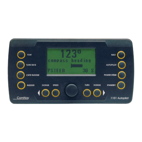
ComNav 1101 Autopilot
1101 Autopilot System
Version 6.0
Serial #
Copyright © 2004 by ComNav Marine Ltd.
Printed in Canada
Document PN
29010009
06/11/02
Advertisement
Table of Contents

Subscribe to Our Youtube Channel
Related Manuals for ComNav 11101


Summary of Contents for ComNav 11101
- Page 1 English version shall be regarded as correct and shall supersede all other versions. Copyright © 2004 by ComNav Marine Ltd. This manual may not be reproduced in whole or in part without written permission from ComNav Marine Ltd. Printed in Canada ComNav Marine Ltd.
- Page 2 Welcome Congratulations on your purchase of ComNav Marine’s 1101 Autopilot System! At ComNav, we are proud of our prominence as a leader in the design and manufacture of marine autopilot systems. Our dedication to performance and reliability will ensure your satisfaction with the ComNav 1101.
- Page 3 ComNav 1101 Autopilot Warranty Notice Prior to the installation and/or operation of the Equipment, ensure that you read, understand and accept the condi- tions of the warranties as detailed in Section 10 of this manual. Operator’s Warning This Autopilot will automatically steer your vessel, however it is only an aid to navigation.
-
Page 4: Table Of Contents
ComNav 1101 Autopilot Table of Contents About This Manual - Section 1 1 - 1 - I m p o r t a n t T e r m s i n t h i s M a n u a l ..................... - Page 5 ComNav 1101 Autopilot Table of Contents (continued) - C o m p a s s I n s t a l l a t i o n ........................
- Page 6 ComNav 1101 Autopilot Table of Contents (continued) - S t e e r i n g R e s p o n s e ........................
- Page 7 F i g u r e 1 7 — R e s p o n s e o f V e s s e l t o C r o s s - T r a c k E r r o r ..............7 - 4 Table 1—ComNav Remote Controls for use with 1101 Autopilot ........... 3 - 10 4 - 5 T a b l e 2 —...
-
Page 8: About This Manual - Section
1 - 1 ABOUT THIS MANUAL ComNav 1101 Autopilot 1. About This Manual This manual provides essential information for the safe and reliable operation of the 1101 Autopilot System. You are urged to read this manual in its entirety before you use your Autopilot for the first time, and to keep it handy until you become thoroughly familiar with the operation of your Autopilot. -
Page 9: How Autopilots Work - Section
ComNav 1101 Autopilot HOW AUTOPILOTS WORK 2 - 1 2. How Autopilots Work The purpose of this section is to briefly describe in general terms what an Autopilot does and some of the things you should expect when using an Autopilot with your boat. As well as this section, you must carefully read all the operating instructions in other parts of this manual before operating your autopilot. -
Page 10: Basic Operation
Control Head. Figure 2 shows a vessel turning in AUTOPILOT mode. Your ComNav Autopilot maintains a desired heading when it is in AUTOPILOT mode. When the user first selects AUTOPILOT mode, the Autopilot will use the current actual heading as the desired heading. -
Page 11: Figure 2—Heading Change In Pilot Mode
ComNav 1101 Autopilot HOW AUTOPILOTS WORK 2 - 3 Figure 2—Heading change in PILOT mode Tide, Wind and Current If your boat encounters a tide, crosswind or current, the boat will be pushed away from the desired heading repeatedly, each time in the same direction. -
Page 12: Following A Track With An Autopilot
GPS receiver. Fortunately, most of the hundreds of com- mercially available navigation devices transmit data in the NMEA 0183 format, so interfacing a navigation device to the ComNav Autopilot is relatively simple. A long passage will consist of a series of waypoints which are discrete locations on the water’s surface defined by their latitude and longi-... -
Page 13: System Overview - Section
ComNav 1101 Autopilot SYSTEM OVERVIEW 3 - 1 3. System Overview At the core of the Autopilot System is a microprocessor-based PID (Proportional-Integral-Differential) controller. This controller works from either a high quality, externally gimbaled magnetic ship’s steering compass fitted with a Magnetic Compass Sensor, or a direct earth’s field sensing Fluxgate Compass. - Page 14 3 - 2 SYSTEM OVERVIEW ComNav 1101 Autopilot SHIP’S COMPASS COMPASS SENSOR OR FLUXGATE COMPASS 2ND STATION AUTOPILOT NMEA (OPTIONAL) HEADING OUTPUT CONTROL 1 0 1 , 2 0 1 , 2 1 1 HEADING RATE HEAD REMOTE CONTROL STABILIZER...
-
Page 15: Control Head
ComNav 1101 Autopilot SYSTEM OVERVIEW 3 - 3 Control Head The 1101 Control Head provides a means for the user to control the Autopilot and monitor the system while it is in use. The 1101 Control Head may be secured using the stainless steel Angle Mounting Bracket included with the Autopilot System, or surface mounted onto a console panel. - Page 16 3 - 4 SYSTEM OVERVIEW ComNav 1101 Autopilot 1 ) LCD DISPLAY SCREEN When the Autopilot power is on the screen displays either the actual heading of the vessel or the commanded heading (depending on which mode it is in). It also displays additional information such as mode of operation and various menus.
-
Page 17: Signal Processing Unit
ComNav 1101 Autopilot SYSTEM OVERVIEW 3 - 5 10) DODGE STARBOARD button In POWER STEER mode pressing and holding this button moves the rudder to starboard. Pressing this button while in AUTOPILOT or NAV modes allows you to avoid obstacles in the vessel’s path by turning to starboard, and then automatically recover your original heading or track afterwards. -
Page 18: Compasses
The 12 KHZ Magnetic Compass Sensor senses the position of the compass card of an externally gimbaled magnetic compass. The sealed unit attaches to the bottom of a ComNav supplied magnetic compass. A single connection with a 3 m (10') cable plugs into the Bottom Mount 1101 SPU. -
Page 19: Rudder Follower
SYSTEM OVERVIEW 3 - 7 Rudder Follower The 1101 Autopilot is supplied with a ComNav Medium Duty Rudder F o l l o w e r . The Rudder Follower is used to transmit the position of the vessel’s rudder to the SPU. It should be connected to whichever part of the steering system the Autopilot controls. -
Page 20: Optional Equipment
The heading output provided to the Autopilot is dramatically improved in terms of dynamic responsiveness and stability, enabling the Autopilot to perform more accurately and efficiently. The ComNav Heading Rate Stabilizer is designed to work with ComNav’s Fluxgate Compass (Part # 92142). -
Page 21: R U D D E R A N G L E I N D I C A T O R ( R A I ) 3
SYSTEM OVERVIEW 3 - 9 Rudder Angle Indicator (RAI) 3” The ComNav RAI is a brightly backlit 3 inch (76mm) gauge that displays the actual position of the vessel’s rudder. The RAI is flush mounted, encased in high impact resistant polycarbonate plastic with a water resistant front face, and requires a lighting voltage supply of 12, 24 or 32VDC. -
Page 22: Remote Controls
Autopilot, some of these devices provide the capability of remotely operating compatible engine control systems. Each of these devices comes with its own operating and installation instructions. See your ComNav dealer or contact the factory for more information on selecting, purchasing and installing Remote Controls. 101 Remote... -
Page 23: Technical Requirements
4. Installation Technical Requirements This subsection describes the technical requirements that should be met before installation of the ComNav 1101 Autopilot System. These include Steering System and Power Supply. THE WARRANTY ON THIS PRODUCT MAY BE EXTENDED IF INSTALLATION IS PERFORMED BY A COMNAV DEALER. REFER TO THE WARRANTY SECTION OF THIS MANUAL BEFORE PROCEEDING WITH INSTALLATION. -
Page 24: Control Head
4 - 2 INSTALLATION ComNav 1101 Autopilot Control Head The 1101 Control Head is normally mounted in the vessel’s wheelhouse. It can also be mounted in more exposed locations, such as on a flying bridge. Although the control head is waterproof, it should not be submerged, nor should it be exposed to prolonged direct sunlight. -
Page 25: Angle Bracket Mounting
INSTALLATION 4 - 3 ComNav 1101 Autopilot Angle Bracket Mounting 1 . Ensure that the location you choose for the 1101 Control Head and bracket has sufficient clearance to allow for the cabling behind the unit. Using the Angle Mounting Bracket as a template, mark the location of the two mounting holes on the surface to which the bracket will be attached. -
Page 26: Signal Processing Unit
4 - 4 INSTALLATION ComNav 1101 Autopilot Signal Processing Unit The SPU should be mounted in a clean and dry area, away from heat, moisture and salt water. Determine a suitable location for the SPU. Preassemble the U- bracket onto the SPU, and “dry fit” to ensure there will be adequate clearance for the cables. -
Page 27: Distribution Box
ComNav 1101 Autopilot INSTALLATION 4 - 5 Distribution Box 1 . The Distribution Box cable is 3m (10’) long and pre-wired onto the Distribution Box PCB. Position and mount the Distribution Box in a dry location so that it can easily reach the SPU unit. - Page 28 4 - 6 INSTALLATION ComNav 1101 Autopilot Figure 7—1101 Distribution Box Connections...
- Page 29 ComNav 1101 Autopilot INSTALLATION 4 - 7 Figure 8—1101 Drive System Options & Interconnections...
-
Page 30: Distribution Box Connections
Autopilot). The combined current requirement of the Autopilot and any reversing electric drive unit manufactured by ComNav will not exceed 30 amps. Unswitched Power Battery voltage is available on Terminal 3 whenever the Autopilot circuit breaker is on. -
Page 31: Port/Stbd Out
+5 VDC/Common +5 VDC appears across terminals 8 and 9 whenever the Autopilot System is turned on. These terminals are used by several of the drive boxes manufactured by ComNav as a reference for SPEED CONTROL (terminal 7). -
Page 32: Motor Monitor
Motor Monitor Terminal 10 is used with some of the drive boxes manufactured by ComNav to monitor motor current draw. If the current drawn by the motor exceeds a maximum level, this line will be activated, which signals the SPU to sound an alarm. -
Page 33: Rai Signal/Return
4 - 11 RAI Signal/Return Terminals 19 and 20 are used to drive up to three ComNav Rudder Angle Indicators (RAls). Multiple RAls must be wired in series. If all the indicators move to port when the rudder moves to starboard, reverse the connections to these terminals. -
Page 34: Compass Installation
This job is often done by a professional compass adjuster. If you intend to use a fluxgate compass other than a ComNav Fluxgate Compass, or if you are using a magnetic compass not supplied by ComNav, you should contact your dealer or the factory for instructions on how to install and setup your compass. -
Page 35: Magnetic Compasses
SPU. If the 12m (40') cable is too short, plug-in Compass Extension Cables are available in various lengths from your ComNav dealer. Cutting and splicing the Fluxgate Compass cable is NOT recommended. Note: Because of the sensitivity of Fluxgate Compasses to the earth’s vertical magnetic field, it is recommended that a Heading... - Page 36 The compass can be used as a steering compass if desired. If the amount of cable supplied is too short to reach the SPU, obtain an extra plug-in length of cable from your ComNav dealer. Cutting and splicing the compass cable is NOT recommended.
-
Page 37: Mounting Comnav Compass Sensor
If the 3m (10') cable is too short, plug-in Compass Extension Cables are available in various lengths from your ComNav dealer. Cutting and splicing the Magnetic Compass Sensor cable is NOT recommended. -
Page 38: Rudder Follower
4 - 16 INSTALLATION ComNav 1101 Autopilot Rudder Follower The Rudder Follower is used to transmit the position of the rudder back to the Autopilot. It should be connected to whatever parts of the steering system the Autopilot controls. Normally, this will be the vessel’s rudder. -
Page 39: Other Rudder Followers
24” MAX Figure 10—Rudder Follower Linkage Detail Other Rudder Followers The ComNav Heavy Duty Rudder Follower and the ComNav Linear Feedback are also compatible with the 1101 Autopilot. If you have purchased one of these devices, follow the installation instructions... -
Page 40: Heading Output Interface
4 - 18 INSTALLATION ComNav 1101 Autopilot Heading Output Interface The 1101 Autopilot system provides heading information in both NMEA 0183 and Furuno AD-10S formats. The information is available in all modes of operation (except DOCKSIDE SETUP) whenever there is a valid signal from the compass. The Autopilot transmits the information at a fast repetition rate so that it can be utilized by compatible radar and ECDIS systems. -
Page 41: Ad-10S Output
Post-Installation Checks Hydraulic Checks If you have installed a ComNav Marine Reversing Motor Pump, a Constant Running Pump or an Engine Driven Pump, there are several checks that must be done during the first weeks of usage in order to prevent poor or dangerous steering performance. -
Page 42: Electrical Check List
4 - 20 INSTALLATION ComNav 1101 Autopilot Electrical Check List This subsection explains how to verify that your Autopilot system IMPORTANT installation is complete and has been installed in a safe and secure manner. Before turning on the power, check that the... -
Page 43: Introduction
Autopilot. Your ComNav 1101 Autopilot is easy and intuitive to use once the setup has been done correctly. Many ComNav owners choose to have their dealer do the installation and setup of their Autopilot so that they have access to... -
Page 44: Standby Mode
5 - 2 GETTING STARTED ComNav 1101 Autopilot STANDBY Mode The Autopilot first turns on in STANDBY mode. The display will show the vessel’s actual compass heading but the Autopilot has no control over the steering of the boat. Steering must be controlled manually. -
Page 45: Brightness
ComNav 1101 Autopilot GETTING STARTED 5 - 3 Instructions for changing basic parameters follow. Speed Trip Point, Compass Offset, NMEA Checksum and Special Turns are addressed later in this manual. Brightness The brightness setting changes the illumination of the display. In well-lit areas you may want a lower brightness setting, while in darker areas you may want a higher brightness setting. -
Page 46: Menu
5 - 4 GETTING STARTED ComNav 1101 Autopilot Menu Double press the POWER STEER button while in POWER STEER mode to enter the Power Steer menu. Turning the ADJUSTMENT KNOB will move the cursor up and down letting you select the menu item. -
Page 47: To Perform A "Full Reset
ComNav 1101 Autopilot GETTING STARTED 5 - 5 To perform a “Full Reset” Place the Autopilot in STANDBY mode by pressing the STBY/ OFF button until it beeps and the Standby display comes up: You should perform a Full Reset on the... -
Page 48: Rudder Drive Test
5 - 6 GETTING STARTED ComNav 1101 Autopilot Rudder Drive Test If you have performed a Full Reset, the display will now look like the picture shown below. If instead of a Full Reset you performed only a normal Reset, then you must press the... - Page 49 ComNav 1101 Autopilot GETTING STARTED 5 - 7 followed a few seconds later by: then refer to “Problems in DOCKSIDE SETUP mode” in Section 9—Problem Solving. Once you have identified and corrected the fault you need to per- form another Full Reset and repeat the Rudder Drive Test steps 1 through 3 again.
-
Page 50: Compass Configuration
After a few seconds this display will disappear, and the Autopilot will automatically go to STANDBY mode. If you have ComNav Fluxgate compass, use the ADJUSTMENT KNOB to point the cursor to Fluxgate and press speed button once. The display will come up as: Do not select “Adjust Compass”... -
Page 51: Rudder Hard-Over To Hard-Over Time
ComNav 1101 Autopilot GETTING STARTED 5 - 9 If your compass was not supplied by ComNav, contact your ComNav dealer or the factory for assistance with Compass Configuration. The Rudder Drive Test and Compass Configuration portion of the Dockside Setup are now complete. - Page 52 If you are unsure or not able to make the necessary adjustments, contact your ComNav dealer or the factory for advice. Once you have adjusted the steering system for correct Hard-over to Hard-over timing, perform a RESET and redo your Rudder Drive Test.
-
Page 53: Digital Rudder Angle Indicator (Rai) Adjustment
ComNav 1101 Autopilot GETTING STARTED 5 - 11 Digital Rudder Angle Indicator (RAI) Adjustment Depending on your exact installation, the digital RAI on your Autopi- lot screen may not show the exact hard-over to hard-over angle for your rudder. To check this: 1 . -
Page 54: Sea Trials
Sea trials should be performed in relatively calm seas away from obstacles and other marine traffic. Fluxgate Compass Compensation If your Autopilot was supplied with a ComNav fluxgate compass, it must be “compensated” to eliminate the magnetic distortions from If your Autopilot system the vessel’s environment. - Page 55 ComNav 1101 Autopilot GETTING STARTED 5 - 13 Press the SPEED button once more and the display will come up as shown: The words “Adjust Compass” will be flashing. Press the SPEED button again and the display will come up with: Manually steer the vessel in a slow circle.
-
Page 56: Compass Readout
Repeat steps 1 through 8, above. If after several attempts you are still not able to auto-compensate the Fluxgate Compass, contact your ComNav dealer or the factory for assistance. Compass Readout The next thing to do when setting up the Autopilot is to synchronize the compass readout to match the vessel’s steering compass. -
Page 57: Test Power Steer Mode
ComNav 1101 Autopilot GETTING STARTED 5 - 15 While the number next to compass is flashing you may change it by turning the ADJUSTMENT KNOB. To add the offset, turn the knob clockwise and to subtract turn counter clockwise. An offset of 005 will add five degrees to the compass readout while an offset of 355 will subtract five degrees from the compass readout. -
Page 58: Introduction
6 - 1 BASIC OPERATIONS ComNav 1101 Autopilot 6. Basic Operations Introduction Now you have become familiar with the information and procedures in the “Getting Started” section, you are ready to learn about basic operations in AUTOPILOT mode. Be sure to complete all of the Setup and Sea Trial procedures in “Getting Started”... -
Page 59: Dodge Function
ComNav 1101 Autopilot BASIC OPERATIONS 6 - 2 Dodge Function When in AUTOPILOT mode, you can use the DODGE buttons to avoid an obstacle in the water. Pressing either the PORT DODGE button or STARBOARD DODGE button will cause the Autopilot to turn the vessel in that direction. -
Page 60: Special Turns
6 - 3 BASIC OPERATIONS ComNav 1101 Autopilot Special Turns A Special Turn is a series of preset turn commands the Autopilot uses to follow a specific course. To initiate a Special Turn you must be in AUTOPILOT mode. Press the TURN button. The LCD screen will come up with the type of Special Turn that was programmed in the STANDBY menu. -
Page 61: U Turn
ComNav 1101 Autopilot BASIC OPERATIONS 6 - 4 U Turn The U Turn is just what it sounds like. The vessel makes a 180 degree turn in the direction that you ask it to. To initiate a U Turn press the TURN button, while in AUTOPILOT mode, followed by one of the two DODGE buttons. -
Page 62: Steering Response
BASIC OPERATIONS ComNav 1101 Autopilot Steering Response When you receive your ComNav Autopilot, it will have been pre- programmed with factory settings. These settings will provide average steering performance for a wide range of vessels when the Autopilot is in either AUTOPILOT or NAV mode. You can optimize your Autopilot’s performance by adjusting four steering param-... -
Page 63: Yaw
ComNav 1101 Autopilot BASIC OPERATIONS 6 - 6 TURN RATE ACTUAL TURN SETTING RATE (DEGREES/SEC) Table 5—Turn Rate Correlation Table Varying the rudder parameter controls the amount of deviation from the commanded course the Autopilot will allow before correcting the vessel’s heading. - Page 64 6 - 7 BASIC OPERATIONS ComNav 1101 Autopilot Once a suitable Speed Trip Point is set and the Autopilot is switched to AUTOPILOT or NAV mode, the Autopilot will look at the speed information being reported by the Navigation Device. If the reported speed is below the Speed Trip Point, then the Autopilot will use the slow Steering Parameters.
-
Page 65: Transfer To Aux/Remote Control
Special Turn for your vessel. commencing Sea Trials Many ComNav owners choose to have their ComNav dealers conduct initial Sea Trials to optimize the performance of their 1101 A u t o p i l o t . -
Page 66: Set Speed Trip Point
6 - 9 BASIC OPERATIONS ComNav 1101 Autopilot Set Speed Trip Point The Speed Trip Point is the vessel speed at which the Autopilot steering settings automatically change from Fast to Slow and vice- Factory default settings versa. To set the Speed Trip Point:... -
Page 67: Steering Parameters Menu
ComNav 1101 Autopilot BASIC OPERATIONS 6 - 10 Steering Parameters Menu You are now ready to “tune” your Autopilot’s steering parameters. To change any steering parameter: 1 . The Autopilot must be in AUTOPILOT mode (steering parameters can also be changed in NAV MODE). - Page 68 6 - 11 BASIC OPERATIONS ComNav 1101 Autopilot If the display reads ‘FAST” in the bottom right corner, press and hold the SPEED button until the display reads ‘SLOW”. Monitor the Autopilot performance for a few minutes. It should maintain a steady course within the limits of the yaw setting.
-
Page 69: Fast Settings
ComNav 1101 Autopilot BASIC OPERATIONS 6 - 12 to enter the Steering Parameter menu and turn the ADJUSTMENT KNOB one click counterclockwise to decrease the rudder setting by one level). Increase the counter rudder one level. (Press the COUNTER RUDDER button once to enter the Steering Parameter menu and turn the knob one click clockwise to increase the counter rudder setting by one level). - Page 70 6 - 13 BASIC OPERATIONS ComNav 1101 Autopilot CORRECT VESSEL RESPONSE TOO MUCH RUDDER OR NOT ENOUGH COUNTER RUDDER NOT ENOUGH RUDDER TOO MUCH COUNTER RUDDER Figure 15—Vessel Responses...
- Page 71 ComNav 1101 Autopilot BASIC OPERATIONS 6 - 14 Make a 40-degree course change. The vessel should settle onto the new course with one overshoot of 5 degrees or less. If you were uncomfortable with how fast the vessel turned during the maneuver in Step 5, adjust your turn rate up or down before making more course changes in PILOT mode.
-
Page 72: Yaw
6 - 15 BASIC OPERATIONS ComNav 1101 Autopilot The yaw setting tells the Autopilot how far off course the vessel may wander before the Autopilot corrects the error. At the default value of 1 there is 0.5 degrees of “dead band” on either side of the programmed course. -
Page 73: Setup And Trial Special Turns
ComNav 1101 Autopilot BASIC OPERATIONS 6 - 16 Setup and Trial Special Turns Now that you are confident that the Autopilot steers accurately in AUTOPILOT mode, you should setup and trial a Special Turn. Review the descriptions of the Special Turns earlier in this section to decide which turn will be most useful to you in an emergency s i t u a t i o n . -
Page 74: Adjusting For Special Conditions
KNOB or change modes. Adjusting for Special Conditions One of the advantages of the ComNav 1101 is that it gives you the ability to change the Steering Parameters easily while underway. Now that you have setup and trialed your autopilot in AUTOPILOT... -
Page 75: Following Seas
ComNav 1101 Autopilot BASIC OPERATIONS 6 - 18 Following Seas When traveling with a following sea—the waves are approaching your vessel from astern—speed relative to the water is reduced as the vessel accelerates or surfs down the face of each wave. This has the same effect on steering performances as traveling at slow speed. -
Page 76: Introduction
7 - 1 ADVANCED OPERATIONS ComNav 1101 Autopilot 7. Advanced Operations Introduction Once your Autopilot is functioning properly in AUTOPILOT mode, and you have completed all of the Setup and Sea Trials in the “Getting Started” and “Basic Operations” sections, you are ready to use NAV mode. - Page 77 ComNav 1101 Autopilot ADVANCED OPERATIONS 7 - 2 the waypoint. The same alarm will occur if the vessel crosses a line perpendicular to the track at the waypoint. Waypoint arrival status can be taken from APB (recommended), APA, RMA together with RMB, or RMB together with RMC. Note that not all navigation devices send waypoint arrival status.
-
Page 78: Steering Along A Track
7 - 3 ADVANCED OPERATIONS ComNav 1101 Autopilot Steering Along a Track In this method of navigating, the Autopilot will bring the vessel onto a “track” that is a straight line between the origin waypoint and the destination waypoint. If the vessel is not already on this track, there will be “cross-track error”. - Page 79 ComNav 1101 Autopilot ADVANCED OPERATIONS 7 - 4 Figure 17—Response of Vessel to Cross-Track Error As seen in the above diagram, if there is a large cross-track error, the Autopilot may overshoot the intended track. This is a function of turn rate, vessel speed, and GPS positional updating.
- Page 80 7 - 5 ADVANCED OPERATIONS ComNav 1101 Autopilot Bring up the NAV menu by double-pressing the NAV button twice in quick succession. Ensure that the value for XTE (cross-track error) is “Norm”. Use the ADJUSTMENT KNOB to change it if necessary.
-
Page 81: Steering A Direct Bearing
ComNav 1101 Autopilot ADVANCED OPERATIONS 7 - 6 Steering a Direct Bearing In this navigation method, XTE is not factored into the calculation that the Autopilot uses to determine the heading to steer. Test this out so as to be familiar with it by performing the following steps: Bring up the NAV menu by double-pressing the Nav button twice in quick succession. - Page 82 8 - 1 ComNav 1101 Autopilot SETUP & SEA TRIALS CHECKLIST 8. Setup & Sea Trials Checklist Getting Started At the dock: Enter STANDBY mode to: Adjust LCD Screen Brightness & Contrast Read Battery Voltage Perform normal “Reset” or “Full Reset” to enter DOCKSIDE SETUP mode then:...
-
Page 83: Basic Operations
ComNav 1101 Autopilot 8 - 2 SETUP & SEA TRIALS CHECKLIST Basic Operations With the vessel underway and clear of traffic and obstacles: Enter STANDBY mode to: 11) Set Speed Trip Point. Enter AUTOPILOT mode and: 12) Adjust turn rate, rudder and counter rudder at slow speed. -
Page 84: Problems In Dockside Setup Mode
SPU receptacle labeled “Control Head”. If the problem persists, there may be a problem with either the 1101 Head or the SPU. Contact a ComNav dealer or the factory for service assistance. The Autopilot turns on but will not go into DOCKSIDE SETUP mode. - Page 85 ComNav 1101 Autopilot PROBLEM SOLVING 9 - 2 The Autopilot accepts the rudder limits but does not move the rudder during the Rudder Drive Test. Ensure that the hydraulic steering system has been bled p r o p e r l y .
-
Page 86: Problems During Normal Operation Of The Autopilot
If after going through the pump instructions the problem cannot be identified, contact a ComNav dealer or the factory for service assistance. The Autopilot will not auto-compensate a ComNav Fluxgate compass. (The autopilot continuously displays “Turn vessel 360 degrees”... - Page 87 ComNav 1101 Autopilot PROBLEM SOLVING 9 - 4 The displayed compass heading does not follow the actual com- pass heading. For Fluxgate Compasses, Check for and remove any “portable” magnetic material such as tools, tin cans, etc, near or directly underneath the compass.
- Page 88 “sticks” for a while, either the pivot or the jewel in the compass needs repair. Contact a ComNav dealer or the factory for assistance. The Remote Control does not work.
-
Page 89: Error Messages
1101 Head. Gently prize out the button-cap using a small slot screwdriver. Carefully inspect the yellow gasket material under the button-cap. Return the unit to a ComNav dealer or the factory for servicing if there are any punctures or cracks in the gasket. - Page 90 9 - 7 PROBLEM SOLVING ComNav 1101 Autopilot Use the ADJUSTMENT KNOB to position the cursor at “NMEA checksum”, then press the STANDBY button again. The parameter value for “NMEA checksum” will begin to f l a s h .
- Page 91 Autopilot will set everything back to the factory default settings. If this error occurs on a regular basis, return the Autopilot to a ComNav dealer or the factory for repair. Ghost Rudder If an error in the Rudder Follower is detected, the Autopilot will switch to GHOST RUDDER mode, wherein the vessel’s rudder...
- Page 92 9 - 9 PROBLEM SOLVING ComNav 1101 Autopilot Low Power Error The voltage supplied to the Autopilot has dropped below 10 VDC. Check for proper alternator operation. Test the vessel’s batteries to ensure they are in good shape. Check all wiring and connections for tightness and signs of corrosion.
- Page 93 ComNav 1101 Autopilot PROBLEM SOLVING 9 - 10 The navigation device may not be transmitting any data. Some navigation devices transmit data only when there is an active waypoint programmed in to them. Remove the Distribution Box cover and check that the LED labeled “NAV” is blinking at a rate of about once per second.
- Page 94 If any part of the program has become corrupted, then the Autopilot will not allow further operation. The Autopilot must be returned to a ComNav Dealer or the f a c t o r y f o r r e p a i r .
- Page 95 ComNav 1101 Autopilot PROBLEM SOLVING 9 - 12 Rudder Error Occurring only in AUTOPILOT mode or NAV mode, this message will be displayed if the Autopilot cannot detect any movement by the rudder in response to a command to move.
-
Page 96: Warranty Information
Congratulations, you have purchased sophisticated and sensitive marine equipment (the “Equipment”) manufactured by ComNav Marine Ltd. of #15 - 13511 Crestwood Place, Richmond, British Columbia, Canada, V6V 2Gl (“ComNav”). LIMITED ONE YEAR WARRANTY. ComNav warrants to the Purchaser, provided that the recommended installation and maintenance procedures set forth in the manual that has been provided with the Equipment (the “Manual”) have... - Page 97 ComNav at 1-604-207-8008, and is received by ComNav within 10 days of the date upon which the defect first became known to the Purchaser. Notices sent by mail will be deemed to be received by ComNav on the seventh (7th) day first following the date of posting in North America and on the tenth (10th ) day next following the date of posting anywhere else in the world.
- Page 98 Equipment with a suggested retail price of below $2,500.00 (Canadian funds or equivalent) is not authorized. If repairs are necessary, these products must be forwarded to ComNav or an authorized ComNav Dealer at Purchaser’s expenses and will be returned as set out in CUSTOMER REMEDIES, Item 2;...
-
Page 99: General
ComNav 1101 Autopilot SPECIFICATIONS 11 - 1 11. Specifications General The Specifications for the 1101 Autopilot System define the basic capabilities and operational limits of the equipment. These are as follows: Operating Voltage: 10 VDC to 30 VDC For use with 12 or 24 VDC Battery Systems... -
Page 100: Ce Compliance
11 - 2 SPECIFICATIONS ComNav 1101 Autopilot CE Compliance This product has been tested and is in compliance with the Electro-Magnetic Compatibility (EMC) standards of the European Community and bears the CE label. It has been tested according to the applicable sections outlined under;... - Page 101 ComNav 1101 Autopilot USER’S NOTES & SETTINGS 12 - 1 12. User’s Notes & Settings Notes & Records of Menu Settings Parameter Scale Default Value User User User Settings 1 Settings 2 Settings 3 Standby Menu Speed Trip Point OFF, 1-30 knots...
Need help?
Do you have a question about the 11101 and is the answer not in the manual?
Questions and answers