Table of Contents
Advertisement
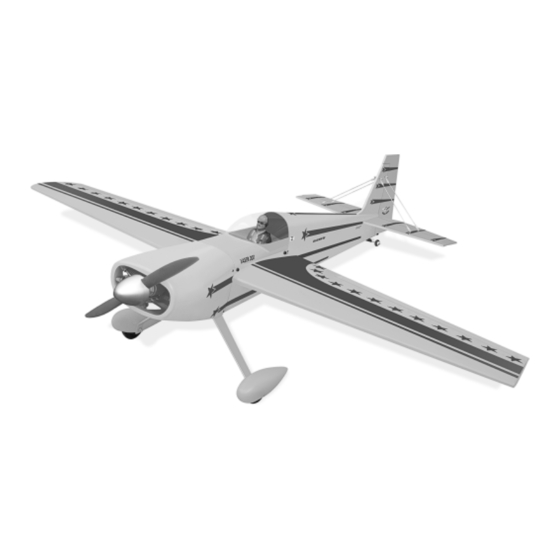
LASER 200
Hand-made Almost Ready to Fly R/C Model Aircraft
SPECIFICATIONS:
WING SPAN ----------------------------------------175CM -------------------------------- 68.75 in.
WING AREA ------------------------------------------4746CM2 --------------------------735.6 Sq.in.
WEIGHT
---------------------------------------4.1 - 5KG ---------------------- 9.02lb - 11lb.
ENGINE SIZE -------------------------------------.91 - 1.20 ---------------------------- 2 stroke.
-------------------------------------1.20 - 1.50 ---------------------------- 4 stroke.
RECOMMENDED R/C --------------------------- 4 CHANNEL MINIMUM WITH 6 SERVOS.
FLYING SKILL LEVEL ----------------------------------------ADVANCED / INTERMEDIATE.
LENGTH -------------------------------------------161CM ----------------------------------63.4in.
Kit features
•
Ready-made-minimal assembly & finishing required.
•
Ready-covered covering.
•
Comprehensive hardware pack including wheels, tank, spats,undercarriage.
•
Photo-illustrated step-by-step Assembly Manual.
Made in Vietnam.
ASSEMBLY MANUAL
Advertisement
Table of Contents

Related Manuals for Seagull Models Laser 200


Summary of Contents for Seagull Models Laser 200
-
Page 1: Specifications
LASER 200 Hand-made Almost Ready to Fly R/C Model Aircraft ASSEMBLY MANUAL SPECIFICATIONS: WING SPAN ----------------------------------------175CM -------------------------------- 68.75 in. WING AREA ------------------------------------------4746CM2 --------------------------735.6 Sq.in. WEIGHT ---------------------------------------4.1 - 5KG ---------------------- 9.02lb - 11lb. ENGINE SIZE -------------------------------------.91 - 1.20 ---------------------------- 2 stroke. -
Page 2: Fuselage Assembly
Flying the LASER 200 is simply a joy. This instruction manual is designed to help you build a great flying aeroplane. Please read this manual thoroughly before starting assembly of your LASER 200 . Use the parts listing below to identify all parts. - Page 3 This will ensure proper as- sembly as the LASER 200 is made from natural materials and minor ad- justments may have to be made. The paint and plastic parts used in this kit are fuel proof.
-
Page 4: Hinging The Ailerons
LASER 200 Instruction Manual HINGING THE AILERONS. Note: The control surfaces, including the ailerons, elevators, and rudder, are prehinged with hinges installed, but the hinges are not glued in place. It is imperative that you properly adhere the hinges in place per the steps that follow using a high-quality thin C/A glue. -
Page 5: Installing The Aileron Servos
LASER 200 Instruction Manual 6) Using C/A remover/debonder and a Using a small weight ( Weighted fuel pick-up ) and thread, feed the string through paper towel, remove any excess C/A glue that works well the wing as indicated. may have accumulated on the wing or in the aileron hinge area. -
Page 6: Installing The Aileron Linkage
LASER 200 Instruction Manual Repeat the procedure for the other wing 2MM x 30mm. half. 3MM x 30mm. M3 lock nut. AILERON LINKAGE. INSTALLING THE AILERON LINKAGE. C/A glue attach. 1) Using a ruler & pen to draw a straight Control Horn. - Page 7 LASER 200 Instruction Manual M2 lock nut. Snap keepper. Mark point. Repeat the procedure for the other wing half.
-
Page 8: Engine Mount
LASER 200 Instruction Manual ENGINE MOUNT. FUEL TANK. INSTALLING THE STOPPER ASSEMBLY. 1) Using a modeling knife, carefully cut off the rear portion of one of the 3 nylon tubes leaving 1/2” protruding from the rear of the stopper. This will be the fuel pick up tube. - Page 9 LASER 200 Instruction Manual Carefully use a lighter or heat gun to You should mark which tube is the vent permenently set the angle of the vent tube. and which is the fuel pickup when you attach fuel tubing to the tubes in the stopper.
- Page 10 LASER 200 Instruction Manual 2) Follow diagram below for wheel pant installation: Plywood Washer. Wheel Collar. Axle. Nut. Nut. Wheel. Landing Gear. Wheel Pant. 7mm. lite-plywood block. 14mm. 3) You have to trim each axles and using a toll cutting and cut-off wheel.
-
Page 11: Mounting The Engine
LASER 200 Instruction Manual 4) A drop of C/A glue on the wheel collar Pushrod wire. screws will help keep them from coming lose during operation. Repeat the process for the other wheel. MOUNTING THE ENGINE. 1) Trial fit your engine on the motor mount. -
Page 12: Installing The Main Landing Gear
LASER 200 Instruction Manual Because of the size of the cowl, it may be nec- essary to use a needle valve extension for the high speed needle valve. Make this out of suf- ficient length 1.5mm wire and install it into the 1.5mm wire... -
Page 13: Elevator And Rudder Servo Installation
LASER 200 Instruction Manual ELEVATOR AND RUDDER SERVO INSTALLATION. We recommended to use long ser- vos arm for all servos without throttle servo. Locate and cut out the covering film from the servo holes in both sides of fuselage. INSTALLING THE SPINNER. -
Page 14: Horizontal Stabilizer
LASER 200 Instruction Manual 3) Slide the elevator on the horizontal stabilizer panel until there is only a slight gap. The hinge is now centered on the horizontal C/A glue. stabilizer panel and elevator. Remove the T- pins and snug the elevator against the horizontal stabilizer panel. - Page 15 LASER 200 Instruction Manual Remove covering. 2) Using a modeling knife, carefully re- move the covering at mounting slot of hori- zontal stabilizer ( both side of fuselage). When cutting through the covering to re- move it, cut with only enough pressure to only cut through the covering itself.
-
Page 16: Hinging The Rudder
LASER 200 Instruction Manual HINGING THE RUDDER. VERTICAL STABILIZER INSTALLATION. Hinging the rudder refer to hinging the aileron and elevator. 1) Using a modeling knife, remove the covering from over the precut hinge slot cut into the lower rear portion of the fuselage. This slot accepts the lower rudder hinge. - Page 17 LASER 200 Instruction Manual 6)Deflect the vertical stabilizer and completely saturate each hinge with thin C/A glue. The vertical stabilizer front surface 4) Remove the stabilizer. Using a mod- should lightly contact the fuselage during this eling knife, remove the covering from below procedure.
- Page 18 LASER 200 Instruction Manual 9) When you are sure that everything is Opening up the hole slightly with 2.2mm aligned correctly, mix up a generous amount of screw. 30 Minute Epoxy. Apply a thin layer to the mount- ing slot in the top of the fuselage and to the sides and bottom of the vertical stabilizer mounting area.
- Page 19 LASER 200 Instruction Manual C/A glue attach. Control Horn. 3MM x 30mm. Mounting Screws. 2MM x 20mm. Mounting Plate. 3) Using a 1.5mm drill bit and the control horns as a guide, drill the mounting holes through the elevator halves.
-
Page 20: Pushrod Installation
LASER 200 Instruction Manual PUSHROD INSTALLATION. 1) Elevator pushrods assembly follow pictures below. Control horn. Connector. Pushrod. Metal clevis. 2) Rudder pushrods assembly follow picture below. Connector. Metal clevis. Control horn. Pushrod. Rudder control horn. 3) Connect the elevator and rudder servos to your radio’s receiver and turn on the sys-... -
Page 21: Installing The Receiver
LASER 200 Instruction Manual MOUNTING THE TAIL WHEEL BRACKET. 1) Set the tail wheel assembly in place on the plywood plate. The pivot point of the tail wheel wire should be even with the rudder hinge line and the tail wheel bracket should be centered on the plywood plate. - Page 22 LASER 200 Instruction Manual Attatch the aluminium tube into fuselage. Wing bolts. Insert two wing panels as picture below. Canopy hatch. BALANCING. 1) It is critical that your airplane be bal- anced correctly. Improper balance will cause your plane to lose control and crash. The cen- ter of gravity is located 37MM ( 1.5’’) back from...
-
Page 23: Control Throws
Elevator high rate - 7/8” up -7/8” down 2) Check every bolt and every glue joint Elevator low rate -3/8’ up - 3/8” down in the LASER 200 to ensure that everything is tight and well bonded. Rudder high rate -1 1/4” left and right Rudder low rate - 3/4”...
Need help?
Do you have a question about the Laser 200 and is the answer not in the manual?
Questions and answers