Table of Contents
Advertisement
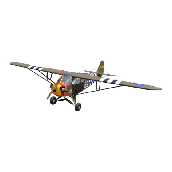
Code : SEA 325
ASSEMBLY MANUAL
Speciications:
Wingspan--------------- 90.0 in (228.6 cm).
Wing area--------------- 1182.3 sq.ins (76.3 sq.dm).
Weight------------------- 13.2 lbs (6.0 kg).
Length------------------- 56.8 in (144.2 cm).
Engine/Motor size----- 20cc gasoline.
Radio--------------------- 4 channels with 5 servos.
1
Advertisement
Table of Contents

Related Manuals for Seagull Models L-4 Grasshopper 90 inches


Summary of Contents for Seagull Models L-4 Grasshopper 90 inches
- Page 1 Code : SEA 325 ASSEMBLY MANUAL Speciications: Wingspan--------------- 90.0 in (228.6 cm). Wing area--------------- 1182.3 sq.ins (76.3 sq.dm). Weight------------------- 13.2 lbs (6.0 kg). Length------------------- 56.8 in (144.2 cm). Engine/Motor size----- 20cc gasoline. Radio--------------------- 4 channels with 5 servos.
- Page 2 Instruction Manual. L-4 Grasshopper 90 inches INTRODUCTION L-4 Grasshopper 90 inches hank you for choosing the ARTF by SG MODELS . he L-4 Grasshopper 90 inches was designed with the intermediate/advanced sport lyer in mind. It is a semi scale airplane which is easy to ly and quick to assemble. he air- frame is conventionally built using balsa, plywood to make it stronger than the aver- age ARTF, yet the design allows the aeroplane to be kept light.
- Page 3 KIT CONTENTS HINGING THE AILERON L-4 Grasshopper 90 inches SEA325 Note : he control surfaces, including the ailer- 1. Fuselage ons, elevators, and rudder, are prehinged with 2. Wing set (2) hinges installed, but the hinges are not glued in 3.
- Page 4 Instruction Manual. L-4 Grasshopper 90 inches Delect the aileron and completely saturate each hinge with thin C/A glue. he ailerons front surface should lightly contact the wing during this procedure. Ideally, when the hinges are glued in place, a 1/64” gap or less will be maintained throughout the lengh of the aileron to the wing panel hinge line.
- Page 5 Fiberglass control horn Minimum servo spec. Torque : 80 oz-in (5.8 kg-cm) @ 4.8V; 100 oz-in (7.2 kg-cm) @ 6.0V Because the size of servos difer, you may need to adjust the size of the precut opening in the mount. he notch in the sides of the mount allow the servo lead to Epoxy pass through.
- Page 6 Instruction Manual. L-4 Grasshopper 90 inches Apply 1-2 drops of thin C/A to each Use drill bit in a pin vise to drill the of the mounting tabs. Allow the C/A to mouting holes in the blocks. cure without using accelerator.
- Page 7 AILERON PUSHROD INSTALLATION Please see below pictures. 105mm Set the aileron hatch in place and use a Phillips screw driver to install it with four wood screws. 3x10mm INSTALLING THE FUSELAGE SERVOS Because the size of servos difer, you may need to adjust the size of the precut opening in the mount.
- Page 8 Instruction Manual. L-4 Grasshopper 90 inches INSTALLING THE RECEIVER SWITCH Elevator servo Install the switch into the precut hole in the side, in the fuselage. 3/32” Hole. Rudder servo hrottle servo Trim and cut Elevator servo arm Switch Rudder servo arm...
- Page 9 Switch INSTALLING LANDING GEAR Locate items necessary to install Sprin Landing Gear. 1\4 inch...
- Page 10 Instruction Manual. L-4 Grasshopper 90 inches Epoxy...
- Page 11 Epoxy Epoxy...
- Page 12 Instruction Manual. L-4 Grasshopper 90 inches 3x15mm 3x15mm...
- Page 13 3x15mm 3x15mm 3x12mm...
- Page 14 Instruction Manual. L-4 Grasshopper 90 inches Using a modeling knife, cut one length of silicon fuel line. Connect one end of the line to the weighted fuel pick up and the other end to the nylon pick up tube. 4x5mm Fuel pick up tube.
- Page 15 With the stopper assembly in place, the weighted pick-up should rest away from the rear of the tank and move freely inside the tank. he top of the vent tube should rest just below the top of the tank. It should not touch the top of the tank.
- Page 16 Instruction Manual. L-4 Grasshopper 90 inches ENGINE MOUNT INSTALLATION MOUNTING THE ENGINE Locate the items necessary to install the Position the engine with the drive washer engine mount included with your model. (140mm) forward of the iewallas shown. 140mm Use four 4x30mm head bolts and four...
- Page 17 Reinstall the servo horn by sliding the connector over the pushrod wire. Cent- er the throttle stick and trim and install the servo horn perpendiular to the servo center line. Machine screw M4x30mm Move the throttle stick to the closed po- sition and move the carburetor to closed.
- Page 18 Instruction Manual. L-4 Grasshopper 90 inches...
- Page 20 Instruction Manual. L-4 Grasshopper 90 inches Epoxy Tape the cowl to the fuselage using low- tack tape. Use a drill and drill bit to drill the holes for the cowl mounting screws. Make sure the cowl position is correct before drill-...
- Page 21 3x10mm Because of the size of the cowl, it may be nec- essary to use a needle valve extension for the high speed needle valve. Make this out of suf- icient length 1.5mm wire and install it into the end of the needle valve. Secure the wire in place by tightening the set screw in the side of the needle valve.
- Page 22 Instruction Manual. L-4 Grasshopper 90 inches ELECTRIC POWER CONVERSION Locate the items neccessary to install the electric power conversion included with your model. M4x25mm and washers. Attach the motor to the front of the electric motor box using four 4mm blind nut, four M4x25mm hex head bolts to se- cure the motor.
- Page 23 Attach the speed control to the side of the motor box using two-sided tape and tie wraps. Connect the appropriate leads from the speed control to the mo- tor. Make sure the leads will not interfere Blind nut. with the operation of the motor. Speed control M4x20mm Battery...
- Page 24 Instruction Manual. L-4 Grasshopper 90 inches he propeller should not touch any part of the spinner cone. If it does, use a sharp modeling knife and carefully trim away the spinner cone where the propel- ler comes in contact with it.
- Page 25 Check all alignments. Mark the outline Fit the joiner wire into the elevator of the fuselage on the top and bottom of halves. the stabilizer. he elevator joiner wire must be flush with the leading edge of the elevator as Use a ruler and carefully cut the cover- shown.
- Page 26 Instruction Manual. L-4 Grasshopper 90 inches * he slot for the elevator horn will be lo- Once the alignment of the stabilizer cated on the bottom right of the fuselage has been verified, use a paper towel and when the elevators are installed.
- Page 27 he clear packing material is used to prevent accidentally gluing the elevator or joiner wire to the stabilizer. Fit the elevator so the leading edge fits tightly against the trailing edge of the sta- bilizer. Mix a small amount of 15-minute epoxy. Use a toothpick to apply epoxy to the joiner wire.
- Page 28 Instruction Manual. L-4 Grasshopper 90 inches Fit the elevators back into position. Re- move the T-pins and slide the elevators tightly against the stabilizer. Use a paper Epoxy towel and isopropyl alcohol to remove any excess epoxy before it begins to cure.
- Page 29 Flex the control surface through its range of motion a few times to break-in the hinges. his will reduce the initial- load on the servo when the surface is first actuated. Once the epoxy fully cures, apply thin CA to both sides of each hinge. Once the CA cures, gently pull on the fixed sur- face and control surface to make sure the hinges are glued securely.
- Page 30 Instruction Manual. L-4 Grasshopper 90 inches Epoxy ELEVATOR PUSHROD INSTALLATION Install the elevator control horn using the same method as with the aileron con- trol horns. Position the elevator control horn on the both side of elevator. Elevator control horn...
- Page 31 Elevator pushrod M2 clevis 790mm Fuel tubing Hex nut RUDDER PUSHROD INSTALLATION Repeat steps as same as steps done for elevator. MOUNTING THE TAIL WHEEL Locate items necessary to install tail wheel.
- Page 32 Instruction Manual. L-4 Grasshopper 90 inches C/A glue. M3x15mm 3x10mm...
- Page 33 INSTALL BRACING WIRE AND METAL BRACKET AT THE TAIL TOP VIEW. 3x15mm...
- Page 34 Instruction Manual. L-4 Grasshopper 90 inches 3x15mm...
- Page 35 BOTTOM VIEW...
- Page 36 Instruction Manual. L-4 Grasshopper 90 inches SIDE DOOR INSTALLTION Please see below pictures. 2x6mm...
- Page 37 INSTALL WINDSHIELD OF THE SIDE DOOR Please see below pictures. Epoxy...
- Page 38 Instruction Manual. L-4 Grasshopper 90 inches Epoxy Epoxy...
- Page 39 INSTALLATION PILOT AND CANOPY Locate items necessary to install pilot and canopy. Epoxy Epoxy Epoxy...
- Page 40 Instruction Manual. L-4 Grasshopper 90 inches Epoxy INSTALLING BATTERIES AND LEDS Please see below pictures. INSTALLING NEEDED ANTEN Parts requirement.See pictures below. Lamp voltage 12v, use appropriate bat- tery.
- Page 41 INSTALLING BATTERY - RECEIVER Plug the servos leads and the switch lead into the receiver. Plug the battery pack lead into the switch also. Wrap the receiver and battery pack in the protective foam rubber to protect them from vibration. Two batteries.
- Page 42 Instruction Manual. L-4 Grasshopper 90 inches 3x15mm 3x10mm INSTALLATION WING STRUTS Loacte the items for this section of the manual.
- Page 43 Diagonal brace M3x15mm Socket Head Cap Screw Nylon washer Nylon washer M3 locknut Front...
- Page 44 Instruction Manual. L-4 Grasshopper 90 inches 100mm 86mm...
- Page 45 Wing bolt 3x12mm ATTACHMENT WING - FUSELAGE Attach the aluminium tube into fuselage. Wing tube...
- Page 46 Instruction Manual. L-4 Grasshopper 90 inches APPLY THE DECALS If all the decals are precut and ready to stick. Please be certain the model is clean and free from oily ingerprints and dust. Position decal on the model where de- sired, using the photos on the box and aid in their location.
- Page 47 With the model inverted, place your in- CONTROL THROWS gers on the masking tape and carefully lit the plane. his is the point at which Ailerons: Rudder: your model should balance for your irst High Rate : High Rate : lights.
- Page 48 Instruction Manual. L-4 Grasshopper 90 inches 20-30mm 20-30mm 30-40mm Fuselage 30-40mm 20-30mm Wing 20-30mm...
- Page 49 A) Plug in your radio system per the 2) Check every bolt and every glue manufacturer’s instructions and turn eve- L-4 Grasshopper 90 inches rything on. joint in the to ensure that everything is tight and well bonded.
- Page 50 Instruction Manual. L-4 Grasshopper 90 inches If you have any queries, or are interested in our products, please feel free to contact us Factory : 12/101A - Hamlet 4 - Le Van Khuong Street - Dong hanh Ward - Hoc Mon District - Ho Chi Minh City - Viet Nam.
Need help?
Do you have a question about the L-4 Grasshopper 90 inches and is the answer not in the manual?
Questions and answers