Table of Contents
Advertisement
Quick Links
Advertisement
Table of Contents

Related Manuals for Icom FR3000 02


Summary of Contents for Icom FR3000 02
- Page 1 INSTRUCTION MANUAL VHF FM REPEATER iFR3000 UHF FM REPEATER iFR4000...
-
Page 2: Explicit Definitions
Icom, Icom Inc. and the logo are registered trademarks peratures below –30°C (–22°F) or above +60°C of Icom Incorporated (Japan) in the United states, the United (+140°F). Be aware that temperatures on a vehicle’s Kingdom, Germany, France, Spain, Russia and/or other coun- dashboard can exceed 80°C (+176°F), resulting in per-... -
Page 3: Declaration Of Conformity
This equipment complies with the Federal Communi- Should you experience trouble with this equipment, cations Commission (FCC) rules and regulations gov- please contact: ICOM America, Technical Support at erning telephone equipment and the Technical 425-454-7619 for repair or warranty information. If the... -
Page 4: Forward
FR3000/FR4000 is designed FR3000/FR4000 series VHF/UHF FM REPEATER and built with Icom’s state of the art technology and craftsmanship. With proper care, this product should [AC120V version] q AC power cable (OPC-510) ……………………… 1 provide you years of trouble-free operation. -
Page 5: Table Of Contents
TABLE OF CONTENTS IMPORTANT ............i 3 OPTIONAL UNIT INSTALLATION ... 11 I Opening the repeater’s case ....... 11 EXPLICIT DEFINITIONS ......... i PRECAUTION ............i I Voice scrambler unit installation ....11 DECLARATION OF CONFORMITY ....... ii 4 OPERATION ..........12 FORWARD ............. -
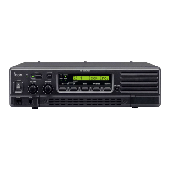
Page 6: Panel Description
PANEL DESCRIPTION I Front panel Function display (p. 2) q POWER SWITCH [POWER] i MODE SELECT SWITCH [RPT/BASE] Toggles to turn the repeater power ON or OFF. Toggles the repeater or base operating mode when pushed. w MICROPHONE/SPEAKER CONNECTOR [MIC/SP] •... -
Page 7: I Rear Panel
PANEL DESCRIPTION !6 ANI CLEAR SWITCH [ANI CLR] D D Function display Push for 1 sec. to clear the received ANI ID indica- tion on the display and returns to original indication. 32HH@HICOMHINC. NOTE: This switch is no function available for some versions. -
Page 8: D Remote Connector
PANEL DESCRIPTION D Remote connector Pin No. Pin Name Description Specification Input terminals to transmit the repeater in rela- –PTT High voltage=PTT ON (transmits) tion to the external equipment. An opto-isolator Hi-Z=PTT OFF is provided to facilitate PTT signals. +PTT Output terminal for AF signals from the AF de- –AFOUT Output impedance: 600 Ω... - Page 9 PANEL DESCRIPTION Accessory connector (continued) Pin No. Pin Name Description Specification M/S OUT Output terminal for master/slave signal. Open collector=OFF, 0V=ON Input terminal for selecting memory channel. +5 V pull up, Active=L Input terminal for selecting memory channel. +5 V pull up, Active=L Input terminal for selecting memory channel.
-
Page 10: Installation And Connections
INSTALLATION AND CONNECTIONS I Unpacking I Duplexer After unpacking, immediately report any damage to the A duplexer is separately required when only one an- delivering carrier or dealer. Keep the shipping cartons. tenna is used for both transmitting and receiving. Se- lect a duplexer according to the transmitting and re- For a description and a diagram of accessory equip- ceiving frequencies. -
Page 11: I Required Connections
CAUTION: DO NOT short pin 1 to ground as this can damage the internal 9 V regulator. DC voltage is applied to pin 1 for microphone operation. Take care when using a non-Icom microphone. [DC POWER INPUT TERMINAL] (p. 8) + red... -
Page 12: I Advanced Connections
INSTALLATION AND CONNECTIONS I Advanced connections LINE CONNECTOR (Front panel view) q NC (No connection) w L1 input/output e L2 input/output r NC (No connection) * This illustration is example only. Telephone connector type is different for some countries. EXTERNAL SPEAKER Use a 4 Ω... -
Page 13: I Power
INSTALLATION AND CONNECTIONS I Power I Mounting the repeater D Using the optional MB-78 Make sure the [POWER] switch is turned OFF when connecting an AC power cable and a backup battery An optional MB-78 INCH RACK MOUNT BRACKET (emergency power supply). available for mounting the repeater into a 19 inch rack. - Page 14 INSTALLATION AND CONNECTIONS • Top side installation q Remove the 1 screw (M4 × 8) from both side of the t Remove the 2 screws (M4 × 8) from both side of MB-78. the side panel (front-end). w Remove the handles from bottom bar. And turn the y Attach the MB-78 to the top side of the repeater.
-
Page 15: D Using The Optional Mb-77
INSTALLATION AND CONNECTIONS D Using the optional MB-77 • Mount the MB-77 securely with the 12 supplied An optional MB-77 is available WALL MOUNT BRACKET screws (M6 × 30) to a surface which is more than 50 for mounting the repeater to a flat surface. mm thick and can support more than 20 kg. -
Page 16: Optional Unit Installation
OPTIONAL UNIT INSTALLATION I Opening the repeater’s case Follow the case and cover opening procedures shown here when an optional unit is installed or adjust the in- ternal units, etc. CAUTION: DISCONNECT the AC power cable and/or DC power cable from the repeater. Other- wise, there is danger of electric shock and/or equip- ment damage. -
Page 17: Operation
Push [POWER] to turn power ON. w If the repeater is programmed for a power on pass- word by an Icom Dealer, input digit codes directly. • The keys in the table below can be used for password input. -
Page 18: Maintenance
The following chart is designed to help correct prob- If you are unable to locate the cause of a problem or lems which are not equipment malfunctions. solve it through the use of this chart, contact the near- est Icom Dealer or Service Center. PROBLEM POSSIBLE CAUSE SOLUTION REF. -
Page 19: I Fuse Replacement
MAINTENANCE I Fuse replacement R R WARNING: If a fuse blows or the repeater stops functioning, try to DISCONNECT the AC power find the source of the problem, and replace the dam- cable and/or DC power cable from the repeater. aged fuse with a new, rated fuse. -
Page 20: Specifications And Options
SPECIFICATIONS AND OPTIONS I Specifications Specifications are measured in accordance with EIA/TIA-603. D D IC-FR3000 Receiver General • Receive system : Double conversion • Frequency coverage : 150.000–174.000 MHz* superheterodyne system 148.000–172.000 MHz* * Depends on version • Sensitivity (12 dB SINAD) : 0.25 µV typical •... -
Page 21: I Options
SPECIFICATION AND OPTIONS I Options Transmitter • RF output power : 50 W • Modulation system : Variable reactance frequency • MB-77 WALL MOUNT BRACKET (p. 10) modulation system For mounting the repeater to a wall. • Max. frequency deviation : ±5.0 kHz (Wide), ±2.5 kHz (Narrow) •... - Page 22 MEMO...
- Page 23 MEMO...
- Page 24 Count on us! American Communication Systems Discover the Power of Communications ™ http://www.ameradio.com TO ORDER – VISIT A-6228H-1EX-w Printed in Japan 1-1-32 Kamiminami, Hirano-ku, Osaka 547-0003 Japan © 2003 Icom Inc.
Need help?
Do you have a question about the FR3000 02 and is the answer not in the manual?
Questions and answers