Table of Contents
Advertisement
Quick Links
Advertisement
Table of Contents
Troubleshooting

Related Manuals for Symbol VRC 89XX


Summary of Contents for Symbol VRC 89XX
- Page 1 VRC 89XX Radio Terminal Product Reference Guide ® for Embedded Windows CE .NET...
- Page 3 VRC 89XX Radio Terminal Product Reference Guide ® for Embedded Windows CE .NET 72-65924-01 Revision A December 2003...
- Page 4 The software is provided strictly on an “as is” basis. All software, including firmware, furnished to the user is on a licensed basis. Symbol grants to the user a non-transferable and non-exclusive license to use each software or firmware program delivered hereunder (licensed program).
-
Page 5: Table Of Contents
Symbol Support Center ........ - Page 6 Powering on the VRC 89XX ........
- Page 7 Contents Status Tabs ..............5-9 Signal Tab .
- Page 8 ® VRC 89XX Radio Terminal Product Reference Guide for Embedded Windows CE .NET...
-
Page 9: About This Guide
About This Guide Introduction ® The VRC 89XX Radio Terminal Product Reference Guide for Embedded Windows CE .NET provides general instructions for setting up, initializing, operating, troubleshooting and maintaining the VRC 89XX Radio Terminal. Chapter Descriptions • Chapter 1, Getting Started, describes how to set up the terminal. -
Page 10: Notational Conventions
Call the Support Center from a phone near the scanning equipment so that the service person can try to talk you through your problem. If the equipment is found to be working properly and the problem is symbol readability, the Support Center will request samples of your bar codes for analysis at our plant. -
Page 11: Symbol Support Center
About This Guide Note: Symbol Technologies is not responsible for any damages incurred during shipment if the approved shipping container is not used. Shipping the units improperly can possibly void the warranty. If the original shipping container was not kept, contact Symbol to have another sent to you. - Page 12 ® VRC 89XX Radio Terminal Product Reference Guide for Embedded Windows CE .NET Finland/Suomi France Oy Symbol Technologies Symbol Technologies France Kaupintie 8 A 6 Centre d'Affaire d'Antony FIN-00440 Helsinki, Finland 3 Rue de la Renaissance 92184 Antony Cedex, France...
- Page 13 Tel: Switchboard: 08 445 29 00 (domestic) Tel: Call Center: +46 8 445 29 29 (international) Support E-Mail: Sweden.Support@se.symbol.com If you purchased your Symbol product from a Symbol Business Partner, contact that Business Partner for service. For the latest version of this guide go to:http://www.symbol.com/manuals.
- Page 14 ® VRC 89XX Radio Terminal Product Reference Guide for Embedded Windows CE .NET...
-
Page 15: Chapter 1. Getting Started
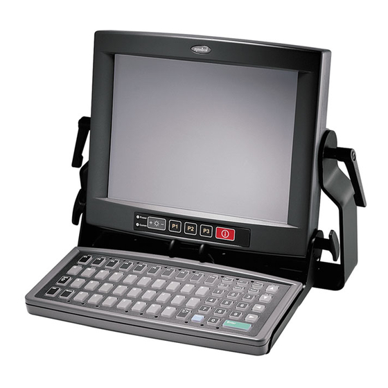
Chapter 1 Getting Started Introduction The VRC 89XX Radio Terminal is a rugged, vehicle-mounted terminal designed to run logistics and warehousing management systems. The terminal is configured as either an RF terminal, providing real-time Wireless Local Area Network (WLAN) communications, or ®... -
Page 16: Unpacking The Terminal
Carefully remove all protective material from around the terminal and save the shipping container for later storage and shipping. Verify that you received all equipment listed on the packing slip and inspect the equipment for damage. If there are any items missing or damaged, contact the Symbol Support Center immediately (see page ix). -
Page 17: Accessories And Peripherals
Caps Figure 1-2. Bottom View Accessories and Peripherals The VRC 89XX comes with an installation kit which includes all necessary connectors and cables. See Installation Kit Contents on page 2-4 for a list of items. Optional Accessories You can order these optional accessories from Symbol: •... -
Page 18: Radio Cards
Stromversorgung in den Ausgabe: 12V dc und minimum 9A (p/n 50-14001-004). Die Stromversorgung ist bescheinigt nach EN60950 mit SELV Ausgaben. Radio Cards VRC 89XX terminals include an internal radio card for use with Symbol Spectrum24 networks. Contact Symbol Technologies for more information on radio cards. -
Page 19: Chapter 2. Installing The Terminal
Do not install the terminal in a location that will affect vehicle safety, drive- ability, or visibility. ARNING The VRC 89XX is intended for use on vehicles primarily operating indoors, or for fixed indoor installation. The VRC 89XX should not be installed in fixed outdoor locations, or on a vehicle primarily operating outdoors, unless additional environmental protection is provided. -
Page 20: Installing Your Terminal
® VRC 89XX Radio Terminal Product Reference Guide for Embedded Windows CE .NET Note: The terminal and bracket must be firmly secured to a surface that can support the terminal’s weight. Table 2-1 on page 2-4 lists the parts in the installation kit included with your terminal. -
Page 21: Routing Electrical Cables
Installing the Terminal Routing Electrical Cables • Establish a neat route for the cable, staying clear of moving parts or hot surfaces wherever possible. • Fix the cable to existing cable runs inside the vehicle using cable ties (item 4, Table 2-1), but make sure they are away from any moving or hot surfaces. -
Page 22: Installation Kit Contents
® VRC 89XX Radio Terminal Product Reference Guide for Embedded Windows CE .NET Installation Kit Contents Table 2-1 lists the parts included with your terminal. Table 2-1. Installation Kit of Parts Item Description Quantity VRC 7900/8900 installation power cable VRC 89XX Radio Terminal Quick Reference Guide for ®... -
Page 23: Installing The Terminal
FUSE - 10A max FUSE - 5A max 12-24V FILTER BOX FUSE - 2A max IGNITION SWITCH EARTH POINT (AS VRC 89XX VRC7900 CLOSE AS POSSIBLE TO THE IGNITION SWITCH) Figure 2-1. Installation of 12-24V Gasoline, Diesel, or Propane Vehicles... - Page 24 ® VRC 89XX Radio Terminal Product Reference Guide for Embedded Windows CE .NET Electric Vehicles Up to 60V Refer to Table 2-1 for item descriptions. Refer to Figure 2-2 for installation. • All power wiring must use the cable specified in item 1.
-
Page 25: Providing Power To The Terminal
For example, connect the power cable to the battery first, then connect it to the terminal. Follow the instructions below to connect power to the terminal using the filter box. VRC 89XX Series Filter Box VRC7900 Series... - Page 26 ® VRC 89XX Radio Terminal Product Reference Guide for Embedded Windows CE .NET Table 2-2. Filter Box Connections Filter Box Connections Wire 4-pin Amphenol connector as follows: Pin 1 or 4 Positive (red and green joined together) Pin 2 or 3...
-
Page 27: Connecting Ac Power To Your Terminal
Connecting AC Power to Your Terminal You can power your terminal away from a vehicle using an AC universal power supply, an AC line cable, and a DC power cable available from Symbol Technologies. To provide power from an AC source: 1. -
Page 28: Connecting The Filtered Dc Power Cable For Electric Trucks
® VRC 89XX Radio Terminal Product Reference Guide for Embedded Windows CE .NET Connecting the Filtered DC Power Cable for Electric Trucks This section describes how to connect and use the filtered DC power cable to provide power to the terminal when mounted on an electric truck. - Page 29 Installing the Terminal 6. Place a fuse holder in-line of the brown and blue wire approximately 4 inches from the cable end, as shown below. Fuse Terminal Ends Fuse Holder Spring Fuse Fuse Holder Solder the fuse terminal ends to the wire to ensure a proper electrical connection. 7.
-
Page 30: Installation And The Internal Battery
® VRC 89XX Radio Terminal Product Reference Guide for Embedded Windows CE .NET Caution Use extreme care when routing and securing this cable from the terminal to the vehicle power source. Hazards associated with improper wiring can be severe. To avoid unintentional contact between the wire and any sharp edges, use proper bushings and clamping where the cable passes through openings. -
Page 31: The Optional Keyboard
Installing the Terminal The Optional Keyboard The keyboard bracket assembly contains the following items: • Optional keyboard • Keyboard bracket • 4 M4 screws and washers • Knobs • Adjustment mechanism • Side plates • Bracket knobs • 5 button-head screws •... - Page 32 ® VRC 89XX Radio Terminal Product Reference Guide for Embedded Windows CE .NET 2. Secure the adjustment mechanism to the bottom of the display using the 5 button- head screws. Ensure the adjustment levers face forward. Levers Side Plate Adjustment Mechanism Figure 2-6.
-
Page 33: Adjusting The Keyboard
Installing the Terminal 6. Plug the keyboard cable into the Keyboard port on the VRC 89XX. Keyboard Port Adjusting the Keyboard To adjust the keyboard, loosen the locking knobs, squeeze the adjustment levers, then move the keyboard to the desired position. Tighten the locking knobs. - Page 34 ® VRC 89XX Radio Terminal Product Reference Guide for Embedded Windows CE .NET 2-16...
-
Page 35: Chapter 3. Software Installation On The Development Pc
Chapter 3 Software Installation on the Development PC Introduction To develop applications for your terminal, you will require additional tools for your development environment (see appropriate sections below). If you are developing multiple types of applications then you may need to install all of the utilities that are compatible with each other. -
Page 36: Developing Applications
® VRC 89XX Radio Terminal Product Reference Guide for Embedded Windows CE .NET ® ® • Adobe Acrobat v 4.0 or greater (recommended). This can be downloaded from http://www.adobe.com/. Developing Applications Software Requirements ® ® • Microsoft Visual Studio .NET 2003, for developing C# (C sharp) or Visual Basic .NET applications... -
Page 37: Chapter 4. Operating The Terminal
Introduction This chapter describes how to power, initialize, and operate the terminal. Powering on the VRC 89XX While the terminal’s processor and display are off, programs or data in the system's memory are retained. Power-up restores the display, and processing continues from where it was before power-down. -
Page 38: Booting The Terminal
® VRC 89XX Radio Terminal Product Reference Guide for Embedded Windows CE .NET The network configuration screen displays. If desired, configure the terminal for wireless communication (refer to Chapter 5, Spectrum24 Network Configuration). Note: The network configuration screen appears the first time you start the terminal after power is removed, but not on subsequent warm or cold boots. -
Page 39: Performing A Cold Boot
Operating the Terminal Performing a Cold Boot A cold boot restarts the terminal. In the Windows CE .NET environment, the working registry is replaced by the latest saved copy of the registry. All information in DRAM is discarded (data in Flash is maintained). There are two ways to perform a cold boot: •... -
Page 40: Programmable ("P") Keys
® VRC 89XX Radio Terminal Product Reference Guide for Embedded Windows CE .NET Programmable (“P”) Keys The programmable keys on the membrane panel (P1, P2, P3) can be set to perform certain functions, such as printing, toggling the virtual keyboard, or running a frequently used key sequence. -
Page 41: Using The Keyboard
Operating the Terminal 4. Select the function you’d like the P key to perform from the Action drop-down menu. Figure 4-4. Programmable Keys Screen, Action Drop-Down Menu 5. Tap OK. Using the Keyboard The terminal has an optional QWERTY keyboard. Refer to Figure 4-5 Table 4-2 for a... - Page 42 ® VRC 89XX Radio Terminal Product Reference Guide for Embedded Windows CE .NET Figure 4-5. VRC 89XX Keyboard The following table describes the general functions of the keys. Table 4-3 contains the specific keyboard mappings. Table 4-2. Key Descriptions Description Shift, Ctrl, Alt Use in conjunction with other keys.
- Page 43 Operating the Terminal Table 4-3. Keyboard Mappings VRC 89XX Key Scan Code Virtual Key Func + (Unicode) Shift + (Unicode) > Shell lock < ¬ £ “...
- Page 44 ® VRC 89XX Radio Terminal Product Reference Guide for Embedded Windows CE .NET Table 4-3. Keyboard Mappings (Continued) VRC 89XX Key Scan Code Virtual Key Func + (Unicode) Shift + (Unicode) & VK_ESCAPE VK_HOME VK_HOME VK_UP VK_PRIOR VK_PRIOR DOWN VK_DOWN...
-
Page 45: Locking The Desktop
You can lock the desktop of the VRC 89XX to hide icons that contain configuration information such as terminal and network settings. When you lock the desktop, only the working applications display. If you don’t have the optional keyboard, use the virtual keyboard on the VRC 89XX to perform the following key sequences. •... - Page 46 ® VRC 89XX Radio Terminal Product Reference Guide for Embedded Windows CE .NET 3. Tap Settings, then Control Panel. The Control Panel screen displays. Figure 4-6. Control Panel Screen 4. Double tap the Stylus icon. The Stylus Properties screen displays.
-
Page 47: Calibrating Using The Keyboard
Repeat as the target moves around the screen. 7. Tap the screen to accept the new calibration. Note: If the digitizer fails to respond, call the Symbol Support Center for assistance. Calibrating Using the Keyboard... - Page 48 ® VRC 89XX Radio Terminal Product Reference Guide for Embedded Windows CE .NET 3. Press Enter to display the Control Panel screen. Figure 4-9. Control Panel Screen 4. Using the arrow keys, move to the Stylus icon and press Enter. The Stylus Properties screen appears.
- Page 49 Operating the Terminal 5. Using the Tab key (key with double arrows), select the Calibration tab. Figure 4-11. Calibration Tab 6. Using the Tab key again, select the Recalibrate button. 7. Press Space to start the calibration process. The calibration screen appears. Carefully press and briefly hold stylus on the center of the target.
-
Page 50: Adjusting The Brightness
8. As the screen instructs, carefully press and briefly hold the stylus on the center of each target that appears. Repeat as the target moves around the screen. 9. Tap the screen to accept the new calibration. Note: If the digitizer fails to respond, call the Symbol Support Center for assistance. Adjusting the Brightness Press + on the Brightness Control button on the membrane panel to brighten the screen, or - to darken it. -
Page 51: Connecting Accessories
Connect an optional scanner, ActiveSync serial cable, or USB device using the appropriate port on the bottom of the VRC 89XX. All cables are available from Symbol. You may also use the USB port for ActiveSync connection, if the COM2 port is used for another purpose. - Page 52 ® VRC 89XX Radio Terminal Product Reference Guide for Embedded Windows CE .NET 4. Double-tap the Scanner icon. The Scanner-As-Keyboard Properties screen displays. Figure 4-15. Scanner-As-Keyboard Properties Screen - Information Tab 5. Select the desired ComPort tab. a. Select the Enable Scanner-As-Keyboard for this Com Port checkbox to enable the built in keyboard wedge.
- Page 53 Operating the Terminal application handles the scanner serial port, or the COM1 port is used for a device other than a bar code scanner. 6. Select the Common Settings tab. If the Play Control Keys checkbox is selected, character values lower than 20h will be played as Ctrl+X combinations.
-
Page 54: Saving Files And Allocating Memory
® VRC 89XX Radio Terminal Product Reference Guide for Embedded Windows CE .NET Saving Files and Allocating Memory The terminal uses a Flash file system and a DRAM file system to save files, run applications, and allocate memory as necessary. - Page 55 Operating the Terminal To boot up using the default registry in RAM: 1. With the terminal in suspend mode, hold down the P1 + P3 + Suspend buttons. 2. Release only the Suspend button when the terminal powers up. 3. Release P1 + P3 when the Boot Loader menu displays. 4.
- Page 56 ® VRC 89XX Radio Terminal Product Reference Guide for Embedded Windows CE .NET 4-20...
-
Page 57: Chapter 5. Spectrum24 Network Configuration
Spectrum24 Network Configuration Introduction In order to use Symbol’s Spectrum24 wireless LAN on the VRC 89XX terminals, the terminal must be properly configured with the correct ESS ID and other network entries. This chapter describes how to configure your terminal on the Spectrum24 wireless network. -
Page 58: Configuring Your 11 Mbps Terminal
® VRC 89XX Radio Terminal Product Reference Guide for Embedded Windows CE .NET Configuring Your 11 Mbps Terminal To configure the terminal for use on the Spectrum24 wireless network: 1. Tap the NICTT icon located on the bottom of the screen. -
Page 59: Wlan Profiles Tabs
Spectrum24 Network Configuration 5. Once all settings have been configured, tap OK. 6. Tap the NICTT icon located on the bottom of the screen and select Status. The Mobile Companion window opens, consisting of five tabs - Signal, Info, IP Status, Ping and APs. -
Page 60: Encryption Tab
This ensures the mobile computer is using country code information compatible with the country code data used by the associated AP. Select International if using the mobile computer with a non-Symbol AP or a pre AP- 4131 model. Encryption Tab The Encryption tab controls encryption options. - Page 61 Spectrum24 Network Configuration • Use the Algorithm: drop-down list to select an encryption algorithm that matches the security established in your network. The AP and the terminal’s adapter must use the same encryption. • The Open System does not encrypt any of the data packets that travel over the WLAN, meaning the data packets transmitted by terminals or APs are not encrypted.
- Page 62 ® VRC 89XX Radio Terminal Product Reference Guide for Embedded Windows CE .NET • Select Kerberos if your network employs the Kerberos system. Enter the KDC and Realm values. The KDC is located on a server and maintains information about the access points and users it supports, and also permits the transmission and receipt of data once the credentials of the user are verified.
-
Page 63: Ip Configtab
Spectrum24 Network Configuration IP ConfigTab The IP Config tab allows you to adjust IP configuration settings. DHCP Static Figure 5-7. IP Config Tab • Select Dynamic Host Configuration Protocol (DHCP) from the IP Type drop-down list to obtain a leased IP address and network configuration information from a remote server. -
Page 64: Powertab
® VRC 89XX Radio Terminal Product Reference Guide for Embedded Windows CE .NET PowerTab The IP Config tab allows you to set the Radio Transmission Power level and the Power Saving Modes for the terminal profile. Infrastructure Mode Ad Hoc Mode Figure 5-8. -
Page 65: Status Tabs
Spectrum24 Network Configuration very close proximity. Additionally, select minimum Spectrum24 Network Configuration power in instances where little or no radio interference from other devices is anticipated. The Automatic Power Saving Mode switches to Best Network Performance when an AC power supply is detected. If a battery is used, an appropriate setting between Best Network Performance and Acceptable Network Performance is automatically chosen based on a real-time analysis of network usage. -
Page 66: Info Tab
® VRC 89XX Radio Terminal Product Reference Guide for Embedded Windows CE .NET Info Tab The Info tab provides information about the terminal, such as firmware and hardware versions, adapter type, and operating mode. Figure 5-10. Info Tab IP Status Tab The IP Status tab in NICTT provides information about the terminal, such as IP type and IP address, Subnet Mask and Gateway. -
Page 67: Ping Tab
Spectrum24 Network Configuration • Subnet Mask: Most TCP/IP networks use subnets to manage routed IP addresses. This allows the network to connect to the Internet with a single shared network address, e.g., 255.255.255.0. • Default Gateway: Used to forward IP packets to and from a remote destination. See your network administrator for the IP address required for the default gateway. -
Page 68: Aps Tab
® VRC 89XX Radio Terminal Product Reference Guide for Embedded Windows CE .NET 2. Select the size of packets sent from the Size drop-down list. 3. Tap Start Test to begin the continuous ping test. Tap Stop Test to terminate the ping test. -
Page 69: Peers Tab
Spectrum24 Network Configuration • Tap the Refresh button to update the list of the known APs. Peers Tab Use the Peers tab to to display the BSSID or MAC addresses of the other terminals in the network, their operating mode (PSP or CAM), their transmit rate, their supported data rate and the length of time an adapter has been out of the Ad Hoc network. -
Page 70: Options Tab
® VRC 89XX Radio Terminal Product Reference Guide for Embedded Windows CE .NET Options Tab Use the Options tab to enable or disable the suspend wireless network option and system sounds, and set temporary settings. Figure 5-15. Options Tab •... -
Page 71: Chapter 6. Configuring The Terminal
Chapter 6 Configuring the Terminal Introduction This chapter describes the terminal’s Flash partitions and how they are used to specify and load files into the Flash memory of the terminal using ActiveSync. Flash Partitions In addition to the RAM-based storage standard on Windows CE .NET terminals, the VRC 89XX is equipped with a non-volatile Flash-based storage area which can store data (partitions) that cannot be corrupted by a cold boot. -
Page 72: Non-Ffs Partitions
To download the operating system via the serial port, the following equipment is required: • • ActiveSync cable • The VRC8900 CE .NET update program available on the Windows CE .NET v4.1 Software User Upgrade Kit for Symbol VRC 79XX/VRC 89XX Terminals CD or downloadable from Microlise’s website, http://www.microlise.com/VRC8900. - Page 73 Configuring the Terminal Note: The Microlise website is password protected. Use the Windows CE .NET license key information, as it appears on the Microsoft .NET license label on your terminal, to gain access to the website. 1. Connect the ActiveSync cable to the COM1 port on the terminal and an available COM port on the PC.
- Page 74 ® VRC 89XX Radio Terminal Product Reference Guide for Embedded Windows CE .NET Press the P2 button. The following menu appears. VRC8900 BootLoader Boot Ver X.X.XXX Service Menu: - 1 - Download OS 2 - Download Bootcode 3 - Production Tests...
- Page 75 Configuring the Terminal 5. Press the Brightness “-” (minus) button on the switch panel to highlight 2 - Serial. Press the P2 button to select this. 6. Select option 3 (115200) on the VRC8900 to initiate the download.Before pressing P2 to initiate the download setup the PC from step 7. VRC8900 BootLoader Boot Ver X.X.XXX Select Baud: -...
- Page 76 ® VRC 89XX Radio Terminal Product Reference Guide for Embedded Windows CE .NET a. Start the program OSUPDATE.EXE. The following screen appears: Figure 6-6. OSUpdate Screen b. Click Next. Figure 6-7. Download Type c. Select Serial Operating System Update from the Download Type drop-down...
- Page 77 Configuring the Terminal d. Click Next. Figure 6-8. Serial Port Configuration e. Select the Comport that you want to use, this is the comport on you PC/Laptop that you have your serial cable attached to. f. Select the Baud rate that you want to use for the download. This must be the same as the baud that you select from the terminal.
-
Page 78: Downloading The Operating System By Rf Update
CE .NET It takes approximately 30 minutes to download a 20Mb file. 9. When the download is complete a message appears on the VRC 89XX asking if the upload version should replace the existing version. Use the Brightness “+” and Brightness “-”... - Page 79 Configuring the Terminal System for your terminal by ensuring that the Terminal Type displayed on the screen matches your terminal. Figure 6-10. OSUpdate Screen 3. If the screen displays the correct information, click Next.The following screen displays. Figure 6-11. Download Type If the OSUpdate screen displays the incorrect information, click Options to load a different Boot Code and Operating System.
-
Page 80: Setting Up The Terminal And Upgrading The Os
® VRC 89XX Radio Terminal Product Reference Guide for Embedded Windows CE .NET 4. Select RF Update using Wireless LAN Adapter from the Download Type drop-down list. 5. Click Next. OSUpdate will initialize itself and listen for requests from terminals. - Page 81 Configuring the Terminal Figure 6-13. Terminal Information Screen 2. Tap Next. 3. WLANUpdate searches for active OSUpdate Servers that have the right operating system and Boot Code for the terminal and creates a list in the screen, as shown below: Figure 6-14.
- Page 82 ® VRC 89XX Radio Terminal Product Reference Guide for Embedded Windows CE .NET enter the IP address and port number of the host computer running OSUpdate. • Ensure that the ESSID on your terminal is correct for the RF network and ensure the WEP encryption is correct, if applicable.
-
Page 83: Installing Wlanupdate With Activesync
2. Ensure that the latest ActiveSync software is installed on your host computer. If not, it is available on the Windows CE .NET v4.1 Software User Upgrade Kit for Symbol VRC 79XX/VRC 89XX Terminals CD or downloadable from Microsoft’s web site at http://www.microsoft.com. - Page 84 ® VRC 89XX Radio Terminal Product Reference Guide for Embedded Windows CE .NET 3. Launch ActiveSync on the host computer. The Get Connected dialog box displays. Figure 6-19. Get Connected 4. When prompted with the Get Connected dialog box, connect the ActiveSync cable to the appropriate port on the terminal and click Next.
-
Page 85: Downloading Applications
5. Select the No checkbox and click Next. The host computer and the terminal are connected. 6. Locate WLANUpdate on your host computer. It is available on the Windows CE .NET v4.1 Software User Upgrade Kit for Symbol VRC 79XX/VRC 89XX Terminals CD or downloadable from Microlise’s website, http://www.microlise.com/ VRC8900. - Page 86 Transfer files by 'dragging and dropping' or 'copying and pasting' from the PC to the specified location on the terminal. To download an installation file for the desktop PC, which, when unpacked has been compiled for VRC 89XX, the file must first be executed so that it unpacks itself on the desktop PC: 6-16...
- Page 87 Configuring the Terminal a. Select Tools, then Add/Remove Programs. The following screen appears: Figure 6-23. Add/Remove Programs Screen b. To install the application on the terminal, check the box next to the application(s) to be installed. If the Install program into the default installation folder is checked, the application files are transferred to the Windows directory on the terminal.
- Page 88 ® VRC 89XX Radio Terminal Product Reference Guide for Embedded Windows CE .NET Note: If the application, or part of it, is installed in DRAM, it will be lost if the back-up battery is allowed to discharge or a cold boot is performed.
-
Page 89: Chapter 7. Activesync
Chapter 7 ActiveSync Introduction This chapter describes communication between the terminal and a desktop PC using ActiveSync. The minimum desktop PC requirements for ActiveSync are: • Windows 2000, Windows NT4 with Service Pack 3 or later, Windows Me, or Windows 95/98 •... -
Page 90: Performing An Activesync
2. From the Start menu on your VRC 89XX, select Settings, Control Panel. 3. Select the PC Connections icon. 4. Under PC Connection, select change and then select which VRC 89XX port you are using for ActiveSync (COM2 or USB port). - Page 91 8. ActiveSync automatically starts on your desktop computer, and connects to the terminal. If no connection occurs, check the PC Connections setting in the Control Panel on the VRC 89XX. On the PC Connections Properties screen, select the Allow connection with desktop computer when device is attached checkbox.
- Page 92 ® VRC 89XX Radio Terminal Product Reference Guide for Embedded Windows CE .NET...
-
Page 93: Chapter 8. Maintenance And Troubleshooting
Maintenance and Troubleshooting Maintaining the Terminal The terminal is factory-sealed and contains no user-serviceable parts. Only qualified Symbol Service Centers should service the terminal. Refer to Symbol Support Center page ix. Protective caps are attached to the ports on the back of the terminal. Place them over unused ports for protection. -
Page 94: Troubleshooting
® VRC 89XX Radio Terminal Product Reference Guide for Embedded Windows CE .NET Troubleshooting Table 8-1 on page 8-2 covers some common terminal problems and corrective actions to take. Table 8-1. Terminal Problems Symptom Possible Cause Action Terminal does not power on Power switch on back of Turn the power switch on. - Page 95 Application currently running Configure the application to enable disabled the sound. the sound. Faulty speaker. Contact Symbol Support Center. Symbol Support Center on page Missing pixels on the display. Faulty LCD. Contact Symbol Support Center. Symbol Support Center...
- Page 96 ® VRC 89XX Radio Terminal Product Reference Guide for Embedded Windows CE .NET...
-
Page 97: Appendix A Specifications
Appendix A Specifications Environment The VRC 89XX is designed to operate in harsh environments. Table A-1 below summarizes the terminal’s intended operating environment. Table A-1. VRC 89XX Operating Environment Operating Temperature Non-heated version: 0° C to 50° C (32° F to 122° F) Heated version: -30°... - Page 98 ® VRC 89XX Radio Terminal Product Reference Guide for Embedded Windows CE .NET Table A-1. VRC 89XX Operating Environment (Continued) Impact 130 gm (4.6 oz), 31.75 mm (1.25 in.) diameter chrome steel ball dropped from 50 cm (19.6 in.) onto any surface including display Thermal Shock -20°...
-
Page 99: Pin-Outs
Specifications Pin-Outs Table A-2. COM1 Serial Port Pin-Outs Description +12V Rx Data (RS-232) Tx Data (RS-232) Ground Table A-3. COM2 Serial Port Pin-Outs Description Connection Detect (1) This input is used with Connection Detect (2) to automatically detect whether the terminal is connected to another device. - Page 100 ® VRC 89XX Radio Terminal Product Reference Guide for Embedded Windows CE .NET Table A-4. Keyboard Port Pin-Outs Description +12V supply for backlight and heater +5V supply to keyboard logic Ground PS2 clock signal (12.5kHz) PS2 data Table A-5. USB Port Pin-Outs...
-
Page 101: Index
Index Numerics 11 Mbps cables APs ......5-12 performing ActiveSync ... . 7-2 configuring . - Page 102 ® VRC 89XX Radio Terminal Product Reference Guide for Embedded Windows CE .NET saving ......4-18 filter box Non-FFS Partitions .
- Page 103 Index IP config ..... . . 5-10 parts ......1-2 options .
- Page 104 ® VRC 89XX Radio Terminal Product Reference Guide for Embedded Windows CE .NET Index-4...
- Page 105 We’d like to know what you think about this Manual. Please take a moment to fill out this questionnaire and fax this form to: (631) 738-3318, or mail to: Symbol Technologies, Inc. One Symbol Plaza M/S B-4 Holtsville, NY 11742-1300 Attention: Technical Publications Manager IMPORTANT: If you need product support, please call the appropriate customer support number provided.
- Page 108 VRC 89XX Radio Terminal Product Reference Guide ® for Embedded Windows CE .NET 72-65924-01 Revision A — December 2003 Symbol Technologies, Inc. One Symbol Plaza, Holtsville N.Y. 11742-1300...
Need help?
Do you have a question about the VRC 89XX and is the answer not in the manual?
Questions and answers