HP Integrity rx2620 User's & Service Manual
Hp integrity rx2620 server user service guide
Hide thumbs
Also See for Integrity rx2620:
- User's & service manual (169 pages) ,
- Read me first (2 pages) ,
- Service manual (177 pages)

Related Manuals for HP Integrity rx2620


Summary of Contents for HP Integrity rx2620
- Page 1 User Service Guide HP Integrity rx2620 Server Manufacturing Part Number: AD117-9003A First Edition August 2006 © Copyright 2006 Hewlett-Packard Development Company, L.P.
-
Page 2: Legal Notices
The information contained herein is subject to change without notice. The only warranties for HP products and services are set forth in the express warranty statements accompanying such products and services. Nothing herein should be construed as constituting an additional warranty. -
Page 3: Table Of Contents
HP-UX Release Name and Release Identifier ........ - Page 4 Contents 3. Powering Off and Powering On the Server Power States............... . 42 Powering Off the Server.
- Page 5 Operating Systems Supported on HP Integrity Servers ........
- Page 6 Contents Adding Microsoft Windows to the Boot Options List ........159 Booting the Microsoft Windows Operating System .
- Page 7 Table 2. HP-UX 11i Releases ........
- Page 8 Table C-4. HP Integrity rx2620 Drives ........
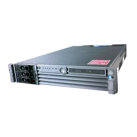
- Page 9 Figure 1-1. HP Integrity rx2620 Server (front view) ....... . .
- Page 10 Figures Figure 4-30. Unlock Processor Module Locking Mechanism ......73 Figure 4-31. Unlocked ZIF Socket Lock ..........74 Figure 4-32.
- Page 11 Figures Figure C-1. EFI Boot Sequence ........... . . 168 Figure C-2.
- Page 12 Figures...
-
Page 13: About This Document
This guide has been updated with: • This document is being updated as part of a processor upgrade to the HP Integrity rx2620 server. Publishing History The publishing history below identifies the edition dates of this manual. Updates are made to this publication on an unscheduled, as needed, basis. -
Page 14: Document Organization
Document Organization This guide is divided into the following chapters. Chapter 1 Introduction Use this chapter to learn about the features and specifications of the HP Integrity rx2620 server. Chapter 2 Controls, Ports, and LEDs Use this chapter to learn about the locations of the external controls, ports, and LEDs on the server. -
Page 15: Hp-Ux Release Name And Release Identifier
Separates items in a list of choices. HP-UX Release Name and Release Identifier Each HP-UX 11i release has an associated release name and release identifier. The uname (1) command with the -r option returns the release identifier. This table shows the releases available for HP-UX 11i. -
Page 16: Hp Encourages Your Comments
Web Site for HP Technical Support: http://us-support2.external.hp.com/ Books about HP-UX Published by Prentice Hall The http://www.hp.com/hpbooks/ Web site lists the HP books that Prentice Hall currently publishes, such as HP-UX books including: • HP-UX 11i System Administration Handbook http://www.hp.com/hpbooks/prentice/ptr_0130600814.html •... -
Page 17: Introduction
Introduction The HP Integrity rx2620 server is a 2-socket server based on the Itanium® processor architecture. The server supports the following operating systems: Microsoft Windows®, HP-UX, Linux®, and OpenVMS. The server is available in either rack-mount or pedestal configurations. The server accommodates up to 12 DIMMs and internal peripherals including disks and a DVD. -
Page 18: Server Overview
Server Overview Server Overview The HP Integrity rx2620 server chassis is a 2U Electronics Industry Association (EIA) enclosure, which mounts in any standard 19 inch EIA rack. All external cabling connects from the rear of the enclosure. With the server installed in the rack, service access is enhanced by the use of chassis slides. It has bays to accommodate 1 + 1 redundant, hot-swappable power supplies, accessible from the front of the product. -
Page 19: Server Dimensions
Weight 17.5 kg (38.6 lb.) • 22.2 kg (49.0 lb.) • Server Components The following components make up the HP Integrity rx2620 server. Processor • 1.4 GHz/12 MB L3 cache dual-core processor • 1.6 GHz/18 MB L3 cache dual-core processor Memory •... -
Page 20: Internal Core I/O
Introduction Server Components Internal Core I/O • Dual channel SCSI U320 interface, two internal 68-pin connectors, one 68-pin external connector • The three internal SCSI drive connectors are the 80-pin type and provide drive electrical hot-plug capability • One internal IDE connector for a slim-line optical device (CD and DVD) External Core I/O •... -
Page 21: Hard Disk Drives
VGA and 2D graphics display • Advanced Features: — Secure Shell (SSH) access — Group actions through the HP Systems Insight Manager (HPSIM) — Directory-based authentication and authorization (LDAP) Hard Disk Drives The following hard disk drives are supported by the rx2620 server: •... -
Page 22: System Board Components
Introduction System Board Components System Board Components This section provides a block diagram of the system board and descriptions of key components (integrated circuits) on the board. Figure 1-4 shows a block diagram of the rx2620 server. Figure 1-4 System Block Diagram Industry Standard DDR1 DIMM DIMM DIMM... -
Page 23: Processor Sockets
The FSB in this product runs at 200 MHz. Data on the FSB are transferred at a double data rate, which allows a peak FSB bandwidth of 6.4 Gb/sec. ZX1 I/O and Memory Controller The HP Integrity rx2620 server supports the following features of the ZX1 I/O and memory controller chip • 8.5 Gb/s peak I/O bandwidth •... -
Page 24: Figure 1-5. Memory Block Diagram
Introduction System Board Components This design does not support any non industry standard DDR DIMMs. Only qualified DIMMs are supported. Figure 1-5 shows a block diagram of the server memory. Figure 1-5 Memory Block Diagram Parallel Termination Resistors for Address and Control Rt=27 ohms Parallel Termination Resistors for DQ[143:72] and associated DQS Rt=27 ohms CS1(0) SA0=1... -
Page 25: I/O Bus Interface
Introduction System Board Components DIMMs are loaded in groups of four, known as a quad. All four DIMMs in a quad must be the same size. Table 1-2 summarizes the memory solutions. Table 1-2 Memory Array Capacities DDR SDRAM Count, Type and Min / Max Memory Size Single DIMM Size Technology... -
Page 26: Processor Dependent Hardware Controller
Introduction System Board Components Processor Dependent Hardware Controller The PDH controller provides these features: • 16-bit PDH bus with reserved address space for — Flash memory — Non-volatile memory — Scratch RAM — Real Time Clock — UARTs — External Registers —... -
Page 27: Baseboard Management Controller
Introduction System Board Components • Decoding logic for PDH devices Baseboard Management Controller The baseboard management controller (BMC) supports the industry-standard Intelligent Platform Management Interface (IPMI) specification. This specification describes the management features that have been built into the system board. These features include: local and remote diagnostics, console support, configuration management, hardware management, and troubleshooting. -
Page 28: Gb System Lans A And B
Support for USB keyboard and mouse • HP-UX supports HP USB keyboard and mouse Data Pathing Information Table 1-3 shows information about data pathing in the HP Integrity rx2620 server. Table 1-3 Data Pathing - Part 1 PCI Slot PCI Card Function... -
Page 29: Table 1-4. Data Pathing - Part 2
Rear bulkhead - Serial port (CLI) A/Console connector. System board Serial Rear bulkhead - Serial B port connector Table 1-4 Data Pathing - Part 2 PCI Slot MAPPER Path HP-UX Path Linux Path Windows Path 0/4/1/0 0/4/1/0 80:01.0 0/3/1/0 0/3/1/0 60:01.0 0/2/1/0 0/2/1/0 40:01.0... -
Page 30: Table 1-5. Data Pathing - Part 3
Introduction System Board Components Table 1-4 Data Pathing - Part 2 (Continued) PCI Slot MAPPER Path HP-UX Path Linux Path Windows Path Core I/O -14 0/0/2/0.0.0 0/0/2/0.0.0 Opt MP -1 0/7/1/0 0/6/1/0 E0:01.0 Opt MP -2 0/7/1/1 0/6/1/1 E0:01.1 Opt MP -3... -
Page 31: Controls, Ports, And Leds
Controls, Ports, and LEDs This chapter describes the controls, ports, and LEDs on the front and rear panels of the HP Integrity rx2620 server. This chapter addresses the following topics: • “Front Panel” on page 32. • “Rear Panel” on page 36. -
Page 32: Front Panel
Front Panel Front Panel The control panel at the front of the HP Integrity rx2620 server provides the controls and indicators commonly used for operation. See Figure 2-1, Figure 2-2, Table 2-1, and Table 2-2 for the location and description of the front panel controls and LEDs. -
Page 33: Table 2-1. Control Panel Leds And Switches
Controls, Ports, and LEDs Front Panel Table 2-1 Control Panel LEDs and Switches (Continued) Name Function System LED The System LED provides information about the system status. When operation is normal, the LED is green. When there is a system warning, the LED is flashing yellow. When there is a system fault, the LED is flashing red. -
Page 34: Hot-Plug Disk Drive Indicators
Power Supply LEDs The HP Integrity rx2620 server is typically delivered with a single power supply (PS 1). An additional power supply (PS 2) may be installed for redundant (n+1) power capability. See Figure 2-4 and Table 2-4 for the location and description of the power supply LEDs. -
Page 35: Table 2-4. Power Supply Led Definitions
Optional Removable Media Drive The HP Integrity rx2620 server is delivered without a removable media drive. Either a DVD or CD-RW/DVD drive may be added. Each of these optional devices has one activity LED. See Figure 2-5 and Table 2-5 for the location and description of the DVD LEDs. -
Page 36: Rear Panel
Rear Panel Rear Panel The HP Integrity rx2620 server rear panel includes communication ports, I/O ports, AC power connectors, and the locator LED/button. Additional LEDs located on the rear panel of the server signal the operational status of the LAN connector of the optional iLO MP. See Figure 2-6 and Table 2-6 for the location and description of the ports and connectors. - Page 37 25-pin female serial data bus connector for the optional iLO MP. This connector (optional) connects to a three-port breakout cable (HP P/N A6144-63001) with individual connectors for Console, Remote and UPS. The Console connector becomes the console connection when the iLO MP is installed.
-
Page 38: Lan Gb A Connector
Controls, Ports, and LEDs Rear Panel LAN Gb A Connector The rear panel 10/100/1000 base-T ethernet LAN Gb A connector has the following status and activity LEDs. See Figure 2-7 and Table 2-7 for the location and description of the LAN Gb A LEDs. Figure 2-7 10/100/1000 base-T ethernet Gb LAN A Connector LEDs Not used... -
Page 39: Lan Gb B Connector
Controls, Ports, and LEDs Rear Panel LAN Gb B Connector The rear panel 10/100/1000 base-T ethernet LAN Gb B connector has the following status and activity LEDs. See Figure 2-8 and Table 2-8 for the location and description of the LAN Gb B LEDs. Figure 2-8 10/100/1000 base-T ethernet Gb LAN B Connector LEDs Speed (Yellow/Green) -
Page 40: Management Processor Lan Leds (Optional)
Controls, Ports, and LEDs Rear Panel Management Processor LAN LEDs (Optional) The LAN port of the optional integrated Lights Out (iLO) Management Processor (MP) uses an RJ-45 type connector. This connector has four LEDs that signal status and activity. The iLO MP is required for Proactive 24 or Critical Service support. -
Page 41: Powering Off And Powering On The Server
Powering Off and Powering On the Server This chapter provides information and procedures for powering off and powering on the server. This chapter addresses the following topics: • “Power States” on page 42. • “Powering Off the Server” on page 42. •... -
Page 42: Power States
Powering Off and Powering On the Server Power States Power States The server has three power states: • Standby power • Full power • Plug the power cord into the appropriate receptacle on the rear of the chassis to achieve the standby power state;... -
Page 43: Powering Off The Server Manually
Powering Off and Powering On the Server Powering On the Server Step 4. Enter PC to use the remote power control command. Step 5. Enter OFF to power off the server, and enter YES when prompted to confirm the action. IMPORTANT The main DC voltage is now removed from the server;... -
Page 44: Powering On The Server Manually
Powering Off and Powering On the Server Powering On the Server Step 6. Start the operating system. See Appendix B, “Booting the Operating System,” on page 147, or your operating system documentation for more information. Powering On the Server Manually If the power restore feature is set to Always On through the iLO MP PR command, the server NOTE may automatically power on to the full power state. -
Page 45: Removing And Replacing Components
Removing and Replacing Components This chapter describes the procedure for removing and replacing the different components in the HP Integrity rx2620 server. This chapter addresses the following topics: • “ESD Information” on page 46 • “Service Tools Required” on page 46 •... -
Page 46: Esd Information
ESD Information Follow the procedures listed below to ensure safe handling of components and to prevent harm to both you and the HP Integrity rx2620 server: • Use an anti-static wrist strap and a grounding mat, such as those included in the Electrically Conductive Field Service Grounding Kit (HP 9300-1155). -
Page 47: Location Of Internal Components And Connectors
Removing and Replacing Components Location of Internal Components and Connectors Location of Internal Components and Connectors Figure 4-1 and Table 4-1 show the location of the internal server components. Figure 4-1 Internal Physical Layout Pwr 2 Pwr 1 Fan 1A Fan 1B PS 2 PS 1... -
Page 48: Table 4-2. Connector Locations
11 ZX1 memory and I/O controller 19 iLO hardware connector (under heatsink) 4 CPU 1 slot 12 Memory sockets 20 HP ZX1 I/O adapter 5 Turbo fan power connectors 13 Status panel connector 21 Serial ports (2) 6 Fan Connector... -
Page 49: Removing And Replacing System Top Metal Cover And Bezels
Accessing a Rack Mounted Server The HP Integrity rx2620 server is designed to be rack mounted. The following procedure explains how to gain access to a server that is mounted in an approved rack. For rack installation instructions, review the HP Integrity rx2620 Server Rack Installation Guide. -
Page 50: Removing And Replacing The Top Metal Cover
Removing and Replacing Components Removing and Replacing System Top Metal Cover and Bezels Figure 4-3 Release the Rack Latches Front of server Step 3. Slide the server out of the rack until the guide-rail release clips are visible. Inserting the Server into the Rack To insert the server into the rack, perform the following step: Step 1. -
Page 51: Figure 4-4 Removing And Replacing The Top Metal Cover
Removing and Replacing Components Removing and Replacing System Top Metal Cover and Bezels Figure 4-4 Removing and Replacing the Top Metal Cover Front of server Step 3. Lift the top metal cover off the server chassis. Replacing the Top Metal Cover Secure any wires or cables in your server so they do not get cut or interfere with the CAUTION replacement of the top metal cover. -
Page 52: Removing And Replacing The Front Bezel
Removing and Replacing Components Removing and Replacing System Top Metal Cover and Bezels Step 2. Grasp the blue release lever and slide the top metal cover toward the front of the server until the lever snaps into place. See Figure 4-6 for more information. Figure 4-6 Closing the Top Metal Cover Front of server Step 3. -
Page 53: Removing And Replacing Hot-Swap And Hot-Plug Devices
Removing and Replacing Hot-Swap and Hot-Plug Devices The HP Integrity rx2620 has hard disk drives that are hot-pluggable and power supplies and fans that are hot-swappable. This section explains how to swap the following devices while the server is running: •... -
Page 54: Removing And Replacing Server Fans
Removing and Replacing Components Removing and Replacing Hot-Swap and Hot-Plug Devices Removing and Replacing Server Fans There are four server fans to keep the server cool when it is running. The server fans are hot-swappable, allowing you to replace a single fan at a time while the server is running. When hot-swapping the fans (the server is running), the top metal cover must be replaced CAUTION within 30 minutes to prevent components from overheating. -
Page 55: Figure 4-10 Fan 2 Removal
Removing and Replacing Components Removing and Replacing Hot-Swap and Hot-Plug Devices Figure 4-10 Fan 2 Removal Fan 2 Front of server Figure 4-11 Fan 3 Removal Fan 3 Front of server Replacing a Server Fan Step 1. Remove the top metal cover (if necessary). See “Removing the Top Metal Cover” on page 50. Step 2. -
Page 56: Removing And Replacing The Power Supply
Use the PS command of the iLO MP to verify fan operation. Removing and Replacing the Power Supply The supported configuration of a HP Integrity rx2620 server requires a minimum of one power supply unit (PSU) to be installed. A second, optional hot-swap PSU, may be installed to provide redundant (N+1) capability. -
Page 57: Figure 4-13 Removing The Power Supply
Removing and Replacing Components Removing and Replacing Hot-Swap and Hot-Plug Devices Step 3. Press the power supply release lever and pull the power supply out of the server. Figure 4-13 Removing the Power Supply Front of server Replacing the Power Supply To replace the power supply, perform the following steps: Step 1. -
Page 58: Removing And Replacing An Internal Hard Disk Drive
This section provides information about removing and replacing internal hard disk drives. The HP Integrity rx2620 server supports up to three hot-pluggable, low-voltage differential (LVD) hard disk drives. These hard disk drives are 3.5-inch form factor devices that connect to Ultra 320 Wide LVD SCSI interfaces on the disk cage backplane. -
Page 59: Figure 4-15 Unlocking The Disk Drive (If Necessary)
Removing and Replacing Components Removing and Replacing Hot-Swap and Hot-Plug Devices Figure 4-15 Unlocking the Disk Drive (if necessary) Front of server Step 3. Squeeze inward on the colored release clip on the hard drive release lever. See Figure 4-16 for more information. -
Page 60: Figure 4-17 Removing The Disk Drive
Removing and Replacing Components Removing and Replacing Hot-Swap and Hot-Plug Devices Step 4. Pull outward on the release lever to remove the drive from the server. See Figure 4-17 for more information. Figure 4-17 Removing the Disk Drive Front of server Replacing a Hard Disk Drive To install or replace a hard disk drive, perform the following steps: Step 1. -
Page 61: Removing And Replacing Internal Components
Removing and Replacing Components Removing and Replacing Internal Components Removing and Replacing Internal Components To upgrade, remove, or replace most server components, you must first shut down the server, and remove the top metal cover. WARNING Do not remove the server cover(s) without first turning the server off and unplugging the power cord from the outlet or power protection device unless you are only replacing a hot-swappable fan. -
Page 62: Removing And Replacing The Memory Airflow Guide
Removing and Replacing Components Removing and Replacing Internal Components Removing and Replacing the Memory Airflow Guide The following procedures show how to remove and replace the memory airflow guide. Removing the Memory Airflow Guide Step 1. Turn off the server and disconnect all power cables. See “Powering Off the Server” on page 42. Step 2. -
Page 63: Figure 4-20 Removing The Processor Airflow Guide
Removing and Replacing Components Removing and Replacing Internal Components Step 4. Remove the main portion of the airflow guide: a. Hold the guide using the opening on top of the guide. See Figure 4-20 for more information. b. At the same time, grasp the back end of the airflow guide and lift the guide out of the server. Figure 4-20 Removing the Processor Airflow Guide Front of server Step 5. -
Page 64: Figure 4-22 Remove The Front Airflow Guide
Removing and Replacing Components Removing and Replacing Internal Components Step 7. Lift the front portion of the airflow guide out of the server. Figure 4-22 Remove the Front Airflow Guide Front of server Replacing the Processor Airflow Guide Step 1. Replace the front portion of the airflow guide: a. -
Page 65: Removing And Replacing Memory Dimms
Removing and Replacing Components Removing and Replacing Internal Components Removing and Replacing Memory DIMMs Your server has 12 memory sockets for installing DDR SDRAM memory DIMMs. The supported DIMM sizes are 256 MB, 512 MB, 1 GB, 2 GB, or 4 GB. The server supports combinations from 1 GB up to 32 GB. See Figure 4-23 for the DIMM slot locations on the system board. -
Page 66: Figure 4-23 Dimm Slot Identification
Removing and Replacing Components Removing and Replacing Internal Components Figure 4-23 DIMM Slot Identification Rear Pair 4 (3A and 3B) Pair 6 (5A and 5B) Pair 2 (1A and 1B) Cell 1 Cell 0 Pair 1 (0A and 0B) Quad 1 = Pair 1 and Pair 2 Pair 5 (4A and 4B) Quad 2 = Pair 3 and Pair 4 Pair 3 (2A and 2B) - Page 67 DIMMs must be loaded in the correct order: • In the HP Integrity rx2620 server, DIMMs must be installed in matched quads. Two matched memory card pairs of equal size (that is, four identical DIMMs) must be installed, one pair per memory cell, as listed below: •...
-
Page 68: Removing And Replacing A Processor
Failure to properly complete the steps in this procedure will result in erratic server behavior or CAUTION server failure. For assistance with this procedure contact your local HP Authorized Service Provider. Observe all ESD safety precautions before attempting this procedure. Failure to follow ESD safety precautions could result in damage to the server. -
Page 69: Figure 4-25. Processor Locations
Removing and Replacing Components Removing and Replacing Internal Components In a single CPU configuration, the single processor must be installed in the CPU 0 slot. NOTE CAUTION Ensure that the cache size is identical for all processors. Failure to observe this caution will result in server failure. -
Page 70: Figure 4-26 Processor Location On System Board
Removing and Replacing Components Removing and Replacing Internal Components Figure 4-26 Processor Location on System Board CPU 0 slot CPU 1 slot Front of server Removing a Processor To remove a processor module, perform the following steps: Step 1. Turn off the server and disconnect all cables. See “Powering Off the Server” on page 42. Step 2. -
Page 71: Figure 4-27 Removing The Processor Airflow Guide
Removing and Replacing Components Removing and Replacing Internal Components c. At the same time, grasp the back end of the airflow guide and lift the guide out of the server. Figure 4-27 Removing the Processor Airflow Guide Front of server Step 4. -
Page 72: Figure 4-29 Slide Sequencing Retainer Plate
Removing and Replacing Components Removing and Replacing Internal Components Step 7. Slide the sequencing retainer plate toward the back of the server to open the hole in the edge of the heatsink for insertion of the special processor tool into the processor module locking mechanism. See Figure 4-29 for more information. -
Page 73: Figure 4-30 Unlock Processor Module Locking Mechanism
Removing and Replacing Components Removing and Replacing Internal Components Figure 4-30 Unlock Processor Module Locking Mechanism CPU tool CPU 1 Front of server Step 9. Lift the processor up and out of the chassis. Place the processor module into an anti-static container. -
Page 74: Figure 4-31 Unlocked Zif Socket Lock
Removing and Replacing Components Removing and Replacing Internal Components Figure 4-31 Unlocked ZIF Socket Lock CPU 1 ZIF socket lock (unlocked) Front of server The zero insertion force (ZIF) socket for the processor is locked and unlocked by 1/2 of CAUTION a full turn of the 2.5 mm hex tool. -
Page 75: Figure 4-33 Cpu Slot Alignment Holes
Removing and Replacing Components Removing and Replacing Internal Components Figure 4-33 CPU Slot Alignment Holes Front of server Alignment holes Figure 4-34 Installing the Processor Module Turbo fan cable Front of server Chapter 4... -
Page 76: Figure 4-35 Locking The Processor Module In Place
Removing and Replacing Components Removing and Replacing Internal Components Do not press the processor module into the socket. When properly aligned, the CAUTION processor pins seat into the ZIF socket, no additional pressure is required. Step 6. Use the special processor tool shipped with your replacement processor module to lock the processor module in place on the system board. -
Page 77: Removing And Replacing The System Battery
Removing and Replacing Components Removing and Replacing Internal Components Step 8. Screw in the four processor captive screws, and the two heat sink captive screws in the order shown in Figure 4-37. Figure 4-37 Secure the Captive Screws Torquing pattern Front of server Step 9. -
Page 78: Figure 4-38 Removing The System Battery
Removing and Replacing Components Removing and Replacing Internal Components Removing the System Battery Step 1. Turn off the server and disconnect all cables. Step 2. Remove the top metal cover. See “Removing and Replacing the Top Metal Cover” on page 50. Step 3. -
Page 79: Removing And Replacing Pci Card Cage
Failure to properly complete the steps in this procedure will result in erratic server behavior or CAUTION server failure. For assistance with this procedure contact your local HP Authorized Service Provider. Observe all ESD safety precautions before attempting this procedure. Failure to follow ESD safety precautions could result in damage to the server. -
Page 80: Figure 4-39 Removing The Pci Cage
Removing and Replacing Components Removing and Replacing Internal Components Step 3. Lift up on the PCI cage release lever and the back edge of the PCI cage and lift the PCI cage out of the server. See Figure 4-39 for more information on removing the PCI card cage. Figure 4-39 Removing the PCI Cage Front of server Step 4. -
Page 81: Removing And Replacing Pci Cards
Removing and Replacing Components Removing and Replacing Internal Components Replacing the PCI Card Cage To install the PCI cage into the server, perform the following steps: Step 1. Install the PCI card cover onto the PCI cage. See Figure 4-40. Step 2. -
Page 82: Figure 4-41 Installing A Pci Slot Cover
Removing and Replacing Components Removing and Replacing Internal Components Record the location of all PCI cards as they are installed. Depending on the operating system, CAUTION replacing the PCI card in a different location might cause boot failure. Step 1. Turn off the server and disconnect the power cable and all other cables from the back of the server. See “Powering Off the Server”... -
Page 83: Removing And Replacing The Pci Backplane
Removing and Replacing Components Removing and Replacing Internal Components Step 6. Grasp the edges of the PCI card to be installed and gently press the card into the PCI backplane connector. See Figure 4-42 for more information. Figure 4-42 Installing a PCI Card Step 7. -
Page 84: Figure 4-43 Removing The Pci Backplane
Removing and Replacing Components Removing and Replacing Internal Components Figure 4-43 Removing the PCI Backplane Replacing the PCI Backplane Step 1. Place the backplane in the cage by aligning the cage standoffs with the holes on the backplane and slide it into place. Step 2. -
Page 85: Removing And Replacing A Removable Media Drive
Failure to properly complete the steps in this procedure will result in erratic server behavior or server failure. For assistance with this procedure contact your local HP Authorized Service Provider. Removing a Removable Media Drive To remove a removable media drive, perform the following steps: Step 1. -
Page 86: Figure 4-45 Removable Media Drive Removal/Replacement
Removing and Replacing Components Removing and Replacing Internal Components Figure 4-45 Removable Media Drive Removal/Replacement Front of server Replacing a Removable Media Drive To replace the removable DVD drive, perform the following steps: Step 1. If a removable media drive has not previously been installed in the server, the drive slot is covered with a DVD drive filler. -
Page 87: Removing And Replacing Ilo Mp Hardware
Removing and Replacing Components Removing and Replacing Internal Components Removing and Replacing iLO MP Hardware The iLO MP card is an independent support system for the server. It provides a way to connect to a server and perform administration or monitoring tasks for the server hardware. Removing iLO MP Hardware Step 1. -
Page 88: Figure 4-47 Replacing The Ilo Mp Blank
Removing and Replacing Components Removing and Replacing Internal Components Step 7. Install the iLO MP blank (if not reinstalling the iLO MP card) on the chassis. This blank is used to fill the holes left by the 10/100 management LAN, 15-pin VGA and 25-pin serial connectors. See Figure 4-47 for more information. -
Page 89: Removing And Replacing The Ilo Mp Battery
Removing and Replacing Components Removing and Replacing Internal Components Screw in the two external mounting screws that are located on both sides of the 25-pin serial connector. Step 10. Replace the iLO MP hardware connector. Step 11. Verify the iLO MP card replacement by using the utilities identified in Appendix C, “Utilities,” on page 167. -
Page 90: Figure 4-48 Removing The Ilo Mp Battery
Step 2. Perform all of the steps described in the procedure for “Removing and Replacing iLO MP Hardware” on page 87 Step 3. Verify the battery replacement by using the utilities identified in the HP Integrity rx2620 Server User Service Guide. -
Page 91: Removing And Replacing The Led Status Panel
Removing and Replacing Components Removing and Replacing Internal Components Removing and Replacing the LED Status Panel The LED status panel card contains the server LEDs and the diagnostic LEDs. Some server settings are saved to the LED status panel. If you are replacing both the LED CAUTION status panel and the system board, they must be replaced one at a time to avoid loss of server settings. -
Page 92: Removing And Replacing The System Board
Step 3. Replace the top metal cover and reconnect all power cables. Turn on the server and verify that the server and power LEDs light up. Step 4. Copy a valid UUID to the new status panel. If resetting the UUID does not work successfully, contact your HP support NOTE representative. -
Page 93: Figure 4-50 Remove System Board Mounting Screws
Removing and Replacing Components Removing and Replacing Internal Components Step 5. Unscrew the six backplane system board mounting screws that connect the system board to the rear of the server chassis. See Figure 4-50 for more information. Figure 4-50 Remove System Board Mounting Screws Rear of server Step 6. -
Page 94: Figure 4-52 Remove The System Board
Removing and Replacing Components Removing and Replacing Internal Components Step 8. Remove the system board: a. Grasp the memory controller chip heatsink and slide the system board toward the front of the server. This releases the system board from its chassis standoffs. b. -
Page 95: Figure 4-54 Align The System Board Pci Connector
Removing and Replacing Components Removing and Replacing Internal Components b. Align the system board keyholes with their standoffs on the chassis. c. Slide the PCI connector posts on the system board into their slots on the server chassis. NOTE The PCI cage must be removed from the chassis to install the system board. See “Removing the PCI Card Cage”... -
Page 96: Figure 4-55 Slide System Board In Chassis
Removing and Replacing Components Removing and Replacing Internal Components Figure 4-55 Slide System Board in Chassis Front of server Step 4. Screw in the system board mounting screw. See Figure 4-56 for more information. Step 5. Connect all cables to their appropriate connectors on the system board. Step 6. -
Page 97: Figure 4-57 Reinstall The Power Connectors
Removing and Replacing Components Removing and Replacing Internal Components Step 7. If the server has an iLO MP, install it now. See “Replacing iLO MP Hardware” on page 88. Step 8. Replace the power connectors in their slots on the back of the server and screw in the power connector mounting screws. -
Page 98: Removing And Replacing The Power Supply Interface Module
Step 16. Use the sysset command to enter the product data: Shell> sysset prodname "server rx2620" Step 17. Use the sysset command to verify all values are set: Shell> sysset System Information: Manufacturer: hp Product Name: server rx2620 Product Number: AB332A Secondary Product Number is Identical Serial number: US51884101... -
Page 99: Figure 4-58 Power Cables And Holding Clips
Removing and Replacing Components Removing and Replacing Internal Components Figure 4-58 Power Cables and Holding Clips Front of server Step 5. Unscrew the PSI mounting screw and remove the PSI module from the server. See Figure 4-59 and Figure 4-60 for more information. Figure 4-59 Remove the Mounting Screw Front of server Chapter 4... -
Page 100: Figure 4-60 Remove The Psi Interface Module
Removing and Replacing Components Removing and Replacing Internal Components Figure 4-60 Remove the PSI Interface Module Front of server Replacing the Power Supply Interface Module Step 1. Place the PSI module into the chassis by sliding the module retaining tab into the socket on the hard disk drive bay wall. -
Page 101: Removing And Replacing The Hard Disk Drive (Scsi) Backplane
Removing and Replacing Components Removing and Replacing Internal Components Figure 4-62 Securing the Power Supply Interface Module and Cables Front of server Step 3. Replace the system board. See “Removing and Replacing the System Board” on page 92. Step 4. Replace the power supply (or supplies). Step 5. -
Page 102: Figure 4-63 Open The Fan Power Bridge
Removing and Replacing Components Removing and Replacing Internal Components Figure 4-63 Open the Fan Power Bridge Front of server Step 4. Remove any installed hard disk drives. Step 5. Disconnect the SCSI cables and unscrew the backplane mounting screws. See Figure 4-64 and Figure 4-65 for more information. -
Page 103: Figure 4-65 Remove Mounting Screws
Removing and Replacing Components Removing and Replacing Internal Components Figure 4-65 Remove Mounting Screws Front of server Step 6. Remove the hard drive backplane by sliding it in the direction of the arrow and pulling it outward from its standoff posts. See Figure 4-66 and Figure 4-67 for more information. Chapter 4... -
Page 104: Figure 4-66 Remove The Scsi Backplane
Removing and Replacing Components Removing and Replacing Internal Components Figure 4-66 Remove the SCSI Backplane Front of server Figure 4-67 Remove the SCSI Backplane from Chassis Front of server Replacing the Hard Disk Drive SCSI Backplane Step 1. Insert the hard drive backplane onto its four chassis standoffs and slide it to the left as you face it. This locks the hard drive backplane in place. - Page 105 Removing and Replacing Components Removing and Replacing Internal Components Step 4. Connect the backplane power cable and lower the fan power bridge until it snaps in place. Step 5. Replace the PCI cage in the server and secure it. Step 6. Replace the top metal cover, and reconnect all of the power and external cables. Step 7.
- Page 106 Removing and Replacing Components Removing and Replacing Internal Components Chapter 4...
-
Page 107: Troubleshooting
Troubleshooting This chapter provides troubleshooting instructions used in the installation of the HP Integrity rx2620 server. This chapter addresses the following topics: • “Troubleshooting Tips” on page 108 • “Possible Problems” on page 109 • “Troubleshooting and FRU identification” on page 113 •... -
Page 108: Troubleshooting Tips
For problems with an optional disk array controller board, refer to the appropriate manuals provided with the array controller. • For general information on HP server products, refer to the HP Web Site at http://docs.hp.com and click on Enterprise Servers, Workstations Systems Hardware. Troubleshooting Methodology Step 1. -
Page 109: Possible Problems
Possible Problems This section contains example HP server problems and their possible solutions. Refer to the HP Integrity and HP 9000 Integrated Lights-Out Management Processor Operations Guide for details on the iLO MP commands. -
Page 110: The System Has Intermittent Failures
Troubleshooting Possible Problems Step 2. Examine the four diagnostic LEDs for indications of specific warning or fault indications. The diagnostic LEDs present patterns that categorize the source of the warning or fault. This information is also presented in the SEL. If iLO MP hardware is installed, the diagnostic LEDs are monitored by the iLO MP. -
Page 111: The System Led Or Diagnostic Leds Are Not On And No Error Messages Appear
Troubleshooting Possible Problems Step 9. If date and time or customer settings are being cleared, the system board battery may need to be replaced. The System LED or Diagnostic LEDs are Not On and No Error Messages Appear If the server does not work (with no LEDs illuminated) and no error messages appearing, check the following: Step 1. - Page 112 Troubleshooting Possible Problems Step 3. Display and examine the SEL and FPL for further information relating to warning or fault indication. Step 4. First check to make sure power is getting to the server. Plug a known working device into the power outlet.
-
Page 113: Troubleshooting And Fru Identification
Troubleshooting Troubleshooting and FRU identification Troubleshooting and FRU identification Once you have determined the current server state, you must troubleshoot the server to determine what the problem symptoms are and what repair actions to take. Use Table 5-1 to assist you in repairing the server by matching the problem symptom with the appropriate troubleshooting step. - Page 114 Troubleshooting Troubleshooting and FRU identification Table 5-1 Problem Symptoms Repair Actions (Continued) Normal Problem or Problem Functioning Troubleshooting Steps Potential FRUs Symptom Indicators Indicators No EFI Main Display Display panel 1. Check that the console is Processors Menu prompt. panel power power LED is properly connected and Processor Support...
-
Page 115: Verifying Hard Disk Drive Operation
Each hard disk drive has an activity LED indicator on the front of the drive. See Figure 5-1 for more information. NOTE On the HP Integrity rx2620 server only the Activity LED is used. The Status LED is not monitored by HP-UX. Figure 5-1... -
Page 116: Identifying And Diagnosing Hardware Problems
Reinstall the disk drive. d. Restart the HP server to determine whether the LED now becomes illuminated during the boot. If not, contact your reseller. Step 5. Use the EFI shell command info io to check the SCSI drives. - Page 117 Live Events • Clear SEL/FPL Logs Step 4. For a complete explanation of configuring the iLO MP and using the iLO MP commands, see the HP Integrity rx2620 Server User Service Guide. System Event Logs Step 1. Access the iLO MP command prompt.
- Page 118 Troubleshooting Identifying and Diagnosing Hardware Problems Step 2. Run the sl command. The Event Log Viewer menu displays: Event Log Viewer: Log Name Entries % Full Latest Entry ------------------------------------------------------------------- E - System Event 29 Oct 2002 19:15:05 F - Forward Progress B - Current Boot P - Previous Boot L - Live Events...
- Page 119 Troubleshooting Identifying and Diagnosing Hardware Problems E - System Event 47 % 18 Feb 2003 09:38:10 Event Log Navigation Help: View next block (forward in time, e.g. from 3 to 4) View previous block (backward in time, e.g. from 3 to 2) <CR>...
-
Page 120: Table 5-3. Power And System Led States
Troubleshooting Identifying and Diagnosing Hardware Problems More detailed information on the server logs is presented in Appendix C, “Utilities,” NOTE on page 167. Systems without a Management Processor The server LED states operate the same with servers having the optional iLO MP. See Table 5-3 for more information. -
Page 121: Table 5-4. Diagnostic Leds Fault And Warning Categories
Troubleshooting Identifying and Diagnosing Hardware Problems • If an iLO MP is installed, the boot process will be monitored by the iLO MP. The diagnostic LEDs are disabled. See Figure 5-2 for more information. Figure 5-2 Diagnostic LEDs Power On/Off System LED 4 LED 2... -
Page 122: Table 5-5. Unknown Warning
Solution Flashing GREEN Mismatched View the SEL for additional yellow memory information. Review the pairs. information on installing memory in the HP Integrity rx2620 Installation Guide, Chapter 3 Flashing GREEN GREEN Memory View the SEL for additional yellow thermal load information. -
Page 123: Table 5-7. System Board Warnings
Problem Solution Flashing GREEN GREEN Battery Replace the system board yellow voltage low battery. Refer to the HP Integrity rx2620 Server User Service Guide for detailed instructions on the maintenance action. Table 5-8 Fan Warnings System LED 1 LED 2... -
Page 124: Table 5-9. Processor Warnings
GREEN GREEN Fan3 Replace the fan that is not yellow (disks/PCI) is functioning. See the HP not functioning Integrity rx2620 Server User (one rotor) Service Guide for detailed instructions on the maintenance action. Table 5-9 Processor Warnings System LED 1... -
Page 125: Table 5-13. Unknown Faults
System LED 1 LED 2 LED 3 LED 4 Problem Solution Flashing GREEN Mismatched Review the information on memory installing memory in the HP pairs. Integrity rx2620 Installation Guide, Chapter 3. Flashing GREEN Fatal Replace memory. memory error. Flashing GREEN... -
Page 126: Table 5-16. System Board Faults
LED 4 Problem Solution Flashing GREEN Fan1A fault Replace the fan that is not functioning. See the HP Integrity rx2620 Server User Service Guide for detailed instructions on the maintenance action. Flashing GREEN Fan1B fault Replace the fan that is not functioning. -
Page 127: Table 5-18 Processor Faults
Flashing GREEN GREEN No processor Verify that the processor or detected. processors are correctly installed. See the HP Integrity rx2620 Installation Guide, Chapter 3 for installation procedures. Table 5-19 BMC Faults System LED 1 LED 2 LED 3... -
Page 128: Command Line Interface
Troubleshooting Command Line Interface Table 5-21 Power Supply Errors System LED 1 LED 2 LED 3 LED 4 Problem Solution Flashing VRM or power pod View the SEL for fault additional information. Flashing GREEN Power Supply 1 fault Flashing GREEN Power Supply 2 fault Flashing... -
Page 129: Troubleshooting Example Using Cli
Troubleshooting Command Line Interface Troubleshooting Example Using CLI This example uses the cli and the SEL to display error message indicating that no memory is installed. cli>sl e Sev Generator/Sensor Description Event ID Data, Timestamp ---- - ---------------- ------------ ----------- -------------------------- 00A0 - SFW FW error 00-0F:70:40 3F:--... -
Page 130: System Board Diagnostic Leds
Troubleshooting System Board Diagnostic LEDs System Board Diagnostic LEDs There are three additional LEDs that can help when troubleshooting the server. These LEDs are located on the system board close to the back of the server and can be viewed through the small cooling holes in the server case. -
Page 131: Lan Leds
Troubleshooting LAN LEDs LAN LEDs There are front panel and rear panel LAN LEDs on the HP Integrity rx2620 server. Front Panel LAN LEDs The front panel LAN LED indicates the server is communicating over the Gigabit or server management LAN: •... -
Page 132: Optional Management Processor Lan Leds
Troubleshooting LAN LEDs LAN B Connector LEDs The 1Gb LAN B interface provides two LEDs on the rear panel (the LED on the left is not used). Table 5-24 details the LED locations and states for the LAN B connector. Table 5-24 Gb LAN B Connector LEDs Description... -
Page 133: Diagnostics
A suite of offline and online support tools are available to enable manufacturing, field support personnel, and you to troubleshoot server problems. In general, if the operating system (HP-UX) is already running, it is best not to shut it down. Use the online support tools. -
Page 134: Offline Support Tool Availability
Online Support Tools List The following online support tools are available on HP-UX 11.23 hosted servers. In some cases, a tool, such as a disk exerciser, is generic to many types of hardware; in other cases, a tool, such as a tape diagnostic, is specific to a particular technology or type of tape drive. -
Page 135: General Diagnostic Tools
Specific Card I/O Card-Specific I/O Diagnostics/BIST Diagnostics General Diagnostic Tools The following tools are currently available for support on other HP 9000 and Integrity server platforms. The distribution method is through the Web. Table 5-28 General Diagnostic Tools List Diagnostic Tool... -
Page 136: Recommended Cleaning Procedures
Ha_disk_array Recommended Cleaning Procedures Suggested cleaning procedures for the HP Integrity rx2620 server are provided in the following table. Be sure to turn off power to the server when cleaning it. Table 5-29 details the components and procedures that need cleaning for the server. -
Page 137: Where To Get Help
Troubleshooting Where to Get Help Where to Get Help HP customer care will help you solve server problems and, if necessary, initiate appropriate service procedures. Support is available on the web and by phone. For information on contacting the HP IT Resource Center (ITRC) near you, go to: http://www.itrc.hp.com. -
Page 138: Phone Support
The latest drivers and utilities • Additional documentation Phone Support To contact HP customer support by phone, go to the HP IT Resource Center (ITRC) near you, at: http://www.itrc.hp.com. Local phone numbers are listed in your native language for help. Chapter 5... -
Page 139: Parts Information
Parts Information This appendix provides server part information such as: • Description • Manufacturing part number • Replacement part number • Exchange part number This appendix addresses the following topics: • “Field Replaceable Parts View” on page 140. • “Field Replaceable Parts List” on page 142. Appendix A... -
Page 140: Field Replaceable Parts View
Field Replaceable Parts View Field Replaceable Parts View The items in this list and the corresponding item numbers are the field replaceable units (FRUs) for the HP Integrity rx2620 server. See Figure A-1 for an exploded view of the server. -
Page 141: Figure A-2 Tower Parts
Parts Information Field Replaceable Parts View Figure A-2 shows the parts used for a tower-mounted server. Figure A-2 Tower Parts Appendix A... -
Page 142: Field Replaceable Parts List
Part numbers are found by using the part nomenclature from this list to select the correct part from the HP Partsurfer (http://partsurfer.hp.com). If a system board needs to be replaced, remove processors, DIMMs, and adapter boards and transfer these to the new board. Ensure all jumper and switch settings on the failed board are transferred to the replacement board. - Page 143 Parts Information Field Replaceable Parts List Table A-1 Parts List (Continued) Part Item Mfg. Part Part Number Description Number Number Replacement Exchange PC2100 4 GB DDR-SDRAM DIMM 1.2” AB475A AD041A AB475-69001 Internal disks/removable media 36 GB, 15K RPM Ultra320 SCSI HotPlug Disk A9896A A9896-64001 A9896-69001...
- Page 144 Parts Information Field Replaceable Parts List Table A-1 Parts List (Continued) Part Item Mfg. Part Part Number Description Number Number Replacement Exchange Rack Server Server - Assembly - Rack latch right A7231-04023 A7231-04023 Server - Assembly, Rack bezel right A7231-04053 A7231-04053 Server - Assembly - Rack left bezel with rack latch A7231-04055...
- Page 145 Parts Information Field Replaceable Parts List Table A-1 Parts List (Continued) Part Item Mfg. Part Part Number Description Number Number Replacement Exchange Management Processor M cable A6144-63001 A6144-63001 Management Processor M cable - (RoHS) A6144-63007 A6144-63007 CPU power adapter cable AD117-2000A AD117-2000A Flex cable for the iLO MP...
- Page 146 Parts Information Field Replaceable Parts List Table A-1 Parts List (Continued) Part Item Mfg. Part Part Number Description Number Number Replacement Exchange PCI ATM 155Mb/s MMF Adapter A5513A A5513-60001 A5513-69002 PCI Token Ring 4/16/100 Hardware Adapter A5783A A5783-60101 A5783-69101 Universal PCI FDDI Adapter A3739B A3739-60002 A3739-69002...
-
Page 147: Booting The Operating System
Booting the Operating System This chapter covers procedures for booting and shutting down an operating system on the HP Integrity rx2620 server. The following operating systems are supported on HP Integrity servers: HP-UX 11i Version 2 (B.11.23), HP OpenVMS, Microsoft Windows Server 2003, Red Hat Enterprise Linux, and SuSE Linux Enterprise Server. -
Page 148: Operating Systems Supported On Hp Integrity Servers
For details refer to “Booting and Shutting Down Linux” on page 163. Configuring System Boot Options This section discusses the server boot options you can configure on entry-class HP Integrity servers, including the boot options list and the autoboot setting for the server. -
Page 149: Booting And Shutting Down Hp-Ux
This section covers booting and shutting down HP-UX on entry-class HP Integrity servers. • To add an HP-UX entry to the boot options list, refer to “Adding HP-UX to the Boot Options List”. • To boot HP-UX, use the following procedures: —... -
Page 150: Adding Hp-Ux To The Boot Options List
For example, enter fs2: to access the EFI System Partition for the bootable file system number 2. The EFI Shell prompt changes to reflect the file system currently accessed. The full path for the HP-UX loader is \EFI\HPUX\HPUX.EFI and it should be on the device you are accessing. -
Page 151: Standard Hp-Ux Booting
Use either of the following procedures to boot HP-UX: • “Access the EFI Boot Manager Menu for the server on which you want to boot HP-UX.” on page 151 • “Access the EFI Shell environment for the server on which you want to boot HP-UX.” on page 151... -
Page 152: Single-User Mode Hp-Ux Booting
From the EFI Shell environment, boot in single-user mode by stopping the boot process at the HPUX.EFI interface (the HP-UX Boot Loader prompt, HPUX>) and entering the boot -is vmunix command. Step 1. Access the EFI Shell environment for the system on which you want to boot HP-UX in single-user mode. - Page 153 \EFI\HPUX\HPUX.EFI loader on the device you are accessing. Step 4. Boot to the HP-UX Boot Loader prompt (HPUX>) by pressing any key within the 10 seconds given for interrupting the HP-UX boot process. Use the HPUX.EFI loader to boot HP-UX in single-user mode in the next step.
-
Page 154: Lvm Maintenance Mode Hp-Ux Booting
\EFI\HPUX\HPUX.EFI loader on the device you are accessing. Step 4. Type any key within the 10 seconds given for interrupting the HP-UX boot process. This stops the boot process at the HPUX.EFI interface (the HP-UX Boot Loader prompt, HPUX>). -
Page 155: Booting And Shutting Down Hp Openvms
This section has procedures for booting and shutting down HP OpenVMS on entry-class HP Integrity servers, and procedures for adding HP OpenVMS to the boot options list. • To add an HP OpenVMS entry to the boot options list, refer to “Adding HP OpenVMS to the Boot Options List” on page 155. •... -
Page 156: Booting Hp Openvms
EFI Boot Manager Menu chosen boot option. Step 1. Access the EFI Boot Manager menu for the server on which you want to boot HP OpenVMS. Log in to the iLO MP and enter CO to choose the system console. - Page 157 X at the Main Menu. Booting HP OpenVMS (EFI Shell) From the EFI Shell environment, to boot HP OpenVMS on a device first access the EFI System Partition (for example fs0:) for the root device and enter \efi\vms\vms_loader to initiate the OpenVMS loader.
-
Page 158: Shutting Down Hp Openvms
OpenVMS operating system. Step 2. Log in to HP OpenVMS running on the server that you want to shut down. You should log in to the iLO MP for the server and use the Console menu to access the system console. -
Page 159: Booting And Shutting Down Microsoft Windows
Booting and Shutting Down Microsoft Windows Booting and Shutting Down Microsoft Windows This section describes how to boot and shut down Microsoft Windows on entry-class HP Integrity servers and how to add Windows entries to the system boot options list. -
Page 160: Booting The Microsoft Windows Operating System
Booting the Microsoft Windows Operating System Boot the Windows Server 2003 operating system on an HP Integrity server by using the EFI Boot Manager to choose the appropriate Windows item from the boot options list. Refer to “Shutting Down Microsoft Windows”... -
Page 161: Shutting Down Microsoft Windows
MP Main menu. To exit the iLO MP, type X at Ctrl+B the Main menu. Shutting Down Microsoft Windows Shut down the Windows operating system on HP Integrity servers by using the menu or the shutdown Start command. - Page 162 Booting the Operating System Booting and Shutting Down Microsoft Windows Windows Shutdown from the Command Line From the Windows command line, issue the shutdown command to shut down the operating system. Step 1. Log in to Windows running on the server that you want to shut down. For example, access the system console and use the Windows SAC interface to start a command prompt, from which you can issue Windows commands to shut down the server.
-
Page 163: Booting And Shutting Down Linux
Booting the Operating System Booting and Shutting Down Linux Booting and Shutting Down Linux This section covers booting and shutting down Linux on entry-class HP servers. Procedures for Red Hat Enterprise Linux and SuSE Linux Enterprise Server are given in this section. •... -
Page 164: Booting The Red Hat Enterprise Linux Operating System
Ctrl+B type X at the Main Menu. Booting the Red Hat Enterprise Linux Operating System You can boot the Red Hat Enterprise Linux operating system on HP Integrity servers using either of these methods: • Choose a Red Hat Enterprise Linux entry from the EFI Boot Manager menu. -
Page 165: Booting The Suse Linux Enterprise Server Operating System
ELILO boot prompt. To exit the loader use the exit command. Booting the SuSE Linux Enterprise Server Operating System You can boot the SuSE Linux Enterprise Server 10 operating system on HP Integrity servers using either of these methods: •... -
Page 166: Shutting Down Linux
Booting the Operating System Booting and Shutting Down Linux From the system console, choose the entry from the EFI Boot Manager menu to access the EFI Shell shell. Step 2. Access the EFI System Partition for the SuSE Linux Enterprise Server boot device. Use the map EFI Shell command to list the file systems (fs0, fs1, and so on) that are known and mapped. -
Page 167: Utilities
Utilities This appendix describes the utilities that are part of the server. These include the EFI boot manager, and EFI-POSSE. This appendix addresses the following topics: • “Extensible Firmware Interface Boot Manager” on page 168. • “EFI/POSSE Commands” on page 172. •... -
Page 168: Extensible Firmware Interface Boot Manager
EFI and Pre-OS System Environment (POSSE) are similar. EFI is an Intel specification, NOTE whereas POSSE is the HP implementation that aids HP support. EFI consolidates boot utilities similar to those found in PA-RISC based servers, such as the Boot Console Handler (BCH), and platform firmware into a single platform firmware. - Page 169 Utilities Extensible Firmware Interface Boot Manager The EFI boot manager loads EFI applications (including operating system [OS] first stage loader) and EFI drivers from an EFI-defined file system or image loading service. Non-volatile RAM (NVRAM) variables point to the file to be loaded. These variables contain application-specific data that is passed directly to the EFI application.
-
Page 170: Efi Commands
Utilities Extensible Firmware Interface Boot Manager EFI Commands Table C-1 lists EFI commands for the HP Integrity rx2620 server. The equivalent BCH commands found in PA-RISC based servers are also listed. Table C-1 EFI Commands EFI Shell Command BCH Command Parameters... - Page 171 Utilities Extensible Firmware Interface Boot Manager Table C-1 EFI Commands (Continued) EFI Shell Command BCH Command Parameters Definition Command Equivalent (PA-RISC) (PA-RISC) boottest FastBoot [ON|OFF] or [test] [RUN|SKIP] Display or set boot tests execution date Time [cn:yr:mo:dy:hr:mn[:ss]] Read or set the date time Time [cn:yr:mo:dy:hr:mn[:ss]]...
-
Page 172: Efi/Posse Commands
EFI and Pre-OS System Environment (POSSE) are similar. EFI is an Intel specification, NOTE whereas POSSE is the HP implementation that aids HP support. help Provides information on the EFI shell commands. It also has an additional feature to aid those familiar with the BCH menus of PA-RISC servers to adjust to their equivalent functions in EFI. -
Page 173: Help Command
Utilities EFI/POSSE Commands name, and a BCH command name to display information on that command. This would point the user to the command that has taken the place of that BCH functionality, or will inform the user that the functionality no longer exists. - Page 174 Utilities EFI/POSSE Commands threads : Use to display info or configure threads on|off : Specifies to configure or deconfigure a cpu module or threads Note: 1. Cpu status will not change until next boot. 2. Specifying a cpu number without a state will display configuration status.
-
Page 175: Baud
Utilities EFI/POSSE Commands Fast initialization: Enabled System Wake-On-LAN: Disabled * To display the current device connection policy setting fs0:\> ioconfig fast_init Fast initialization: Enabled * To disable fast initialization fs0:\> ioconfig fast_init off Fast initialization: Disabled * To enable the System Wake-On-LAN setting fs0:\>... -
Page 176: Boottest
Utilities EFI/POSSE Commands boottest Interacts with the speedy boot variable allowing it to be set appropriately. Syntax boottest Displays status of all speedy boot bits boottest on Run all tests (for a normal boot time) boottest off Skip all tests (for a faster boot time) boottest [test] Displays status of specific Speedy Boot bit boottest [test] [on|off]... -
Page 177: Cpuconfig
Utilities EFI/POSSE Commands cpuconfig Displays the config/deconfig state of processors in the server and allows the user to configure or reconfigure processors. Syntax cpuconfig <cpu> <on|off> Parameters <cpu> specify a processor <on|off> state to set the processor to Operation Issuing cpuconfig with no parameters displays the config/deconfig status of all processors. A user can reconfigure CPUs by specifying a CPU number and a state (on or off). -
Page 178: Default
Utilities EFI/POSSE Commands Example C-9 ioconfig Command Shell> ioconfig Deconfigure or reconfigure IO components or settings IOCONFIG [fast_init|wol [on|off]] fast_init Specifies device connection policy setting Specifies System Wake-On-LAN setting on|off Specifies to configure or deconfigure a feature or component Note: 1. -
Page 179: Info
Utilities EFI/POSSE Commands Syntax errdump [cpe | cmc | init | la | clear] Parameters dumps the Corrected Platform Error log dumps the Corrected Machine Check log init dumps the Initialization log dumps the Logic Analyzer log clear erases all of the logs (cpe, cmc, init, la) Operation If a user enters no parameters, the usage is displayed. - Page 180 Utilities EFI/POSSE Commands DIMM Current DIMM Current ------ ---------- ------ ---------- 256MB Active 256MB Active 256MB Active 256MB Active ---- ---- ---- ---- ---- ---- ---- ---- Active Memory : 1024 MB Installed Memory : 1024 MB I/O INFORMATION BOOTABLE DEVICES Order Media Type Path...
- Page 181 Utilities EFI/POSSE Commands Selftest Setting --------- -------------- early_cpu Run this test late_cpu Run this test platform Run this test chipset Run this test io_hw Run this test mem_init Run this test mem_test Run this test LAN Address Information: LAN Address Path ----------------- ----------------------------------------...
- Page 182 Utilities EFI/POSSE Commands Monarch CPU: Current Preferred Monarch Monarch Module/ Module/ Logical Logical Warnings ------- --------- -------- AutoBoot: ON - Timeout is : 10 sec Boottest: BOOTTEST Settings Default Variable OS is not speedy boot aware. Selftest Setting --------- -------------- early_cpu Run this test late_cpu...
- Page 183 Utilities EFI/POSSE Commands Chip Logical Device Chip Type Revision ------------------- ------- ------ -------- Memory Controller 122b 0023 Root Bridge 1229 0023 Host Bridge 0000 122e 0032 Host Bridge 0001 122e 0032 Host Bridge 0002 122e 0032 Host Bridge 0003 122e 0032 Host Bridge 0004...
-
Page 184: Info Io Command
Utilities EFI/POSSE Commands Example C-13 Example C-14 info io Command Shell> info io I/O INFORMATION BOOTABLE DEVICES Order Media Type Path ----- ---------- --------------------------------------- CDROM Acpi(HWP0002,0)/Pci(2|0)/Ata(Primary,Master)/CDROM(Entry0) Vendor Device Slot Path ------ ------ ----------- 0x1033 0x0035 Acpi(HWP0002,0)/Pci(1|0) 0x1033 0x0035 Acpi(HWP0002,0)/Pci(1|1) 0x1033 0x00E0 Acpi(HWP0002,0)/Pci(1|2) 0x1095... -
Page 185: Lanaddress
Utilities EFI/POSSE Commands --------- -------------- early_cpu Run this test late_cpu Run this test platform Run this test chipset Run this test io_hw Run this test mem_init Run this test mem_test Run this test LAN Address Information: LAN Address Path ----------------- ---------------------------------------- *Mac(000E7F7E07FA) Acpi(HWP0002,100)/Pci(2|0)/Mac(000E7F7E07FA)) -
Page 186: Pdt
Utilities EFI/POSSE Commands Example C-17 monarch Command Shell> monarch Current Preferred Monarch Monarch Possible Warnings ------- --------- ----------------- To view monarch: fs0 :\ monarch | Processor -----------------+----------- current status next boot status | To set the monarch processor to 1: fs0 :\ monarch 1 | Processor -----------------+----------- current status... -
Page 187: Sysmode
Utilities Specifying SCSI Parameters Last Clear time: 10/21/01 5:00p Number of total entries in PDT: Number of used entries in PDT: Number of free entries in PDT: Number of single-bit entries in PDT: Number of multi-bit entries in PDT: Address of first multi-bit error: 0x0000000000000000 sysmode Display or modify the system mode. -
Page 188: Using The Scsi Setup Utility
Step 1. At the EFI shell prompt, type this command to map the parameters for all PCI cards installed in the server: info io A list of all the devices that are installed in the HP Integrity rx2620 server and managed by EFI drivers is displayed. The output may look like this: Appendix C... - Page 189 Utilities Specifying SCSI Parameters I/O INFORMATION BOOTABLE DEVICES Order Media Type Path ----- ---------- --------------------------------------- CDROM Acpi(HWP0002,0)/Pci(2|0)/Ata(Primary,Master)/CDROM(Entry0) Vendor Device Slot Path ------ ------ ----------- 0x1033 0x0035 Acpi(HWP0002,0)/Pci(1|0) 0x1033 0x0035 Acpi(HWP0002,0)/Pci(1|1) 0x1033 0x00E0 Acpi(HWP0002,0)/Pci(1|2) 0x1095 0x0649 Acpi(HWP0002,0)/Pci(2|0) 0x1000 0x0030 Acpi(HWP0002,100)/Pci(1|0) 0x1000 0x0030 Acpi(HWP0002,100)/Pci(1|1) 0x8086...
- Page 190 Ctrl[58] Acpi(HWP0002,100)/Pci(2|1)/Mac(000E7F7E07FB) Ctrl[0D] Acpi(HWP0002,200) Ctrl[20] Acpi(HWP0002,200)/Pci(1|0) Ctrl[0E] Acpi(HWP0002,300) Ctrl[22] HP 2 Gb Dual Port PCI/PCI-X Fibre Channel Adapter ( Port 1) Ctrl[23] HP 2 Gb Dual Port PCI/PCI-X Fibre Channel Adapter ( Port 2) Ctrl[0F] Acpi(HWP0002,400) Ctrl[24] Acpi(HWP0002,400)/Pci(1|0) Ctrl[25] Acpi(HWP0002,400)/Pci(1|1)
- Page 191 Utilities Specifying SCSI Parameters Ctrl[41] 16550 Serial UART Driver Ctrl[42] VT-100+ Serial Console Ctrl[54] VenHw(D65A6B8C-71E5-4DF0-A909-F0D2992B5AA9) In the preceding example, the SCSI interface information is shown highlighted bold. You can tell the information is for the SCSI interface because the path on the first line—Acpi(HWP0002,100)— is the path from the information displayed by the info io command.
- Page 192 Utilities Specifying SCSI Parameters • cntrl_handle is the handle of the controller for the channel whose SCSI ID you want to display or change So, continuing the example for channel A of this SCSI interface, you would type: drvcfg -s 45 18 Step 5.
- Page 193 Utilities Specifying SCSI Parameters • Scan Id • Scan LUNs > 0 • Disconnect • SCSI Timeout • Queue Tags • Format • Verify Changing any of these fields can cause unpredictable results. Step 7. You may display (and optionally change) any SCSI parameters listed below for the channel of the SCSI interface, or restore its SCSI parameters to their default values.
-
Page 194: Using The Boot Configuration Menu
NOTE on the server configuration and installed hardware components. Paths All devices in the HP Integrity rx2620 are represented by paths in the EFI shell. To identify the correct slot or disk drive, use the following tables. Table C-3 HP Integrity rx2620 Slots... -
Page 195: Table C-4. Hp Integrity Rx2620 Drives
Utilities Using the Boot Configuration Menu Table C-3 HP Integrity rx2620 Slots (Continued) Socket Path 3 PCI Acpi(HWP0002,200)/pci(1|0) 4 PCI Acpi(HWP0002,600)/pci(1|0) Table C-4 HP Integrity rx2620 Drives Drive Path SCSI Disk (HDD1) Acpi(HWP0002,100)/Pci(1|1)/Scsi(Pun2,Lun0) SCSI Disk (HDD2) Acpi(HWP0002,100)/Pci(1|0)/Scsi(Pun1,Lun0) SCSI Disk (HDD3) - Page 196 Utilities Using the Boot Configuration Menu This option displays the file systems that are on your server and lets you browse these file systems for applications or drivers that are executable. Executable files end with the .efi extension. You can also select remote boot (LAN) options that have been configured on your network.
- Page 197 Utilities Using the Boot Configuration Menu For example, if you normally boot using a configuration on your LAN but would like to boot from a local hard drive if the LAN is unavailable, move the LAN boot option to the top of the list, followed by the hard drive boot option.
- Page 198 Acpi(HWP0002,700)/Pci(1|1)/Uart(9600 N81)/VenMsg(VtUtf8) * Acpi(HWP0002,700)/Pci(2|0) * indicates a currently selected device. This menu is identical to Console Error Devices. The HP Integrity rx2620 server does not support different configurations for Output and Error console. For correct operation: • When changes are made to either Output or Error console menus, the identical change must be made in both menus.
-
Page 199: Table C-5 Console Output Devices
* Acpi(HWP0002,700)/Pci(1|1)/Uart(9600 N81)/VenMsg(Vt100+) Acpi(HWP0002,700)/Pci(1|1)/Uart(9600 N81)/VenMsg(VtUtf8) * Acpi(HWP0002,700)/Pci(2|0) * indicates a currently selected device. This menu is identical to Console Error Devices. The HP Integrity rx2620 does not support different configurations for Output and Error console. For correct operation: Appendix C... -
Page 200: Table C-6 Console Output Devices
See your OS documentation to determine how many consoles are supported with your server. Multiple consoles are not supported for HP-UX or Windows (use the Smart Setup CD to switch between COM A and the iLO MP on Windows systems). -
Page 201: Table C-7 Console Output Devices
Utilities Using the Boot Configuration Menu This menu is identical to Console Error Devices. The HP Integrity rx2620 server does not support different configurations for Output and Error console. For correct operation: • When changes are made to either Output or Error console menus, the identical change must be made in both menus. -
Page 202: Using The System Configuration Menu
Utilities Using the Boot Configuration Menu * indicates a currently selected device. This menu is identical to Console Error Devices. The HP Integrity rx2620 server does not support different configurations for Output and Error console. For correct operation: • When changes are made to either Output or Error console menus, the identical change must be made in both menus. -
Page 203: Using The Security Configuration Menu
Utilities Using the Boot Configuration Menu Set User Interface Set User Interface lets the user change the legacy boot manager user interface. Set System Wake-On LAN Set System Wake-On LAN lets the user enable/disable the server Wake-On_LAN settings. Set System Defaults Set System Defaults lets you select server default settings. - Page 204 Utilities Using the Boot Configuration Menu Step 2. Place a jumper between pins 7 and 8 on J96 located on the system board near the battery. Figure C-2Password Reset Jumper Pin 7 Pin 8 Step 3. Plug in the AC power cord and wait for the BMC heartbeat LED on the system board to start blinking green.
-
Page 205: Ilo Mp
Utilities iLO MP iLO MP The Integrated Lights-Out Management Processor (iLO MP) offers remote server management through an independent management processor (MP). It provides a way for you to connect to a server and perform administration or monitoring tasks for the server hardware. iLO MP is available whenever the server is connected to a power source, even if the server main power switch is in the off position. -
Page 206: Configuring The Ilo Mp Lan Port Ip Address
MP • iLO Advanced Pack features, such as SSH access, group actions capability, and LDAP A complete description of the iLO MP is provided in the HP Integrity and HP 9000 Integrated NOTE Lights-Out Management Processor Operations Guide. Configuring the iLO MP LAN Port IP Address By connecting the iLO MP LAN port to an active network, you have two options for configuring an IP address. -
Page 207: Accessing The Ilo Mp
Utilities iLO MP Step 7. Choose a supported terminal type. The preferred type is VT100. Step 8. Click Apply This option is not highlighted if the terminal type you want is already selected. Step 9. Click Configure an IP Address To configure the iLO MP LAN static IP address, perform the following steps: Step 1. - Page 208 IMPORTANT If default users such as Admin are modified, configuration parameters in HP Systems Insight Manager (HP SIM) need to be changed for the group actions feature to work properly. For more information regarding HP SIM, refer to the HP Systems Insight Manager User and Installation Guide at the following web site: www.hp.com/go/hpsim.
-
Page 209: Configuring The Ilo Mp Lan Information
Utilities iLO MP The previous example shows the Main Menu screen accessed through the local serial or remote NOTE modem ports. The list of commands displayed might be different and depends on your method of access to the iLO MP. Configuring the iLO MP LAN Information LAN information includes the iLO MP network name, IP address information, and configuring DHCP and DNS service information. - Page 210 Step 16. At the MP:CM> prompt, enter LS to confirm the new LAN settings. Step 17. Enter SA to enable or disable the Web console and telnet access after the iLO MP has been reset. HP recommends disabling access methods that you do not intend to use. For example NOTE IPMI over LAN.
-
Page 211: Ilo Mp Command Reference
Utilities iLO MP MP Host Name : maestro Subnet Mask : 255.255.248.0 Gateway Address : 127.1.1.1 Link State : Auto Negotiate Web Console Port Number : 2023 SSH Access Port Number : 22 IPMI/LAN Port Number : 626 LAN status: UP and RUNNING ->... - Page 212 Utilities iLO MP Table C-10 Command Menu Commands and Descriptions (Continued) Command Description Default configuration Display field replaceable unit (FRU) information Disconnect remote or LAN console Set DNS configuration Upgrade iLO MP firmware Display help for menu or command Display or modify server information Modify iLO MP inactivity timers LAN configuration LDAP configuration...
-
Page 213: Index
BMC LED devtree command boot controller handle, determining EFI boot manager EFI-capable devices and controller handles, boot configuration menu boot options list displaying adding HP-UX diagnostic LEDs adding Linux diagnostics dimensions of server adding OpenVMS DIMMs adding Windows chip spare functionality... - Page 214 Index remove and replace LED warnings F/W LED fault fault LED warnings system fault management LEDs field programmable gate array control panel field replaceable unit, FRU list of diagnostic FPGA front bezel, remove and replace DVD drive front panel ethernet LAN controls front control panel LEDs...
- Page 215 LEDs server power states power supply, remove and replace server weight Pre-OS System Environment See EFI/POSSE service tools processor shut down location HP-UX socket specifications Linux specifications OpenVMS processor airflow guide Windows remove and replace from command line...
- Page 216 Index System board system board block diagram components connectors and slots remove and replace system board LEDs system configuration menu system covers and bezels remove and replace System Event Log system fans remove and replace system fans, remove and replace system LED warnings system LEDs system memory...
Need help?
Do you have a question about the Integrity rx2620 and is the answer not in the manual?
Questions and answers