Table of Contents
Advertisement
Be sure to hand over this instruction manual to customers.
● Thank you for purchasing Panasonic Inverter.
● To ensure proper use of this product, read this instruction manual
thoroughly.
Keep this manual in place, and read it whenever required.
3-phase Induction Motor Speed Control
M2X Series Inverter
INSTRUCTION MANUAL
for
Advertisement
Table of Contents

Related Manuals for Panasonic M2X Series


Summary of Contents for Panasonic M2X Series
-
Page 1: Instruction Manual
3-phase Induction Motor Speed Control INSTRUCTION MANUAL Be sure to hand over this instruction manual to customers. ● Thank you for purchasing Panasonic Inverter. ● To ensure proper use of this product, read this instruction manual thoroughly. Keep this manual in place, and read it whenever required. -
Page 2: Table Of Contents
Contents Safety Precautions ・・・・・・・・・・・・・・・・・ Introduction Before startup ・・・・・・・・・・・・・・・・・・・・・・・ • Unpacking and inspection ・・・・・・・・・・・・・・ • Checking the inverter model ・・・・・・・・・・・・ System Configuration and Wiring ・・ Preparation and • Wiring general view ・・・・・・・・・・・・・・・・・・・・ • Inverter and applicable adjustment peripheral equipment ・・・・・・・・・ • Wiring ・・・・・・・・・・・・・・・・・・・・・・・・・・・・・・・... - Page 3 Parts Description ・・・・・・・・・・・・・・・・・・ 9 Installation ・・・・・・・・・・・・・・・・・・・・・・・ • Outline and Part Names ・・・・・・・・・・・・・・・・ CAUTION・・・・・・・・・・・・・・・・・・・・・・・・・10 • Instructions for safe and correct operation・・・・・・・・・・・・・・・・・・・・・・ • Precautions when wiring・・・・・・・・・・・・・・・ Parameter Setting・・・・・・・・・・・・・・・・・21 Operation Function ・・・・・・・・・・・・・・・24 • Setting ・・・・・・・・・・・・・・・・・・・・・・・・・・・・・・ • Selection of the run command ・・・・・・・・・・ • Frequency command selection Test Operation ・・・・・・・・・・・・・・・・・・・・23 changing procedure・・・・・・・・・・...
-
Page 4: Safety Precautions
Safety Precautions Safety precautions should always be followed. Precautions that must be heeded in order to protect the user and others from harm and prevent property loss or damage are as follows: ■ The extent of injury or damage that could be suffered by improper use contrary to directions is ranked as follows: Situation involving danger which could result in death or serious DANGER... - Page 5 ■ Wiring ! ! ! ! DANGER ● Make sure the power is cut off before handling wiring. Failure to do so could result in electrical shock or fire. ● Be sure to install a no-fuse breaker (NFB) or an earth leakage breaker. Failure to do so could result in fire.
- Page 6 Safety Precautions Safety precautions should always be followed. ■ ■ ■ ■ Operation ! ! ! ! DANGER ● Be sure to mount the case and cover before turning the power on. Never remove the case or cover while the inverter is receiving power. Failure to mount or removing the case/cover could result in electric shock.
-
Page 7: General Precautions
■ ■ ■ ■ Maintenance/Inspection ! ! ! ! DANGER ● Wait for at least 15 minutes after turning off the power to perform inspections. Failure to do so could result in electric shock. ● Except for qualified personnel, anyone must not perform maintenance or inspection. Neglecting this instruction may result in electric shock or injury. -
Page 8: Introduction
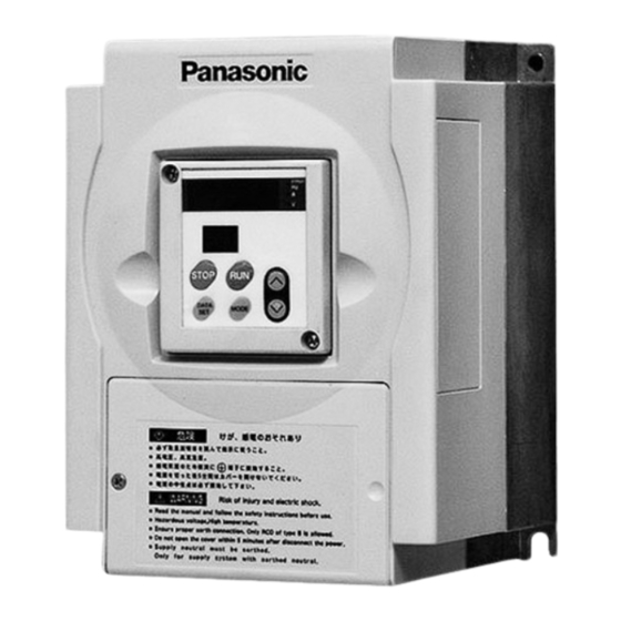
Introduction Unpacking and inspection • Is the model correct? • Was the equipment damaged in transport? If there is anything wrong with the equipment, contact your Panasonic dealer. Checking the inverter model Legend on the nameplate M1SO83CSA M1SO83CSA M1SO83CSA M1SO83CSA... - Page 9 Parts Description Outline and Part Names 0.4 - 7.5kW 0.4 0.4 0.4 7.5kW 7.5kW 7.5kW Example (0.4 to 3.7 kW) Outline Ventilation cover Mounted at four places Case Operation panel mounting screws Operation panel A control dial is equipped on the control dial model. Cover mounting screws Cover Rubber bush for wiring...
-
Page 10: Correct Operation
CAUTION Instructions for safe and correct operation The capacity of the power source must be in the range 1.5 times the inverter capacity to 500 kVA. If the power source has 500 kVA or higher capacity and the length of the cable between it and the inverter is 100 m or less, or if the power source has a phase advancing capacitor selector, excessive peak current will flow into the power source input circuit and may damage the converter. -
Page 11: Installation
Installation Install the inverter properly to prevent equipment failure or accidents. Installation location ① Install the inverter indoors in a place not exposed to rain or direct sunlight. The inverter is not waterproof. ② Install in a place not exposed to corrosive/flammable gases, grinding fluid, oil mist, metal powder or chips. -
Page 12: System Configuration And Wiring
System Configuration and Wiring Wiring general view ● Wiring must be performed by a qualified electrician. ● To avoid electric shock, do not connect the power supply to the unit. No-fuse breaker (NFB) or earth leakage breaker Used to protect the power line. Interrupts the circuit in the case of excessive current. -
Page 13: Inverter And Applicable Peripheral Equipment
Inverter and applicable peripheral equipment Wiring apparatus selection (1) Selection of no-fuse breaker, magnetic contactor, thermal relay, and wiring Magnetic Thermal ∗ Applicable ∗1 No-fuse breaker Wiring (mm contactor relay Inverter No. motor Input (Rated current) (Contact configuration) (Current adjustment range) Output Control (for power... -
Page 14: Wiring
System Configuration and Wiring Wiring Standard wiring diagram ・ ・ ・ ・ 0 0 0 0 .4kW,0 4kW,0.75kW,1 75kW,1.5kW,2 5kW,2.2kW,3 2kW,3.7kW 7kW 4kW,0 4kW,0 75kW,1 75kW,1 5kW,2 5kW,2 2kW,3 2kW,3 7kW 7kW Motor R/L1 U/T1 3-phase power supply S/L2 V/T2 AC380~460V T/L3 W/T3... - Page 15 Wiring ・5 ・5.5kW,7 5kW,7.5kW 5kW ・5 ・5 5kW,7 5kW,7 5kW 5kW Note 2) Regenerative R braking resistor connection terminal P P B Motor R/L1 U/T1 3-phase power supply S/L2 V/T2 AC380~460V T/L3 W/T3 50/60Hz Main circuit Control circuit 5V ③ External frequency setting ②...
-
Page 16: Changing The Input Signal Logic
System Configuration and Wiring Changing the input signal logic The inverter provides two types of input signal logics: sink input and source input. When the “PLC” and “12 V” terminals are short-circuited, sink input is available. When the “PLC” and “G” terminals are short-circuited, source input is available. The inverter has been set for sink input before shipment. -
Page 17: Terminal Function
Terminal function (1) Main circuit terminal 0.4kW - 3.7kW 5.5kW - 7.5kW E R/L1 S/L2 T/L3 U/T1 V/T2 W/T3 E E R/L1 S/L2T/L3 P PB U/T1V/T2 W/T3 E Capacity Terminal Tightening torque Location screw N・m 0.4kW - 7.5kW 1.0 - 1.2 All terminals (including “E”... - Page 18 System Configuration and Wiring (2) Control terminal DSW1* O2 FIN2 FIN1 FOUT I I I I 2 I I I I 4 I I I I 6 < > Relay contact output terminal COM1 12V PLC I I I I 1 I I I I 3 I I I I 5 COM2 NC...
- Page 19 Terminal code Terminal name Function Short-circuiting the “I1” and “G” terminals activates the CCW command. CCW/stop I I I I 1 Opening these terminals activates the stop command. command terminal Short-circuiting the “I2” and “G” terminals activates the CW command. Opening these terminals activates the stop command.
-
Page 20: Precautions When Wiring
System Configuration and Wiring Precautions when wiring Internal circuits retain high voltage for a certain period time after power is off. Wait at least for 15 minutes after power off before starting any wiring. Main circuit (1) If the power supply terminals (R/L1, S/L2 and T/L3) and motor terminals (U/T1, V/T2 and W/T3) are connected in reverse, the inverter will be damaged. -
Page 21: Parameter Setting
Parameter Setting Setting Operation Panel Panasonic Panasonic Panasonic Panasonic r/min A V 5-digit LED 2-digit LED STOP RUN DATA MODE SET * Normally in the monitor mode, the operation panel displays frequency (Hz). * The indicated value is just for reference. Do not use this device as a measuring instrument. - Page 22 Parameter Setting Power ON Monitor mode r/min Output frequency Hz △ MODE ▽ Output current MODE A Direct speed setting of No.0. MODE and ▽ . △ Note: When Speed Converter voltage V setting selection] is MODE DATA SET ● Parameter LED will blink Parameter No.
-
Page 23: Pre-Operation Inspections
Test Operation Pre-operation inspections After installing and wiring, inspect the following before running the inverter. (1) Check if wiring is correct. (In particular, check improper connections of the power supply terminals (R/L1, S/L2 and T/L3) and motor terminals (U/T1, V/T2 and W/T3), short-circuited load and ground fault.) (2) Does input power comply with the rating? (3) Are there any places that could be shorted by wire cuttings, etc? -
Page 24: Selection Of The Run Command
Operation Function Selection of the run command The M2X series inverter provides the following six types of operations depending on whether frequency commands and run commands are entered through the operation panel or the terminal block. Speed command Run command... -
Page 25: Changing Procedure
Acceleration/deceleration time changing procedure Example) Change [ Acceleration time] from Operation panel Step Switch LED display ① Power ON ② Parameter Press DATA SET . number mode ∗1 Using , select the △ parameter No. Press DATA SET . ③ Parameter set value mode Using , select the... -
Page 26: Operation Function
Operation Function Operation function The inverter has the following control functions that are made active from the operation panel and terminal block. Operation control Description Acceleration/deceleration time is set to “0”. This function is optimum for Jogging positioning. By setting [ Operation mode selection] to “2-speed mode”, jogging operation is enabled. - Page 27 <Examples of DC Brake Operation Patterns> Positioning DC brake command Preset deceleration time Time specified by [ DC brake time] Frequency specified by [ Brake start frequency] Output frequency Time determined by GD torque of the load, and [ DC brake intensity] Motor speed vs brake Regenerative...
-
Page 28: Run Mode
Operation Function Run mode The inverter operates in the following two run modes. Select the desired mode in the parameter [ Run mode selection]. Function of terminal block Setting Mode ∗1 ∗1 I I I I 1 I I I I 2 I... - Page 29 ■ Frequency setting selection method for multi-speed operation (1) When [ Multi-speed input selection] is set to (1 BIT): 1-bit input One type of multi-speed frequency can be assigned to one of the [Frequency setting selection] terminals. When the 4-speed, 8-speed and 16-speed operation modes are selected, up to 3-stepped, 4-stepped and 5-stepped speed operations are enabled, respectively.
- Page 30 Operation Function < 16-speed mode > Control terminal number Frequency setting I I I I 3 I I I I 4 I I I I 5 I I I I 6 0th speed frequency OFF OFF OFF OFF 1st speed frequency ON...
- Page 31 ■ Operation pattern in 2-speed mode - Example: When [ I5 function selection] is set to (No. 2 acceleration/deceleration - time) When [ I6 function selection] is set to (External forced trip) Free-run stop Acceleration time (trip) Jogging frequency 0th speed 0th speed Positioning DC brake Acceleration time...
- Page 32 Operation Function ■ Operation pattern in 4-speed mode - Example: When both [ I5 function selection] and [ I6 function selection] are set to - (No. 2 acceleration/deceleration time) No. 4 acceleration time No. 4 deceleration time 1st speed Acceleration time No.
-
Page 33: Protective Function
Protective Function Protective functions Your inverter is equipped with the following protective function that: ① displays warning message, or ② avoids trip without displaying warning message. ③ displays warning message and turns off inverter output, or ④ trips the inverter (the trip signal will be removed upon power off) Display on Type Protective function... - Page 34 Protective Function Display on Type Protective function Corrective action 5-digit LED Restart Prevents the inverter from Issue the stop command once, prevention restarting automatically if already and then issue the run command. when given the run command before ③ power is power is recovered or turned up or restored ∗2...
- Page 35 Display on Type Protective function Corrective action 5-digit LED Radiator fin When the temperature of the Examine the cooling fan and the overheat radiator fin exceeds approx. ambient temperature. protection 100℃, the temperature sensor is activated to trip the inverter. CPU error Trips the inverter if the The microcomputer operation may...
-
Page 36: Canceling Trip
Protective Function Canceling trip First remove the cause and then reset the system by following one of the following steps. [1] Turn off the inverter. Wait until the trip message disappears and then power on again. [2] Leaving the trip message displayed, connect both [I1] and [I2] to [G] for at ∗1 least 0.1 seconds. - Page 37 Maintenance/Inspection You should perform maintenance/inspection on a regular basis in order to ensure safety and keep the inverter in good running order. Precautions when performing maintenance/inspections (1) The power should be turned on/off only by the person performing the task. (2) The internal circuits of the inverter remain charged with high voltage for a short while after power is turned off.
-
Page 38: Of Problem
If you cannot determine the cause of the problem, if you suspect that the inverter is not working properly, if a part is damaged, or there are any other problems you cannot solve, contact your Panasonic dealer. Problem... -
Page 39: Parameter Description
Parameter Description Parameter setting Parameter name ∗1 Check Adjustment range Min. unit Factory setting ∗3 ∗ 2 0.01Hz Set frequency (0th speed) 0, 0.5 - Upper limit frequency ∗3 ∗ 2 0.01Hz 50Hz 1st speed frequency 0, 0.5 - Upper limit frequency ∗3 ∗... - Page 40 Parameter Description Parameter setting Parameter name ∗1 Factory setting Check Adjustment range Min. unit 5 sec Acceleration time - 3 sec : in steps of 0.01 sec 5 sec No.2 acceleration time 0 - 3600 sec : in steps of 0.1 sec 3 sec - 10 sec 5 sec No.3 acceleration time...
- Page 41 Parameter setting Parameter name ∗1 Check Adjustment range Min. unit Factory setting I1/I2 function selection I1: Forward (ccw) /stop I2: Reverse (cw) /stop I1: Run/stop I2: Forward (ccw) /Reverse (cw) I5 function selection Free-run External forced trip 2nd acceleration/deceleration I6 function selection -...
- Page 42 Parameter Description Parameter setting Parameter name ∗1 Check Adjustment range Min. unit Factory setting Monitor mode Set frequency - selection Output frequency - - DC voltage - Output current Feedback frequency - 0.1 - 60.0 Display scale factor - - -...
- Page 43 Parameter setting Parameter name ∗1 Check Adjustment range Min. unit Factory setting Trip cause clear - - - Trip cause① - - - Trip cause② - - - Trip cause③ - - - Trip cause④ - - - Trip cause⑤ Parameter initialization Motor selection 4-pole inverter...
- Page 44 Parameter Description Parameter setting Parameter name ∗1 Check Adjustment range Min. unit Factory setting PID function selection Disables PID control - Enables PID control (Reverse) - Enables PID control (Normal) 0.2 - 5 Proportional (P) gain setting 0.0 - 150.0 sec 0.1 sec 1.0 sec Integral ( I ) time constant setting...
-
Page 45: Detailed Parameter Description
Detailed Parameter Description Function of parameter Parameter name Description Used to specify desired operating frequency. Set frequency Enabled when [ Frequency command selection] is set to (0th speed) 1st speed frequency Used to specify frequency for multi-speed operation. 2nd speed frequency Enabled when [ Operation mode selection] is set to 4-, 8- and 16-speed 3rd speed frequency... - Page 46 Detailed Parameter Description Parameter name Description Selects the run mode. Run mode selection 2-speed mode ● 4-speed mode ■ 8-speed mode ● 16-speed mode ● Torque control : Manual torque boost ■ The inverter’s output voltage in low-frequency range can be Maximum output voltage adjusted Large...
- Page 47 Parameter name Description No.2 acceleration The acceleration time can be set when [ I5 function selection] or [ time I6 function selection] is set to (No. 2 acceleration/deceleration). No.3 acceleration These acceleration times can be set when [ I5 Function selection] and time I6 Function selection] are both set to No.2 acceleration/...
- Page 48 Detailed Parameter Description Parameter name Description Deceleration time Used to determine the output frequency change ratio during deceleration. • Specify the time required for change by 50 Hz. • When this parameter is set to “0” seconds, the actual deceleration time is 0.01 seconds.
- Page 49 Parameter name Description 2nd V/F selection [2nd V/F selection] is used to specify a particular V/F pattern. 2nd V/F base The upper pattern and the lower pattern frequency specified by [2nd V/F base frequency] and [2nd V/F boost], as well as the ordinary V/F pattern can be selected.
- Page 50 Detailed Parameter Description Parameter name Description I5 Function The function of input terminals [I5] and [I6] can be one of the following: selection (FREE) ● : “Terminal”- “G” short-circuited → Free-run stop I6 Function selection ● (THeRmal) : “Terminal”- “G” open→ External forced trip command ●...
- Page 51 Parameter name Description Output signal ① Output signal to terminals [O1], [O2]-[COM1] can be selected as shown below. selection (TRIP) ● Output signal ② trip output signal (trip: on) selection ● (STaBLe) arrival signal (arrive: on) ● (RUN) run/stop signal (run: on) ●...
- Page 52 Detailed Parameter Description Parameter name Description Relay output Used to select the signal type when the relay output terminals (NC, COM2 selection and NO) are used. ■ (TRIP): Trip output signal (During trip: NC - COM2: Open, NO - COM2: Closed) (STaBLe): Arrival signal ●...
- Page 53 Parameter name Description Deceleration Used to adjust the deceleration time when the stall preventing function is factor at stall activated during deceleration. • Define a magnification factor relative to the ordinary deceleration time. Acceleration Linear acceleration/deceleration or S-curve acceleration/deceleration can mode selection be selected.
- Page 54 Detailed Parameter Description Parameter name Description Frequency Used to calibrate the frequency meter. With the △ or ▽ button, adjust parameter the frequency meter’s pointer so that it indicates the full-scale value. adjustment Frequency meter Used to define the frequency meter’s full-scale frequency. The default setting full-scale is 60 Hz.
- Page 55 Parameter name Description Used to adjust the output frequency at power recovery from instantaneous Drop frequency at power failure. instantaneous • At power recovery, the starting frequency is determined by subtracting power failure [Drop frequency at instantaneous power failure] from the output frequency at instantaneous power failure.
- Page 56 Detailed Parameter Description Parameter name Description Used to define the relationship Frequency setting bias Output frequency between the frequency setting Lower limit frequency Upper limit voltage (or current) and the Upper limit frequency frequency output frequency ② frequency command input to ①...
-
Page 57: (Parameter Initialization ・・・・・・・・・・・・・・・・・・・ 59)
Parameter name Description CW rotation Setting this parameter to prevents a trouble caused by CW prevention rotation. range electronic Electronic thermal thermal level. Parameter value • Set the level by the percent of inverter rated current. • When motor current 1 min. - Page 58 Detailed Parameter Description Parameter name Description Starting frequency Used to specify the inverter’s starting output frequency. ∗ Increasing [Starting frequency] enhances the torque start-up. However, this condition is almost direct start, and it is not suitable for shockless start. Furthermore, the inverter may trip depending on the load condition.
- Page 59 Parameter name Description PID function When the PID function is selected, this parameter is used to adjust the selection inverter’s output frequency according to the deviation of the detected value from the target value. Using the PID function enables air flow rate, water flow rate or other parameters to be controlled.
- Page 60 Detailed Parameter Description Parameter name Description Proportional (P) Used to specify proportional gain. gain setting Integral ( I ) time In combination with [ Proportional (P) gain setting], this parameter constant setting defines the output frequency (control quantity) according to the deviation quantity and change with time.
- Page 61 Parameter name Description Equipment No. Indicates a unique number of an inverter in a network. Assign a different equipment number to an individual inverter in a network. When this parameter is set to “80”, access from the host is enabled for broadcast (broadcast for all stations) only. Communication Used to specify the speed of communication between the inverter and speed...
-
Page 62: Copying Parameter
Detailed Parameter Description Copying parameter Parameters can be copied through the operation panel. ∗ To copy parameters, be sure to use the inverters of the same model with the same capacity. [1] Producing master panel Operation panel Step Remarks Switch Display on LED ∗... - Page 63 Operation panel Step Remarks Switch Display on LED <2. Reading parameter values from inverter internal circuit to operation panel> ⑦ Press • Parameter value mode Select [Read DATA SET . parameter out to panel] Using △ , select • 2-digit and 5-digit LEDs will flash. ⑧...
- Page 64 Detailed Parameter Description • 2-digit and 5-digit LEDs flash. ⑫ Write Holding STOP parameter press into DATA SET inverter for 1 second. ⑬ Wait for • is displayed for approx. 10 approx. 3 seconds. seconds • Self-diagnosis trip occurs. ⑭ Parameter values have been written...
-
Page 65: Extracting And Locking Parameters
Extracting and locking parameters Register numbers of parameters that can be edited. After that, these parameters can be edited by calling the number. Example: Only [ Acceleration time] can be set with Operation panel Step Remarks Switch Display on LED •... - Page 66 Detailed Parameter Description Operation panel Step Remarks Switch Display on LED ⑤ Select Press ▽ . Press DATA SET . ⑥ Select Press △ . partial lock Press • Changes stored DATA SET . ⑦ Trip reset • Monitor mode Press △...
-
Page 67: Specifications
Specifications (1) 3-phase power supply specifications M2X044*** M2X084*** M2X154*** M2X224*** M2X374*** M2X554*** M2X754*** Model ∗ 1 0.75 Applicable motor (kW) ∗ 2 10.4 12.8 Output capacity (kVA) Rated output current (A) ∗ 3 3-phase 380 - 460VAC Rated output voltage 3-phase 380... -
Page 68: Dimensions
Dimensions (Unit: mm) Tolerance ± 2 mm ● 0.4 – 3.7kW ● 5.5 – 7.5kW * Use M4 mounting screws. -
Page 69: Conformity To Ec Directive / Ul Standard
Conformity to EC Directive / UL Standard EC Directive The EC Directive is applied to all electronic products that provide proper functions and are exported to EU (European Union) for direct sales for general consumers. These products must conform to the EU uniformed safety standards, and the CE marking that indicates the conformity to the standards must be affixed to the products. -
Page 70: Structure Of Peripheral Equipment
Conformity to EC Directive / UL Standard Structure of peripheral equipment Installation environment Use the inverter in an environment conforming to Pollution Degree 1 or 2 prescribed in IEC60664-1. (Example: Install the inverter in a control panel with IP54 protection structure.) ∗1 Control panel Controller Signal line... -
Page 71: Equipment
Signal line noise filter Connect signal line noise filters to all cables (power cable, motor cable, operation panel remote cable and interface cable). Grounding (1) To prevent an electric shock, be sure to connect the inverter’s protective earth terminal ( ) with the control panel’s protective earth terminal (PE). -
Page 72: Optional Accessories
Optional Accessories Operation panel ■ Operation panel DV0P20704 DV0P20702 Option part number Specification DV0P20704 Standard DV0P20702 With control dial ■ Operation panel cutout dimensions Bore Operation panel remote cable Connector Connector HONDA TSUSHIN KOGYO CO., LTD. HKP-Z11-10MA01#01 HONDA TSUSHIN KOGYO CO., LTD. HKP-Z10-10F02#01 HONDA TSUSHIN KOGYO CO., LTD. - Page 73 Signal line noise filter Option part number Mfg P/N Manufacturer DV0P1460 ZCAT3035-1330 TDK Corporation Frequency meter (DV0P313) Full scale :1 mA φ39 bore 2-φ3.5 bore 40 or less (Mounting pitch)
- Page 74 Recommended Equipment Noise filter( ( ( ( 3SUP-HL○○ ○○ ○○-ER-6B) ) ) ) ○○ ● Manufacturer: Okaya Electric Industries Co., Ltd. Allowable Part No. Applicable motor current 0.4/0.75kW 3SUP-HL5-ER-6B 5.5X7 3SUP-HL10-ER-6B 1.5/2.2kW 5.5X7 3.7/5.5/7.5kW 3SUP-HL30-ER-6B 5.5X7 Surge absorber (R.A.V-801BXZ-4) ● Manufacturer: Okaya Electric Industries Co., Ltd. Circuit diagram ●...
- Page 75 Warranty Period of warranty ● The warranty period for this product shall be one year from the date of purchase. Scope of warranty ● If this product has a defect within the warranty period under the normal operating conditions following this instruction manual, it shall be repaired free of charge. ●...
- Page 76 After-Sale Service (Repair) Repair ● Ask the seller where the product was purchased for details of repair work. When the product is installed in a machine or device, consult first the manufacturer of the machine or device. Memorandum (Fill in the blanks for convenience in case of inquiry or repair) Date of Model No.
Need help?
Do you have a question about the M2X Series and is the answer not in the manual?
Questions and answers