Panasonic S-200PE2E5 Technical Data & Service Manual
Dc inverter
Hide thumbs
Also See for S-200PE2E5:
- Technical data & service manual (252 pages) ,
- Operating instructions manual (7 pages) ,
- Technical data & service manual (38 pages)

Subscribe to Our Youtube Channel
Related Manuals for Panasonic S-200PE2E5


Summary of Contents for Panasonic S-200PE2E5
- Page 1 SM830194-11CE TECHNICAL DATA & SERVICE MANUAL Indoor Unit Outdoor Unit Type E2 S-200PE2E5, S-250PE2E5 Type E1 S-200PE1E8A, S-200PE1E8, S-250PE1E8 U-200PE1E8, U-250PE1E8 SM830194-04 REFERENCE NO 85464849294004...
- Page 2 IMPORTANT! • Provide a power outlet to be used exclusively for each unit. Please Read Before Starting • Provide a power outlet exclusively for This air conditioner must be installed by the sales dealer each unit, and full disconnection means or installer.
- Page 3 …In a Snowy Area (for Heat Pump- • Keep your fingers and clothing away type Systems) from any moving parts. Install the outdoor unit on a raised • Clean up the site after you finish, platform that is higher than drifting snow. remembering to check that no metal Provide snow vents.
-
Page 4: Check Of Density Limit
Check of Density Limit The standards for minimum room volume are as follows. (1) No partition (shaded portion) The room in which the air conditioner is to be installed requires a design that in the event of refrigerant gas leaking out, its density will not exceed a set limit. The refrigerant (R410A), which is used in the air conditioner, is safe, without the toxicity or combustibility of ammonia, and is not restricted by laws imposed to protect the ozone layer. -
Page 5: Table Of Contents
—— CONTENTS —— Section 1. SPECIFICATIONS ....................1-1. Unit Specifications ....................... 1-2. Major Component Specifications ..................1-3. Other Component Specifications ..................1-14 1-4. Dimensional Data ....................... 1-16 1-5. Refrigerant Flow Diagram ....................1-21 1-6. Operating Range ........................ 1-24 1-7. Capacity Correction Graph According to Temperature Condition ........ 1-25 1-8. - Page 6 5-1. Meaning of Alarm Messages ....................5-2. Contents of LED Display on the Outdoor Unit Control PCB..........5-3. Symptoms and Parts to Inspect ..................5-4. Details of Alarm Messages ....................5-5. Table of Thermistor Characteristics ................. 5-14 5-6. How to Remove the Compressor ..................5-15 5-7.
- Page 7 1. SPECIFICATIONS 1-1. Unit Specifications..................... 1-2. Major Component Specifications ................1-3. Other Component Specifications ................1-14 1-4. Dimensional Data ..................... 1-16 1-5. Refrigerant Flow Diagram ..................1-21 1-6. Operating Range ...................... 1-24 1-7. Capacity Correction Graph According to Temperature Condition ..... 1-25 1-8.
-
Page 8: Unit Specifications
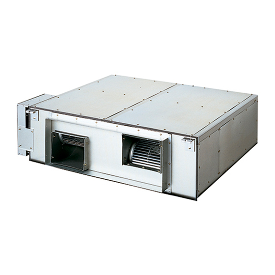
Single-Type 1-1. Unit Specifications High Static Pressure Ducted Type S-200PE2E5 / U-200PE1E8 INDOOR MODEL S-200PE2E5 PANEL MODEL OUTDOOR MODEL U-200PE1E8 Branch pipe MODEL PERFORMANCE TEST CONDITION ISO13253 / EN14511 / EN12102 ø, Hz 1ø 50Hz 3ø 50Hz POWER SUPPLY 19.5 19.5... - Page 9 Single-Type High Static Pressure Ducted Type S-250PE2E5 / U-250PE1E8 INDOOR MODEL S-250PE2E5 PANEL MODEL OUTDOOR MODEL U-250PE1E8 Branch pipe MODEL PERFORMANCE TEST CONDITION ISO13253 / EN14511 / EN12102 ø, Hz 1ø 50Hz 3ø 50Hz POWER SUPPLY 25.0 25.0 25.0 22.4 CAPACITY BTU/h 85300...
- Page 10 Single-Type High Static Pressure Ducted Type S-200PE1E8A / U-200PE1E8 Indoor Unit S-200PE1E8A MODEL No. Outdoor Unit U-200PE1E8 Indoor Unit 220-230-240V, 50Hz, single-phase POWER SOURCE Outdoor Unit 380-400-415V, 50/60Hz, 3-phase PERFORMANCE Cooling Heating 20.0 [6.0~22.4] 21.8 [6.0~22.4] Capacity [min~max] BTU / h 68,200 [20,500~76,400] 74,400 [20,500~76,400] Air circulation (Hi / Me / Lo)
- Page 11 Single-Type High Static Pressure Ducted Type S-200PE1E8 / U-200PE1E8 Indoor Unit S-200PE1E8 MODEL No. Outdoor Unit U-200PE1E8 Indoor Unit 220-230-240V, 50/60Hz, single-phase POWER SOURCE Outdoor Unit 380-400-415V, 50/60Hz, 3-phase PERFORMANCE Cooling Heating 20.0 [6.0~22.4] 22.4 [6.0~25.0] Capacity [min~max] BTU / h 68,200 [20,500~76,400] 76,400 [20,500~85,300] Air circulation (Hi / Me / Lo)
- Page 12 Single-Type High Static Pressure Ducted Type S-250PE1E8 / U-250PE1E8 Indoor Unit S-250PE1E8 MODEL No. Outdoor Unit U-250PE1E8 Indoor Unit 220-230-240V, 50/60Hz, single-phase POWER SOURCE Outdoor Unit 380-400-415V, 50/60Hz, 3-phase PERFORMANCE Cooling Heating 25.0 [6.0~28.0] 28.0 [6.0~31.5] Capacity [min~max] BTU / h 85,300 [20,500~95,500] 95,500 [20,500~107,500] Air circulation (Hi / Me / Lo)
-
Page 13: Major Component Specifications
1-2. Major Component Specifications (A) Indoor Units High Static Pressure Ducted Type S-200PE2E5 MODEL No. S-200PE2E5 Source 220 - 230 - 240V, single-phase, 50Hz Controller P.C.B. Ass'y CR-280ME2E5 Fan (Number...diameter) SIROCCO (2...ø250) Fan motor DMUB6D1AC...560W Model...Nominal output DMUB6D2AC...560W Power source 100 - 391 VDC No. - Page 14 (A) Indoor Units High Static Pressure Ducted Type S-250PE2E5 MODEL No. S-250PE2E5 Source 220 - 230 - 240V, single-phase, 50Hz Controller P.C.B. Ass'y CR-280ME2E5 Fan (Number...diameter) SIROCCO (2...ø250) Fan motor DMUB8D1AC...560W Model...Nominal output DMUB8D2AC...560W Power source 100 - 391 VDC No.
- Page 15 (A) Indoor Units High Static Pressure Ducted Type S-200PE1E8A MODEL No. S-200PE1E8A Source 220 - 230 - 240V, single-phase, 50Hz Controller P.C.B. Ass'y CR-UXRP71B-P (Microprocessor) Fan (Number...diameter) Centrifugal (2...ø250) Fan motor Model...Nominal output KFC4X-401B3P...400W Power source 220 - 230 - 240V, single-phase, 50Hz No.
- Page 16 (A) Indoor Units High Static Pressure Ducted Type S-200PE1E8 MODEL No. S-200PE1E8 Source 220 - 230 - 240V, single-phase, 50/60Hz Controller P.C.B. Ass'y CR-UXRP71B-P (Microprocessor) Fan (Number...diameter) Centrifugal (2...ø220) Fan motor Model...Nominal output KFC4X-201B5P...180W Power source 220 - 230 - 240V, single-phase, 50Hz No.
- Page 17 (A) Indoor Units High Static Pressure Ducted Type S-250PE1E8 MODEL No. S-250PE1E8 Source 220 - 230 - 240V, single-phase, 50Hz Controller P.C.B. Ass'y CR-UXRP71B-P (Microprocessor) Fan (Number...diameter) Centrifugal (2...ø250) Fan motor Model...Nominal output KFC4X-401B3P...400W Power source 220 - 230 - 240V, single-phase, 50Hz No.
- Page 18 (B) Outdoor Units U-200PE1E8 MODEL No. U-200PE1E8 Source 380-400-415V, 3-phase, 50/60Hz Controller P.C.B. Ass'y CR-C906VH8P (Microprocessor) Control circuit fuse Compressor Model..number C-9RVN273H0K Source 246V (DC) / 3-phase / 60Hz (Inverter drive) Nominal output 4,200 Compressor oil 1,400 C – R : 0.552 R –...
- Page 19 (B) Outdoor Units U-250PE1E8 MODEL No. U-250PE1E8 Source 380-400-415V, 3-phase, 50/60Hz Controller P.C.B. Ass'y CR-C906VH8P (Microprocessor) Control circuit fuse Compressor Model..number C-9RVN393H0U Source 282V (DC) / 3-phase / 60Hz (Inverter drive) Nominal output 5,500 Compressor oil 1,900 C – R : 0.608 R –...
-
Page 20: Other Component Specifications
1-3. Other Component Specifications Outdoor Units U-200PE1E8 MODEL No. Outdoor Unit U-200PE1E8 Power Transformer – Rated – Source VAC, Hz – – Secondary – Coil resistance Ω – Thermal cut off temperature Thermistor (Coil / Air sensor): TH1, TH2, TH3, TH4 KTM-35D-S1, DTN-C532G3H Resistance kΩ... - Page 21 Outdoor Units U-250PE1E8 MODEL No. Outdoor Unit U-250PE1E8 Power Transformer – Rated – Source VAC, Hz – – Secondary – Coil resistance Ω – Thermal cut off temperature – Thermistor (Coil / Air sensor): TH1, TH2, TH3, TH4 KTM-35D-S1, DTN-C532G3H Resistance kΩ...
-
Page 22: Dimensional Data
1-4. Dimensional Data (A) Indoor Units: High Static Pressure Ducted Type S-200PE2E5 S-250PE2E5 Unit : mm Refrigerant liquid tubing (Flare) Type 200: ø9.52 Port for optional wiring part Type 250: ø12.7 Drain port 25A Refrigerant gas tubing (Brazing) ø25.4 mm... - Page 23 (A) Indoor Units: High Static Pressure Ducted Type S-200PE1E8A unit: mm Refrigerant liquid line 200: ø9.52, 250: ø12.7 Refrigerant gas line ø25.4 Power supply outlet Drain port (OD 32 mm) Duct connection for suction Duct connection for discharge × 12 4 - 37 1170 (Suspension bolt pitch) (Hole for suspension bolt)
- Page 24 (A) Indoor Units: High Static Pressure Ducted Type S-200PE1E8 S-250PE1E8 1170 (Suspension bolt pitch) 4 - 37×12 (Hole for suspension bolt) 1100 1222 1-18...
- Page 25 (B) Outdoor Unit: U-200PE1E8 Unit: mm Mounting hole (4-R6.5), anchor bolt : M10 Refrigerant tubing (liquid tube), flared connection (ø9.52) Refrigerant tubing (gas tube), flared connection (ø19.05) Refrigerant tubing port Electrical wiring port (ø16) 2 x ø32 holes (holes for drain) Electrical wiring port (ø19) Of the 4 ø32 holes , use 1 of the 2 holes Electrical wiring port (ø29)
- Page 26 (B) Outdoor Unit: U-250PE1E8 Unit: mm Mounting hole (4-R6.5), anchor bolt : M10 Refrigerant tubing (liquid tube), flared connection (ø12.7) Refrigerant tubing (gas tube), flared connection (ø19.05) Refrigerant tubing port Electrical wiring port (ø16) 2 x ø32 holes (holes for drain) Electrical wiring port (ø19) Of the 4 ø32 holes , use 1 of the 2 holes Electrical wiring port (ø29)
-
Page 27: Refrigerant Flow Diagram
1-5. Refrigerant Flow Diagram Cooling cycle Heating cycle Outdoor Unit : U-200PE1E8 Indoor Unit : S-200PE2E5 Accumulator Accumulator Compressor Strainer Solenoid Gas line valve service valve (3/4") High pressure ø25.4 (brazing) switch Heat exchanger Check valve 4-way valve Heat Distributor... - Page 28 Cooling cycle Heating cycle Outdoor Unit : U-200PE1E8 Indoor Unit : S-200PE1E8A Accumulator Accumulator Compressor Strainer Solenoid Gas line valve service valve (3/4") High pressure ø25.4 (brazing) switch Heat exchanger Check valve 4-way valve Heat Distributor exchanger Freeze-prevention coil (Attached to the heat exchanger) Strainer Solenoid Liquid line...
- Page 29 Cooling cycle Heating cycle Outdoor Unit : U-200PE1E8 Indoor Unit : S-200PE1E8 Accumulator Accumulator Compressor Strainer Solenoid Gas line valve service valve (3/4") High pressure ø25.4 (brazing) switch Heat exchanger Check valve 4-way valve Heat Distributor exchanger Freeze-prevention coil (Attached to the heat exchanger) Strainer Solenoid Liquid line...
-
Page 30: Operating Range
1-6. Operating Range S-200PE2E5 − U-200PE1E8 S-250PE2E5 − U-250PE1E8 S-200PE1E8A − U-200PE1E8 Temperature Indoor air intake temp. Outdoor air intake temp. Maximum 32°C DB 43°C DB Cooling Minimum 18°C DB –15°C DB Maximum 30°C DB 15°C DB Heating Minimum 16°C DB –20°C DB... -
Page 31: Capacity Correction Graph According To Temperature Condition
1-7. Capacity Correction Graph According to Temperature Condition U-200PE1E8 / U-250PE1E8 (For 50 Hz and 60 Hz) Cooling capacity ratio (maximum capacity) Heating capacity ratio (maximum capacity) Indoor air intake temp (WB) °C Indoor air intake temp ( °C °C °C 22WB 19WB... -
Page 32: Noise Criterion Curves
1-8. Noise Criterion Curves High Static Pressure Ducted Type HIGH MODEL : S-200PE2E5 : S-250PE2E5 MODEL SOUND LEVEL : HIGH 43 dB(A) SOUND LEVEL : HIGH 47 dB(A) 38 dB(A) 42 dB(A) CONDITION : Under the unit 1.5 m CONDITION : Under the unit 1.5 m... - Page 33 Standard (B) Outdoor Unit Quiet mode COOLING : U-200PE1E8 MODEL MODEL : U-200PE1E8 : 72 dB(A) SOUND LEVEL : STANDARD 57 dB(A) SOUND POWER LEVEL : Cooling QUIET MODE 50 dB(A) CONDITION : 1 m in front at height of 1.5 m NC-70 NC-70 NC-60...
- Page 34 Standard (B) Outdoor Unit Quiet mode COOLING : U-250PE1E8 MODEL : U-250PE1E8 MODEL : 72 dB(A) SOUND SOUND LEVEL : STANDARD 57 dB(A) POWER LEVEL : Cooling QUIET MODE 50 dB(A) CONDITION : 1 m in front at height of 1.5 m NC-70 NC-70 NC-60...
-
Page 35: Electrical Wiring
15 A U-250PE1E8 14 mm 96 m 20 A Indoor unit (B) Power supply Time delay fuse or circuit capacity 2.5 mm S-200PE2E5 Max. 30 m 10-16 A S-250PE2E5 S-200PE1E8A Max. 50/30 m 10/16 A S-200PE1E8 Max. 50/30 m 10/16 A... - Page 36 Wiring System Diagrams <Type E2> Indoor unit Power supply Outdoor unit 220/230/240V ~ 50 Hz INV unit Power supply Ground Remote 380/400/415V, 3 N~, 50/60 Hz controller Ground Ground Outdoor Unit NOTE 5P terminal board (1) Refer to “Recommended Wire Length and Wire Diameter for Power Supply System”...
- Page 37 CAUTION (1) When linking the outdoor units in a network, disconnect the terminal extended from the short plug from all outdoor units except any one of the outdoor units. (When shipping: In shorted condition.) For a system without link (no wiring connection between outdoor units), do not remove the short plug. (2) Do not install the inter-unit control wiring in a way that forms a loop.
- Page 38 <Type E1> Indoor unit Power supply* Outdoor unit (3-phase) 220 – 240 V ~50/60 Hz INV unit Power supply Ground Remote 380 – 415 V, 3N, ~ 50/60 Hz controller Ground Ground * Regarding S-250PE1E8, the power supply is 220-240V, 50Hz only. NOTE 7P terminal board (1) Refer to “Recommended Wire Length and Wire...
- Page 39 Stranded wire How to connect wiring to the terminal For stranded wiring Ring pressure terminal Cut the wire end with cutting pliers, then strip the insulation to expose the stranded wiring about 10 mm and tightly twist the wire ends. (Fig. 1-7) Fig.
-
Page 40: Installation Instructions
1-10. Installation Instructions Outdoor Unit Tubing Length (A) Single type During tubing work, try to make both the tubing length (L) Single and the difference in elevation (H1) as short as possible. Refer to Table 1-1. Main tubing L Table 1-1 Tubing Data for Models (Single) Models U-200PE1E8 U-250PE1E8... - Page 41 (B) Simultaneous operation multi (Twin, Triple, Double-Twin) (B) Simultaneous operation multi (Twin, Triple, Double-Twin) NOTE Because the indoor units run simultaneously, install them within the same room. Table 1-2 Table for Managing Tubing Length and Height Differential Actual Symbol Item Contents length Single...
- Page 42 Table 1-3 Connection Tube Sizes (Twin, Triple, Double-Twin) Double-Twin distribution tube (L1, L2) Indoor unit connection tube Main tubing (L) ( 1, 2, 3, 4) Total type capacity of indoor unit connected after the branch Type capacity of indoor unit 100 - 125 60 - 125 Gas tube...
-
Page 43: Check Of Limit Density
This unit requires no additional refrigerant CAUTION charge up to tubing length 30 m. In case of more than 30 m, additional refrigerant charge is required. Refer to Tables 1-1 and 1-3. In case of multi type installation, indoor units should be installed within the same room. -
Page 44: Optional Distribution Joint Kits
Optional Distribution Joint Kits CZ-P155BK1: Cooling capacity after distribution is 16.0 kW (54,600 BTU/h) or less. CZ-P680BK2: Cooling capacity after distribution is more than 16.0 kW (54,600 BTU/h) and less than 68.0 kW (232,000 BTU/h). CZ-P3HPC2: Cooling capacity after distribution is 28.0 kW (95,500 BTU/h) or less. Table 1-5 Distribution Branch Size ( 1, 2, 3, 4, ) Unit: mm (in.) Indoor Unit... - Page 45 I nstalling Distribution Joint Kit (for Twin & Double-Twin) (CZ-P155BK1 & CZ-P680BK2) Horizontal installation For branching tubes, install 150 mm or longer (including reducer) straight tubing up to the point where the tube Horizontal line branches (or after the point where the tubes join together). indoor unit side Outdoor unit side 150 mm or longer straight tubing up...
- Page 46 Installing Distribution Joint Kit (for Triple) (CZ-P3HPC2) Check the system combination before installing the distribution joints. Three indoor units must be installed within the same room. Use the supplied tube connectors to adjust the tube sizes of the distribution joints. How to Install Distribution Joints Use the supplied distribution joints to complete refrigerant tubing Distribution joint insulation material (supplied)
-
Page 47: Selecting The Installation Site
3. SELECTING THE INSTALLATION SITE CAUTION When moving the unit during or after unpacking, make sure to lift it by holding its lifting lugs. Do not exert any pressure on other parts, especially the refrigerant piping, drain piping and flange parts. If you think the humidity inside the ceiling might exceed 30°C and RH 80%, reinforce the insulation on the unit body. - Page 48 Installation space Install the outdoor unit with a sufficient space around the outdoor unit for operation and maintenance. (1) Obstructions on the left side, right side and rear side (Front side and above the unit are opened). (Fig. 1-14) * Necessary space is required to unscrew on the rear side for maintenance and if a sufficient maintenance space is provided on the rear side (40 cm), the space of over 15 cm is enough at the right side.
- Page 49 Air Discharge Chamber for Top Discharge Air discharge Be sure to install the air discharge chamber in the field when: It is difficult to keep a space of min. 1 m between the air discharge outlet and an obstacle. The air discharge outlet is facing to the sidewalk and discharged hot air annoys the passers-by.
-
Page 50: Dimensions Of Air-Discharge Chamber
4. Dimensions of Air-Discharge Chamber : In snowy regions, if there is concern that snow may enter the air discharge chamber, remove the base of the chamber before using. Unit: mm Reference diagram for U-200PE1E8 / U-250PE1E8 Air discharge support Air intake Downward, Left side installation fixture T1.0... - Page 51 Reference diagram for downward left side installation fixture (field supply) : Unit: mm 2-ø3.3 protrusion hole (reverse side) Reference diagram for downward right side installation fixture (field supply) : Unit: mm 2-ø3.3 protrusion hole (reverse side) Cyclic bending 1-45...
- Page 52 Reference diagram for downward center side installation fixture (field supply) : Unit: mm Cyclic bending 32.5 (495) 32.5 Same on reverse side (135) 1-46...
- Page 53 Reference diagram for upward left side installation fixture (field supply) : Unit: mm 10.5 145.5 Reference diagram for upward right side installation fixture (field supply) : Unit: mm 10.5 135.5 1-47...
- Page 54 Reference diagram for upward left side installation fixture (field supply) : Unit: mm 2-ø3.3 protrusion hole (reverse side) 561.5 Reference diagram for upward right side installation fixture (field supply) : Unit: mm 2-ø3.3 protrusion hole (reverse side) Cyclic bending 1-48...
- Page 55 Reference diagram for air-discharge chamber (field supply) The models of U-200PE1E8 / U-250PE1E8 with Air-Discharge Chamber Required space around outdoor unit If the air discharge chamber is used, the space shown below must be secured around the outdoor unit. If the unit is used without the required space, a protective device may activate, preventing the unit from operating. (1) Single-unit installation Unit: mm The top and both sides must remain open.
-
Page 56: Dimensions Of Wind-Proof Duct
5. Dimensions of Wind-proof Duct : In snowy regions, if there is concern that snow may enter the wind-proof duct, remove the base of the chamber before using. Reference diagram for U-200PE1E8 / U-250PE1E8 Air intake Unit: mm discharge discharge Air discharge discharge discharge... -
Page 57: Dimensions Of Snow-Proof Duct
6. Dimensions of Snow-proof Duct : Reference diagram for U-200PE1E8 / U-250PE1E8 (295) Unit: mm Air Intake Air discharge (227) (303) Air discharge Air discharge Air Intake Reference diagram for snow-proof duct (field supply) : Unit: mm Unit top, snow-proof duct Unit right side Unit left side Unit front side... - Page 58 Reference diagram for snow-proof duct - 1 Space requirements for setting - (1) The models of U-200PE1E8 / U-250PE1E8 with snow-proof duct Unit: mm [Obstacle to the rear of unit] [Obstacle to the front of unit] z Top is open: z Top is open: Single-unit installation (2) Obstacles on both sides Single-unit installation...
- Page 59 Reference diagram for snow-proof duct - 2 Space requirements for setting - (2) The models of U-200PE1E8 / U-250PE1E8 with snow-proof duct [Obstacles to the front and rear of unit] z The top and both sides must remain open. Either the obstacle to the front or the obstacle to the rear must be no taller than the height of the outdoor unit.
-
Page 60: How To Install The Outdoor Unit
7. HOW TO INSTALL THE OUTDOOR UNIT 1. Installing the Outdoor Unit For 8 and 10 HP unit Unit: mm Use concrete or a similar material to make the base, and ensure good drainage. 2- o32 Specified drain port Ordinarily, ensure a base height of 5 cm or more. Air Intake If a drain pipe is used, or for use in cold-weather regions, ensure a height of 15 cm or more at the feet... -
Page 61: Indoor Unit
Indoor Unit 8. SELECTING THE INSTALLATION SITE CAUTION When moving the unit during or after unpacking, make sure to lift it by holding its lifting lugs. Do not exert any pressure on other parts, especially the refrigerant piping, drain piping and flange parts. If you think the humidity inside the ceiling might exceed 30°C and RH 80%, reinforce the insulation on the unit body. -
Page 62: How To Install The Indoor Unit
9. HOW TO INSTALL THE INDOOR UNIT <Type E2> 9-1. Required Minimum Space for Installation and Service (1) Dimensions of suspension bolt pitch and unit Unit: mm 1170 (Suspension bolt pitch) (60) (60) 1100 Inspection access (600 × 600)(Field supply) Min. - Page 63 9-2. Suspending the Indoor Unit Depending on the ceiling type: 1. Check the suspension bolt pitch. 2. Ensure that the ceiling is strong enough to support the weight of the unit. 3. To prevent the unit from dropping, firmly fasten the suspension bolts as shown in the figure below. Unit: mm Hole-in-anchor Hexagonal nut (field supply)
-
Page 64: Gas Tube Ø
9-3. Installing the Refrigerant Tubing The size of the refrigerant tubing is as shown in the table below. Table 1-6 Type ø25.4 ø25.4 Gas tube (Brazing connection) (Brazing connection) ø9.52 (Flare connection) ø12.7 (Flare connection) Tightening torque (approximate) : 34 ~ 42 N · m Tightening torque (approximate) : 34 ~ 42 N·m Liquid tube Thickness of connecting tube : 0.8 mm... - Page 65 9-4. Installing the Drain Piping Sealing tape Prepare standard hard PVC pipe (O.D. 32 mm) for the drain and use the supplied drain socket to prevent water leaks. The PVC pipe must be purchased separately. When doing this, apply adhesive for the PVC pipe at the Drain socket connection point.
- Page 66 9-5. Caution for Ducting Work • This unit has high static pressure. In case of small pressure resistance (for instance, a short duct), install an airflow control damper (field supply) for adjusting airflow volume as airflow volume / airflow noise increases. •...
- Page 67 9-6. External Static Pressure Setting Choose one of the methods (selection of “a”, “b”, “c” within the range of dotted line as shown in the flowchart below) and make settings. a. No setting changes: When using as it is factory preset at shipment. (If resetting after external static pressure setting once, it might be different from factory preset.) b.
- Page 68 9-6-1. How to Set on PC Board 1. Turn off the power breaker to halt the supply of electricity to the PC board. 2. Open the lid of the electrical component box and confirm the location where the Select switch on the indoor unit control PCB is placed.
- Page 69 9-6-3. Operating the High-spec Wired Remote 3. Select the “Code no.” by pressing the Controller (CZ-RTC3) button. Change the “Code no.” to “5D” by pressing the button (or keeping it pressed). 20:30 (THU) Detailed settings 20:30 (THU) Unit no. Code no. Set data START Sel.
- Page 70 Indoor Fan Performance Cooling Heating Cooling Item code “ ” Heating Cooling Setting at shipment Heating Type 200 Type 250 (Pa) (Pa) Airflow Volume (m /min.) Airflow Volume (m /min.) Fig. 1-32 1-64...
- Page 71 <Type E1> Unit: mm 9-7. Required Minimum Space for Installation and Service The installation instructions that come with the indoor unit 1170 Min. 600 (Suspension bolt pitch) describe how to use it in combination with the U-200PE1E8 (Space for 1100 service) and U-250PE1E8 outdoor units.
- Page 72 9-8. Suspending the Indoor Unit Depending on the ceiling type: Insert suspension bolts as shown in Fig. 1-35 Use existing ceiling supports or construct a suitable support as shown in Fig. 1-36. Hole-in-anchor Concrete Insert Hole-in-plug Ceiling tiles Ceiling support Suspension bolt (M10 or 3/8”) (field supply) Fig.
- Page 73 The Type 200 indoor unit comes with a tube connector Remove the ø 12.7 flare nut from the liquid tubing of that is for liquid tubing. Configure as shown in the the indoor unit and use it. illustration and connect it. When flaring the tube, put the flare nut onto it first To Indoor unit and then flare it.
-
Page 74: How To Process Tubing
1-11. HOW TO PROCESS TUBING <Type E2> The liquid tubing side is connected by a flare nut, and the gas tubing side is connected by brazing. 1. Connecting the Refrigerant Tubing Use of the Flaring Method Many of conventional split system air conditioners employ the flaring method to connect refrigerant tubes that run between indoor and outdoor units. -
Page 75: Ø6.35
Caution Before Connecting Tubes Tightly (1) Apply a sealing cap or water-proof tape to prevent dust or water from entering the tubes before they are used. Apply refrigerant lubricant. (2) Be sure to apply refrigerant lubricant (ether oil) to the inside of the flare nut before making piping connections. - Page 76 3. Insulating the Refrigerant Tubing Two tubes arranged together Tubing Insulation Gas tubing Liquid tubing Thermal insulation must be applied to all units tubing, including distribution joint (field supply). * For gas tubing, the insulation material must be heat resistant to 120°C or above. For other tubing, it must be resistant to 120°C or above.
- Page 77 <Type E1> The liquid tubing side is connected by a flare nut, and the gas tubing side is connected by brazing. 1. Connecting the Refrigerant Tubing Use of the Flaring Method Many of conventional split system air conditioners employ the flaring method to connect refrigerant tubes that run between indoor and outdoor units.
- Page 78 Caution Before Connecting Tubes Tightly Apply a sealing cap or water-proof tape to prevent dust or water from entering the tubes before they are used. Be sure to apply refrigerant lubricant (ether oil) to the Apply refrigerant lubricant. inside of the flare nut before making piping connections. This is effective for reducing gas leaks.
-
Page 79: Ø6.35
3. Out Rear 4. Out Bottom Flare Process Flare Process The ø25.4 gas main will not pass easily into the opening for coolant pipes in the pipe cover, so make sure you connect the ø25.4 pipe with the ø19.05 pipe outside of the outdoor unit. (2) Tightly connect the indoor-side refrigerant tubing Torque wrench extended from the wall with the outdoor-side tubing. - Page 80 In order to prevent damage to the flare caused by over-tightening of the flare nuts, use the table above as a guide when tightening. When tightening the flare nut on the liquid tube, use an adjustable wrench with a nominal handle length of 200 mm.
- Page 81 4. Taping the Tubes (1) At this time, the refrigerant tubes (and electrical wiring if local codes permit) should be taped together with armoring tape in 1 bundle. To prevent condensation Inter-unit Gas tube Liquid tube control wiring from overflowing the drain pan, keep the drain hose separate from the refrigerant tubing.
-
Page 82: Leak Test, Evacuation And Additional Refrigerant Charge
1-12. LEAK TEST, EVACUATION AND ADDITIONAL REFRIGERANT CHARGE Perform an air-tightness test for this package A/C. Check that there is no leakage from any of the connections. Air and moisture in the refrigerant system may have undesirable effects as indicated below. pressure in the system rises operating current rises cooling (or heating) efficiency drops... - Page 83 2. Evacuation Be sure to use a vacuum pump that includes a function for prevention of back-flow, in order to prevent back-flow of pump oil into the unit tubing when the pump is stopped. Manifold valve Perform vacuuming of the indoor unit and tubing. Connect the vacuum pump to the gas tube valve and apply vacuum at a pressure of –101kPa {–755 mmHg, 5 Torr} or below.
-
Page 84: How To Select Ahu System
1-13. How to select AHU system AHU system selection guideline System lineup Capacity Outdoor combination Connectable AHU-kit combination 20 kW U-200PE1E8 CZ-280PAH1 25 kW U-250PE1E8 CZ-280PAH1 * Single connection type only * Mix connection with standard indoor units is not allowed. * The system is applicable to the above models. - Page 85 Installation Installation of Strainer (Field supplied) Attach the strainer to the side of the outdoor unit for Gas & Liquid piping. (See the “System Overview” on previous page.) Thermistor for Liquid pipe and Heat exchanger pipe middle Liquid pipe thermistor Attach the liquid pipe thermistor Cover the thermistor Cover the aluminum...
- Page 86 Blower operation signal and protection signal Blower signal output Power supply Minimum applicable load DC 5 V, 1 mA Maximum applicable load AC 230 V, 2 A X1 : Relay (field supply) Blower protect input SW 1 : operation command (field supply) AC 220 ~240 V, 0.1 A Limitation of AHU When the AHU is selected, there are some limitations.
- Page 87 Restriction on the number of passes of the heat exchanger hairpin Minimum number of passes = Number of steps × Distance between tube sheets × Number of rows × 1.5 ×10 <For example> Number of steps Distance between tube sheets 1000 [mm] Number of rows Minimum number of passes = 12 ×...
- Page 88 – MEMO – 1-82...
-
Page 89: Table
2. TEST RUN 2. TEST RUN 2-1. Preparing for Test Run ..................... 2-2 Indoor Units (Type E2, E1) 2-2. Caution ........................2-3. Test Run Procedure ....................2-4. Items to Check Before the Test Run ............... 2-5. Test Run Using the Remote Controller .............. -
Page 90: Test Run
2-1. Preparing for Test Run Before attempting to start the air conditioner, check the following: (1) All loose matter is removed from the cabinet especially steel filings, bits of wire, and clips. (2) The control wiring is correctly connected and all (Power must be turned ON at least electrical connections are tight. -
Page 91: Items To Check Before The Test Run
2-4. Items to Check Before the Test Run (1) Turn the remote power switch ON at least 12 hours in advance in order to energize the crankcase heater. Fully open the closed valves on the liquid-tube and gas-tube sides. 2-5. Test Run Using the Remote Controller (1) Press and hold the remote controller button for 4 seconds or longer. -
Page 93: Outdoor Unit Amount Of
2-8. System Control System control refers to the link wiring connection for control of simultaneous-operation multi systems, group control, and main-sub remote controller control. 2-8-1. Basic wiring diagram Single type Be careful to avoid miswiring when connecting the wires. (Miswiring will damage the units.) (for 3-phase Outdoor unit) System address rotary switch Ground... - Page 94 2-8-2. Setting the Outdoor unit system addresses For basic wiring diagram (Set the system address: 1) Outdoor unit control PCB 8 – 10 HP OC (CN500, BLU) EMG (CN502, BRN) 63PH (CN027, WHT) System address rotary switch SILENT (CN037, WHT) FUSE (0.5A, F500) (Set to “0”...
- Page 95 2-8-4. Indicating (marking) the Indoor and Outdoor unit combination number Indicate (mark) the number after automatic address setting is completed. (1) So that the combination of each indoor unit can be easily checked when multiple units are installed, ensure that the indoor and outdoor unit numbers correspond to the system address number on the outdoor unit control PCB, and use a magic marker or similar means which cannot be easily erased to indicate the numbers in an easily visible location on the indoor units (near the indoor unit nameplates).
-
Page 96: Test Run Procedure
2-9. Test Run Procedure Recheck the items to check before the test run. (See 2-10) Check the combination (wiring) of indoor and outdoor units. (See 2-15) Is system “single-type”? (1 indoor unit is connected to 1 outdoor unit) Are multiple outdoor units used? (See 2-15-2) Turn ON the indoor and... -
Page 97: Items To Check Before The Test Run
2-10. Items to Check Before the Test Run Turn the remote power switch ON at least 12 hours in advance in order to energize the crankcase heater. Fully open the closed valves on the liquid-tube and gas-tube sides. 2-11. Preparation for Test Run 2-11-1. -
Page 98: Test Run
2-12. Test Run Using the control unit (1) Change the indoor control unit switch from “ON” “TEST”. Indoor control unit switch (The outdoor unit will not operate for 3 minutes after the power is turned ON and after operation is stopped.) (2) All the indicator lamps blink while the test run is in progress. -
Page 99: Table Of Self-Diagnostic Functions And Corrections
2-14. Table of Self-Diagnostic Functions and Corrections Cause Wired remote controller Indoor unit Group connection Correction display receiver lamp 1:1 connection (Single type) (Simultaneous multi (Field supply) system) Nothing is Nothing is • Indoor operation switch is OFF. • Same at left. •... -
Page 100: L1 L2
2-15. System Control System control refers to the link wiring connection for control of simultaneous-operation multi systems, group control, and main-sub remote controller control. 2-15-1. Basic wiring diagram 1 Single type Be careful to avoid miswiring when connecting the wires. (Miswiring will damage the units.) (for 3-phase Outdoor unit) Example: Using a wireless remote controller with a system Ground... - Page 101 2-15-2. Setting the Outdoor unit system address For basic wiring diagram (Set the system address: 1) 8 – 10 HP Outdoor unit control PCB OC (CN500, BLU) EMG (CN502, BRN) 63PH (CN027, WHT) 8 – 10 HP SILENT (CN037, WHT) FUSE (0.5A, F500) System address rotary switch PUMP DOWN (CN048)
- Page 102 2-15-4. Indoor unit remote controller main-sub setting If a wired remote controller is used, set the wired remote controller to “Sub”. If 2 wireless remote controllers are used, set the wireless PCB (DIP switch) on the second remote controller to “Sub”. 2-15-5.
-
Page 103: Indoor Units (Type E2, E1) (For Link Wiring)
Indoor Units (Type E2, E1) (for Link Wiring) 2-16. Caution This unit may be used in a single-type refrigerant system where 1 outdoor unit is connected to 1 indoor unit. This test run explanation describes primarily the procedure when using the wired remote controller. If link wiring is used, set the outdoor unit system address to allow the combination of indoor and outdoor units to be identified. -
Page 104: Test Run Procedure
2-17. Test Run Procedure Recheck the items to check before the test run. (See 2-18) Check the combination (wiring) of indoor and outdoor units. (See 2-21-1) Is system “single-type”? Is outdoor unit multiple? (See 2-21-2) How to Set the Outdoor Unit System Address Set the outdoor unit system address. -
Page 105: Items To Check Before The Test Run
2-18. Items to Check Before the Test Run Turn the remote power switch ON at least 12 hours in advance in order to energize the crank case heater. Fully open the closed valves on the liquid-tube and gas-tube sides. 2-19. Test Run Using the Remote Controller (1) Press and hold the remote controller button for 4 seconds or longer. -
Page 106: Automatic Address Setting
2-21. Automatic Address Setting 2-21-1. Basic wiring diagram Link wiring A terminal plug (black) is attached to each of the outdoor unit control PCBs. NOTE At only one outdoor unit, leave the terminal plug short-circuit socket on the “Yes” side. At all the other outdoor units, change the socket (from “Yes”... - Page 107 Case 2 If the power cannot be turned ON separately for the indoor and outdoor units in the system: The compressors must be run in order to automatically set the indoor unit addresses. Therefore perform this step after completing the refrigerant tubing work. (1) Turn ON the power to the indoor and outdoor units in all refrigerant systems.
- Page 108 Case 4 If the power cannot be turned ON separately for the indoor and outdoor units in each system: (The compressors must be run in order to automatically set the indoor unit addresses. Therefore perform this step after completing the refrigerant tubing work.) All-systems automatic address setting: Display item code “AA”.
- Page 109 2-21-3. Checking Indoor unit addresses Use the remote controller to check the addresses of the indoor units. Press and hold the button and button for 4 seconds or longer (simple settings mode, “ALL” appears on the remote controller). Then press the button and select the indoor address.
-
Page 110: Caution For Pump Down
2-22. Caution for Pump Down Pump down means refrigerant gas in the system is returned to the outdoor unit. Pump down is used when the unit is to be moved, or before servicing the refrigerant circuit. This outdoor unit cannot collect more than the rated refrigerant amount as CAUTION shown by the nameplate on the back. -
Page 111: Section 3. Electrical Data
3. ELECTRICAL DATA 3-1. Outdoor Units (Electric Wiring Diagram, Schematic Diagram) ........ 3-2 3-2. Indoor Units (Electric Wiring Diagram, Schematic Diagram) ........3-4 High Static Pressure Ducted Type... - Page 112 3-1. Outdoor Units Electric Wiring Diagram U-200PE1E8 / U-250PE1E8...
- Page 113 Schematic Diagram U-200PE1E8 / U-250PE1E8...
- Page 114 3-2. Indoor Units High Static Pressure Ducted Type S-200PE2E5, S-250PE2E5 Electric Wiring Diagram...
- Page 115 3-2. Indoor Units High Static Pressure Ducted Type S-200PE1E8A Electric Wiring Diagram...
- Page 116 3-2. Indoor Units High Static Pressure Ducted Type S-200PE1E8A Schematic Diagram...
- Page 117 3-2. Indoor Units High Static Pressure Ducted Type S-200PE1E8 Electric Wiring Diagram...
- Page 118 3-2. Indoor Units High Static Pressure Ducted Type S-200PE1E8 Schematic Diagram...
- Page 119 3-2. Indoor Units High Static Pressure Ducted Type S-250PE1E8 Electric Wiring Diagram...
- Page 120 3-2. Indoor Units High Static Pressure Ducted Type S-250PE1E8 Schematic Diagram 3-10...
-
Page 121: Section 4. Process And Functions
4. PROCESS AND FUNCTIONS 4-1. Control Functions ....................... 4 - 2 4-2. Outdoor Unit Control PCB ..................4 - 8 4-3. Outdoor Unit Filter PCB FIL-C906VH8 ..............4 - 9 4-4. Outdoor Unit HIC Board HIC-C906VH8 ..............4-10 4-5. Outdoor Unit Control PCB (CR-C906VH8P) ............. 4-11 4-6. -
Page 122: Control Functions
4-1. Control Functions 1. Indoor Air Temperature Control The thermostat is switched on and off in accordance with T shown below. T= (Indoor air temperature) - (Temperature set with the remote controller) In the body thermostat mode Indoor air temperature = (Body sensor) - (Shift temperature *) (setting at factory shipment) In the remote controller thermostat mode Indoor air temperature = (Remote controller sensor) * Shift Temperature... - Page 123 2) Maximum and Minimum Frequency Control The compressor's inverter frequency is controlled in accordance with the model and operation mode. The maximum and minimum frequencies for each model are shown in the chart below. * There are cases in which frequency is limited with other control functions depending on operational conditions, so operations are not always carried out in accordance with the maximum frequencies listed below.
- Page 124 5) Heating High-Load Prevention Control The following control is performed in the heating mode in accordance with the indoor heat exchanger temperature max (E1, E2). (See the chart below.) (1) The operational frequency of the compressor is decreased when the temperature enters the "M" zone. The operation frequency is modified every 30 seconds while the temperature remains in this zone (the thermostat is switched off if it continues for 2 minutes).
- Page 125 7) Discharge Temperature Control The following control is performed to prevent the discharge temperature from rising abnormally in order to protect the inverter compressor. In accordance with the temperature of the discharge sensor TD, such controls are performed as to limiting the increase of inverter frequency, decreasing it or halting operation of the compressor.
- Page 126 Heating Mask Time This refers to the shortest time that heating operations must be performed without defrosting operations being executed. The mask time for this model is 25 minutes. Defrosting operations will not be commenced until the defrosting mask time has elapsed, even if frost adherence has been detected.
- Page 127 12) Demand Control There are two styles of demand operations available as methods of restraining power consumption. (1) Demand via External Input Demand input from an external source is carried out from the outdoor unit EXCT (CN030) PCB or the outdoor unit's serial/parallel I/O (optional).
-
Page 128: Outdoor Unit Control Pcb
4-2. Outdoor Unit Control PCB Layout Diagram (CR-C906VH8P) Fuse (F101) RC_P (CN039) EXCT (CN030) SILENT (CN037) PUMP DOWN (CN048) A.ADD (CN047) Sensor at upper side of heat exchanger (C2) Sensor at lower side of heat exchanger (C1) Suction temp. (TS) Outdoor air temp. -
Page 129: Outdoor Unit Filter Pcb Fil-C906Vh8
4-3. Outdoor Unit Filter PCB FIL-C906VH8... -
Page 130: Outdoor Unit Hic Board Hic-C906Vh8
4-4. Outdoor Unit HIC Board HIC-C906VH8 4-10... -
Page 131: Outdoor Unit Control Pcb (Cr-C906Vh8P)
4-5. Outdoor Unit Control PCB (CR-C906VH8P) Explanation of Functions 2P (white): Automatic address setting switch Auto Address • If the system address switch (S002: set to 0 at time of shipment) setting is other than “0”(central (CN047) control), press this switch once to automatically set the addresses at all indoor units which are in the same system, and are connected to that outdoor unit. - Page 132 Quiet mode plug 2P plug (white): Enables operation in quiet mode. (CN037) • The outdoor unit fan and compressor frequencies are subject to limits during operation. • Low-noise operation is enabled when the relay is turned ON. (Non-voltage contact "a" ) •...
-
Page 133: Indoor Unit Control Pcb Switches And Functions
4-6. Indoor Unit Control PCB Switches and Functions [Indoor unit control PCB] T10 (CN061): 6P plug (YEL) / Used for remote control operation. (Refer to the Remote Control Section.) Control items: (1) Start/stop input (2) Remote controller prohibit input (3) Start signal output (4) Alarm signal output EXCT (CN073): 2P plug (RED) / Can be used for demand control. - Page 134 For AC Fan Motor (CR-UXRP71B-P) EEPROM (IC010) EMG (CN044) POWER LED (D002) OC (CN040) JP001 EXCT (CN073) GRL (CN020) DISP (CN072) FAN DRIVE (CN032) CHK (CN071) T10 (CN061) 4-14...
- Page 135 Indoor Unit Control PCB (CR-280ME2E5) : S-200PE2E5, S-250PE2E5 POWER LED (D002) EXCT (CN073) EEPROM (IC010) JP001 DISP (CN063) EMG (CN044) T10 (CN061) OC (CN040) CHK (CN062) FAN DRIVE (CN032) 4-15...
- Page 136 – MEMO – 4-16...
-
Page 137: Section 5. Service Procedures
5. SERVICE PROCEDURES 5-1. Meaning of Alarm Messages ..................5-2 5-2. Contents of LED Display on the Outdoor Unit Control PCB ........5-4 5-3. Symptoms and Parts to Inspect .................. 5-5 5-4. Details of Alarm Messages ..................5-8 5-5. Table of Thermistor Characteristics ................5-14 5-6. -
Page 138: Meaning Of Alarm Messages
5-1. Meaning of Alarm Messages 1. Contents of the alarm display on the remote controller Blinking: OFF: Wireless remote controller Lamp display Possible cause of malfunction Display Serial commu- Remote controller is Error in receiving serial communication signal(Signal from nication errors detecting error signal from main indoor unit in case of group control)Outdoor system Mis-setting... - Page 139 Blinking: OFF: Wireless remote controller Lamp display Possible cause of malfunction Display Ceiling panel connection failure Activation of Indoor protection Fan protective thermostat protective Float switch device Faulty drain pump. Drain pump locked. Alter. DC fan error. Outdoor protection Discharge temperature trouble Open phase detected, AC power trouble No gas 4-way valve locked...
-
Page 140: Contents Of Led Display On The Outdoor Unit Control Pcb
5-2. Contents of LED Display on the Outdoor Unit Control PCB LED 1 LED 2 Remarks Power ON sequence 1. No communication from indoor units in system If it is not possible to advance to 3, 2. Communication received from 1 or more indoor units in system repeats 1 3. -
Page 141: Symptoms And Parts To Inspect
5-3. Symptoms and Parts to Inspect Remote Alarm Eliminating controller Judgement conditions Judgement and correction contents condition of alarm alarm display Abnormal discharge Stops when temp. exceeds Recovery at restart 1. Check refrigerant cycle (gas temperature error. leak). •Discharge temp. Alarm output on 4 pre-trips. - Page 142 Remote Eliminating controller Alarm contents Judgement conditions Judgement and correction condition of alarm alarm display Error in current Inverter halted after alarm Recovery at restart 1.Stops immediately even detection circuit. detected. when operations restarted. •AC current value Alarm output on 4 consecutive •Layer short on the compressor is high, even while...
- Page 143 Remote Eliminating controller Alarm contents Judgement conditions Judgement and correction condition of alarm alarm display Settings failure Main unit in simultaneous Power reset recovery 1.Check inter-unit control operation multi control wiring. duplicated. 2.Check indoor unit (Outdoor unit detected) combination. Automatic address Insufficient indoor unit capacity.
-
Page 144: Details Of Alarm Messages
5-4. Details of Alarm Messages Alarm Details (1) [Alarm “P29”] Start-up failure of the compressor (will not start up) Related parts • HIC PCB (Model: [U-200PE1E8, U-250PE1E8] HIC-C906VH8) • Outdoor unit control PCB (Model: [U-200PE1E8, U-250PE1E8] CR-C906VH8P) Start of defect diagnosis •... - Page 145 (2) [Alarm “P26”] Start-up failure of the compressor (will not start up) Related parts • HIC PCB (Model: [U-200PE1E8, U-250PE1E8] HIC-C906VH8) • Outdoor unit control PCB (Model: [U-200PE1E8, U-250PE1E8] CR-C906VH8P) Start of defect diagnosis • Filter PCB (Model: [U-200PE1E8, U-250PE1E8] FIL-C906VH8) Implement the same check processes for in the diagnosis flow of alarm P29.
- Page 146 HIC-C906VH8 HIC + Resistance Between terminals Between terminals Resistance Resistance Tester terminal (+) Tester terminal (-) Tester terminal (+) Tester terminal (-) HIC + HIC – ~ 10 k HIC – HIC + 100 k HIC + ~ 5 k HIC –...
- Page 147 (4) [Alarm "P22"] Outdoor unit fan motor drive circuit trouble Start of defect diagnosis Are the connectors CN003, CN005, CN041 and CN042 connected correctly to Correct the connections the outdoor unit control PCB? Does the fan rotate without resistance when spun manually after the connectors Fan motor trouble Replace CN003, CN005, CN041 and CN042 are...
- Page 148 (5) [Alarms “F04,” “F06,” “F07,” “F08,” “F12”] Sensor trouble Start of defect diagnosis Are the connectors of the sensor 020 (C2), 021 (C1), 022 (TS), Correct the connections. 023 (TO) and 024 (TD) connected correctly to the outdoor unit control PCB ? Are the characteristics of resistance values of the Replace the sensors C2, C1, TS, TO...
-
Page 149: Indoor Unit (Type 50 × 4)
Sensor Temperature Display Function (Displayed regardless of operation and stop) The below check procedure can be used to display all remote controller, indoor unit, and outdoor unit sensor temperatures. <Check procedure> (1) Press and hold the button and button simultaneously for 4 seconds or longer. -
Page 150: Table Of Thermistor Characteristics
5-5. Table of Thermistor Characteristics (1) Outdoor Air Temp. (TO) Sensor, Intake Temp. (TS) Sensor, Heat Exchanger Temp. (C1) Sensor, Heat Exchanger Temp. (C2) Sensor -20 -15 -10 Temperature ( C) Temperature ( C) (2) Discharge Temp. (TD) Sensor 90 100 110 Temperature ( C) 5-14... -
Page 151: How To Remove The Compressor
5-6. How to Remove the Compressor Pay careful attention to prevent water or foreign objects from entering into the refrigerant tubing when removing or installing the compressor. Removing 1.After collecting the refrigerant in the system, replace nitrogen gas from the service port of the gas tubing valve. 2.Remove the sound absorbing material protecting the compressor. -
Page 152: How To Remove The Electrical Component Box
5-7. How to Remove the Electrical Component Box Removing 1.Remove the front panel and inspection panel from the outdoor unit. 2.Remove all local wires connected to the electrical component box. 3.Remove the wires (temperature sensor, coils of every sort of valve, pressure switch, fan motor and wires for connecting compressor) connected to the electrical component box in the unit. -
Page 153: Symptom: Thermostat In Off Continues Or Cycles Off & On Too Frequently
Mini VRF SYSTEM 6. Symptom: Thermostat in OFF continues or Trouble Diagnosis cycles OFF & ON too frequently 5-8. Symptom: Thermostat in OFF continues or cycles OFF & ON too frequently How to detect abnormality Abnormality does not occur. Protective function can be checked when the outdoor maintenance remote controller is •... - Page 154 – MEMO – 5-18...
-
Page 155: Section 6. Outdoor Unit Maintenance Remote Control
6. OUTDOOR UNIT MAINTENANCE REMOTE CONTROL 6-1. Overview ........................6-2 6-2. Functions ........................6-2 6-3. Normal Display Operations and Functions ............. 6-3 6-4. Monitoring Operations: Display of Indoor Unit and Outdoor Unit Sensor Temperatures ......................6-6 6-5. Monitoring the Outdoor Unit Alarm History: Display of Outdoor Unit Alarm History ...................... -
Page 156: Overview
6-1. Overview What is the outdoor unit maintenance remote controller? Beginning with the DC-INV series of outdoor units, nonvolatile memory (EEPROM) is used in the outdoor unit PCB. In this way, the setting switches that were located on earlier PCBs have been converted to EEPROM data. This remote controller is an outdoor unit maintenance tool that is used to make and change the EEPROM set- tings. -
Page 157: Normal Display Operations And Functions
6-3. Normal Display Operations and Functions Normal display functions • Connect the special service checker wiring to the outdoor unit PCB. The connection is shown in the figure below. Interface for outdoor unit maintenance Outdoor unit remote controller (Optional, Servicing No.CV6233039848) control PCB RC (5P, red) Relay connector (2P, white) - Page 158 Display (functions) • Use the temperature setting buttons to change the item code. Item code Display contents Remarks 00 (1) Outdoor unit alarm contents (code): OFF when normal At initial status Blinking 8-alarm code display at pre-trip, LED (2) No. of indoor units connected in that refrigerant system Unit.
- Page 159 *2: 7-segment, 4-digit display for remote controller timer display The connected unit Nos. are displayed as shown below, using the 7-segment 4-digit ( ) display and the colon. Display for unit Nos. 1 – 20 Not lit Not lit Not lit Not lit Meaning of display colon...
-
Page 160: Monitoring Operations: Display Of Indoor Unit And Outdoor Unit Sensor Temperatures
6-4. Monitoring Operations: Display of Indoor Unit and Outdoor Unit Sensor Temperatures <Operating procedure> (1) Press and hold the button and button simultaneously for 4 seconds or longer to switch to temperature monitor mode. During temperature monitoring, “Service Monitor” is lit. (The display and operations are the same as when monitor mode is started from the unit remote controller.) (2) Press... -
Page 161: Monitoring The Outdoor Unit Alarm History: Display Of Outdoor Unit Alarm History
6-5. Monitoring the Outdoor Unit Alarm History: Display of Outdoor Unit Alarm History * Displays outdoor unit alarms only. Does not display indoor unit alarms. * Check the indoor unit alarm histories separately using the indoor unit remote controllers or other control device. <Operating procedure>... - Page 162 List of Item Codes (Some item codes cannot be set due to the type of models.) Item code Parameter Control system schedule Do not set Control system schedule Do not set Control system schedule Do not set Snowfall sensor operation 0 = No sensor, control performed 1 = No sensor, control not performed 2 = Sensor present, control performed...
- Page 163 Setting mode 2 <Operating procedure> (1) Press and hold the button, button, and button simultaneously for 4 seconds or longer. (2) Use the temperature setting buttons to change the item code. The item codes and setting data are shown in the table below. (3) Use the timer time buttons to change the setting data.
- Page 164 – MEMO – 6-10...
-
Page 165: Section 7. Remote Controller Functions Section
7. REMOTE CONTROLLER FUNCTIONS SECTION 7-1. Simple Settings Function .................... 7-2 7-2. List of Simple Setting Items ..................7-3 7-3. Detailed Settings Function ..................7-4 7-4. List of Detailed Setting Items ..................7-5 7-5. Simple Setting Items....................7-9 7-6. Detailed Setting Items ....................7-11 7-7. -
Page 166: Simple Settings Function
7-1. Simple Settings Function • This allows the filter lifetime, operating mode priority change, central control address, and other settings to be made for an individual or group- control indoor unit to which the remote controller used for simple settings is connected. When simple settings mode is engaged, operation stops at the individual or group-control indoor unit to which the remote controller for simple settings is... -
Page 167: List Of Simple Setting Items
7-2. List of Simple Setting Items Setting data Item code Item Description 0000 Not displayed 0001 150 hours Filter sign ON time 0002 2,500 hours (filter life time) 0003 5,000 hours 0004 10,000 hours 0005 Use the filter clogging sensor. 0000 Standard (setting at time of shipping) Degree of filter fouling Highly fouled... -
Page 168: Detailed Settings Function
7-3. Detailed Settings Function • This allows the system address, indoor unit address, and other settings to be made for the individual or group-control indoor unit to which the remote controller used for detailed settings is connected. When detailed settings mode is engaged, operation stops at the individual or group-control indoor unit where the remote controller used for detailed settings is connected. -
Page 169: Type
7-4. List of Detailed Setting Items Setting data Item Item code Description Description Description 0000 0001 0002 High Static Pressure 0003 0005 0006 Ducted (E2, E1) Type 0007 0008 0010 0011 0001 0003 0005 0007 0009 0011 Indoor unit capacity 0012 0015 0017... - Page 170 Setting data Item code Item Description 0000 5 minutes Forced thermostat ON (1B) 0001 4 minutes –10°C –010 –9°C –009 Cooling discharge –8°C –008 temperature shift 0010 10°C –10°C –010 –9°C –009 Heating discharge –8°C –008 temperature shift 0010 10°C 0001 ±...
- Page 171 Setting data Item code Item Description 0000 No forced operation 0001 Forced operation for 1 minute Automatic drain pump operation Continuous operation 0060 None 0000 Ventilation fan operation 0001 Ventilation fan operated by remote controller. Wired remote controller 0000 Not used. (Body sensor is used.) Remote control sensor is used.
- Page 172 Setting data Item code Item Description DC fan tap Purpose operating mode 0000 Standard Standard (setting at shipment) High ceiling use High ceiling setting 1 (with standard panel) Ultra long-life filter, oil guard panel, ammonia 0001 For low static- deodorizing filter, optical regenerative pressure filter Fan tap setting deodorizing filter...
-
Page 173: Simple Setting Items
7-5. Simple Setting Items Item code Item Description Filter sign ON time setting Changes the indoor unit filter lifetime when a high-performance filter or (filter lifetime) other optional product is installed. Reduces the filter sign ON time to 1/2 of the standard time (setting at the Degree of filter fouling time of shipping) for cases when filter fouling is more severe than normal. - Page 174 When the operating mode at the priority remote controller is changed, the operating modes of other remote controllers change as shown below. Mode change at priority remote controller Operating modes at other remote controllers Current mode New mode Current mode New mode Cooling or dry Heating...
-
Page 175: Detailed Setting Items
7-6. Detailed Setting Items Item code Item Description Unit type Set when the indoor unit EEPROM memory is replaced during servicing. Indoor unit capacity System (outdoor unit) These are not set at the time of shipping from the factory. address These must be set after installation if automatic address setting is not Indoor unit address performed. - Page 176 Item code Item Description 1F (Upper limit) Cooling 20 (Lower limit) This setting changes the temperature range (upper limit and lower 21 (Upper limit) Change to the Heating limit) which is set from the remote controller or central control device. 22 (Lower limit) remote control The set upper limit must be greater than or equal to the lower limit.
- Page 177 (Continued from previous page) Item code Item Description Heat exchanger The heat exchanger temperature control point for prevention of cold temperature for cold air air discharge during heating operation can be changed. discharge The indoor unit PCB optional output for the fan can be switched Fan output switching according to the purpose of use.
-
Page 178: Remote Controller Servicing Functions
7-7. Remote Controller Servicing Functions • The remote controller includes a number of servicing functions. Use these as needed for test runs and inspections. List of Servicing Functions Functions Description Button operation Reset operation Unit status Operation with forced Press and hold the button for 4 Test run thermostat ON... - Page 179 Sensor Temperature Display Function (displayed regardless of whether unit is operating or stopped) The procedure below displays the sensor temperatures from the remote controller, indoor unit, and outdoor unit on the remote controller. <Procedure> 1 Press and hold the buttons simultaneously for 4 seconds or longer.
- Page 180 – MEMO – 7-16...
-
Page 181: Section 8. How To Install The Wireless Remote Controller Receiver
8. HOW TO INSTALL THE WIRELESS REMOTE CONTROLLER RECEIVER Warning 8-1. Warning about Installation of Receivers ..............8-2 8-2. Warning about Installing Remote Controls ..............Optional Controller (Remote Controller) ................. 8-3. Names and Functions ....................8-4. Installing Batteries ....................... 8-5. Setting the Current Time .................... 8-6. -
Page 182: Warning 8-1. Warning About Installation Of Receivers
Warning 8-1. Warning about Installation of Receivers The wireless remote uses a very weak infrared light for its signal, which can result in the signal not being received because of the following influences, so take care in where the unit is installed. ·... -
Page 183: Optional Controller (Remote Controller)
Optional Controller (Remote Controller) Wireless Remote Controller / CZ-RWSC2 One remote control can control a group of up to eight indoor units. 8-3. Names and Functions REMOTE CONTROLLER 1. Operation Display Displays the operation status. 15. Sensor button Use this when switching to detect the temperature at the remote control. - Page 184 RECEIVER CZ-RWSC2 1. Receiver Receives the signal sent from the remote control. 2. Emergency Display lamps operation When an error occurs, one of the button lamps flashes. When a display lamp is blinking, refer to " Before Requesting Service ". Operating lamp This lamp is lit when the unit is operating.
-
Page 185: Installing Batteries
8-4. Installing Batteries 1. Remove the cover. 2. Insert two AAA alkaline batteries. Put the batteries in with the polarity [+/–] as shown in the figure. 3. Gently insert one end of an unfolded paper clip (or a similar object that can Reset hole fit) into the Reset hole and press the Reset button inside the hole and then Cover... -
Page 186: Timer Operation
Stop: Press When the unit is stopped with the remote control, even though the compressor of the outdoor unit stops, the fan on the outdoor unit may continue to run for a while. If the unit is not heating very effectively with a Low fan speed , switch the fan speed to High Medium. -
Page 187: Adjusting The Wind Direction
Changing a timer setting • Press for the or the , and then when the timer setting is displayed, press for the timer again. Canceling a timer setting • If you press [CANCEL], the timer setting is canceled. • If you wish to cancel the setting for either the or the timer, press or the desired timer... -
Page 188: For Best Results
8-11. For Best Results Don’t get the remote control too far away from the receiver. This may cause a malfunction. Be sure to keep the remote control in the same room as the receiver. Point the remote control at the receiver. When the signal is received correctly it will beep one time. -
Page 189: Emergency Operation
8-13. Emergency Operation Use [Emergency Operation] in the following situations when there is an urgent need. • When the remote control's batteries have failed. CZ-RWSC2 • When the remote control is broken. • When the remote control is lost. 1. Press [Emergency Operation] of the receiver If the indoor temperature is 24°C or greater when the unit starts running, it will act as a cooler. -
Page 190: Before Requesting Service
8-15. Before Requesting Service Before requesting service, please check the followings. Problem Cause Solution The unit doesn’t work The power to the indoor unit is not ON. Make sure the power to the indoor unit is ON. even when is pressed Is the Normal/Stop All switch in the Stop All Switch it to the Normal position and cancel on the remote control. - Page 191 3. Things to remember when wired and wireless remotes are installed at the same time Two remote controls can be used to control the unit if the wireless remote control kit is installed at the same time as the wired remote control. (Up to 2 remotes [a wireless remote kit and the wired remote control] can be installed.) When using 2 remotes, one or more units can be operated by the remotes.
- Page 192 4. Accessories Accessories Quantity Accessories Quantity Receiver Users Manual (Enclosed 200 mm wiring) Truss self-tapping screws 4 × 16 Remote controller Machine screws Remote controller's holder Wood screws AAA alkaline batteries Cable tie 5. Installing the Receiver Unit When using a separately installed receiver as a built-in model, install it to the JIS switch box (field supply) shown in the diagram on the right, which has been built into the wall on site in advance.
- Page 193 When using a receiver that has been installed separately into the ceiling, use the enclosed fittings for installing to a ceiling. (1) Remove the metal plate of the receiver by slipping a flathead screwdriver or the like into the cut-out on the bottom. (2) Cut out a hole in the ceiling to match the dimensions of the enclosed template.
- Page 194 NOTE When wiring remote controls, be sure to double-check the terminal numbers of the indoor unit connecting them so there are no mistakes in the wiring. (Damage will occur if high voltage [e.g. supply voltage] is applied.) If the wiring to the operation panel is bundled together with other wiring, such as the incoming line from the power source, it can cause a malfunction, avoid doing so.
- Page 195 9. The Self-Diagnosis Function Display and What is Detected Alarm Display in the table below indicates the content of alarms that are displayed when a wired remote control is connected. For information on how to deal with the alarms, refer to the Mounting Instructions for the indoor unit or to Test Run or servicing materials.
- Page 196 11. Setting Up Remote Control Functions The functions of the wireless remote can be set on site. (These settings are saved in nonvolatile memory in the remote control, so even when its batteries are changed, the settings do not revert to the defaults.) NOTE The operation of the air conditioner can be impacted, depending on the settings made, so only service personnel should make the settings.
- Page 197 201411...
Need help?
Do you have a question about the S-200PE2E5 and is the answer not in the manual?
Questions and answers