Advertisement
Quick Links
For speed control of 3-phase induction motor
Low-Noise Inverter M1S Series
Operating Instructions
Be sure to provide the customer with a copy of this manual.
● Thank you for purchasing a Panasonic Inverter.
● Be sure to read the instructions thoroughly before attempting to operate the
inverter. After reading, be sure to keep in a safe place for future reference.
Industrial and Appliance Motor Division, Motor Company
Matsushita Electric Industrial Co., Ltd
Advertisement

Related Manuals for Panasonic M1S Series


Summary of Contents for Panasonic M1S Series
- Page 1 Operating Instructions Be sure to provide the customer with a copy of this manual. ● Thank you for purchasing a Panasonic Inverter. ● Be sure to read the instructions thoroughly before attempting to operate the inverter. After reading, be sure to keep in a safe place for future reference.
- Page 2 CONTENTS Safety Precautions・・・・・・4 Before use Introduction ・・・・・・・・・・・・8 ● When unpacking・・・・・・・・・・・・・8 ● Inverter model check ・・・・・・・・・8 System Configuration 12 12 12 12 ・・ Preparation and and Wiring ● Wiring general view ・・・・・・・・・ 12 adjustment ● Applicable peripheral ・・・・・・・ 13 equipment ● Wiring ・・・・・・・・・・・・・・・・・・・・・ 14 ● Terminal function ・・・・・・・・・・・...
- Page 3 CONTENTS Parts Identification ・・・・・・9 ● Inverter ・・・・・・・・・・・・・・・・・・・・・9 10 Precautions ・・・・・・・・・・・・・ ● Note the following ・・・・・・・・・10 precautions in order to use the inverter properly. 17 Operation Method・・・・・20 Parameter Setting ・・・・・・ ● Parameter overview ・・・・・・・・17 ● Selection of operation ・・・・・・20 ● Parameter configuration ・・・・・17 commands ...
- Page 4 Safety Precautions Precautions that must be heeded in order to protect the user and others from harm and prevent property loss or damage are as follows: ■ ■ ■ ■ The extent of injury or damage that could be suffered by improper use contrary to directions is ranked as follows: Situation involving danger which could result in death or serious !...
- Page 5 ■ ■ ■ ■ Wiring ! ! ! ! DANGER ● Make sure the power is cut off before handling wiring. Failure to do so could result in electrical shock or fire. ● Be sure to install a no-fuse breaker (NFB). Failure to do so could result in fire.
- Page 6 Safety Precautions ■ ■ ■ ■ Operation ! ! ! ! DANGER ● Be sure to mount the case and cover before turning the power on. Never remove the case or cover while the inverter is receiving power. Failure to mount or removing the case/cover could result in electric shock. ●...
- Page 7 ■ ■ ■ ■ Maintenance/inspection ! ! ! ! DANGER ● Wait for at least 5 minutes after turning off the power to perform inspections. Failure to do so could result in electric shock. ● Maintenance and inspection should not be performed by anyone except a qualified repairman.
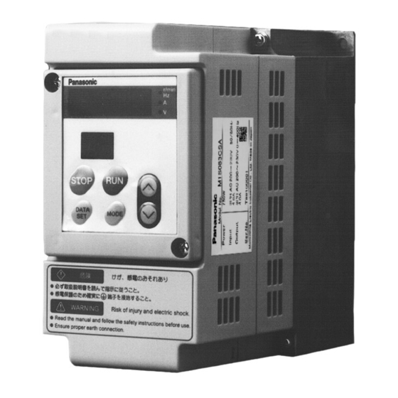
- Page 8 Introduction When unpacking ・Is the model correct? ・Was the equipment damaged in transport? If there is anything wrong with the equipment, contact your Panasonic dealer. Inverter model check Nameplate Model number Panasonic Panasonic Panasonic Panasonic M1S083CSA Model No Rated input Rated output...
- Page 9 Parts Identification Outer appearance GND terminal Operation panel ・ You remove Panasonic Panasonic Panasonic Panasonic operation panel using the ・ Volume is mounted for operation panel fixing the products with volume. screws. ・ You can remove the case by Operation panel...
- Page 10 Precautions Note the following precautions in order to use the inverter properly. Arrange for the power source capacity to be between 1.5 to 500kVA the inverter's capacity. An excessively high peak current may flow to the power input circuit, and damage the converter section if the wiring length between the power source and the inverter is shorter than 100 m with a power source exceeding 500kVA, or the phase- advancing capacitor is switched on the power source side.
- Page 11 Installation Install the inverter properly to prevent equipment failure or accidents. Inverter Installation location ① Install the inverter indoors in a place not exposed to rain or direct sunlight. The inverter is not waterproof. ② Install in a place not exposed to corrosive/flammable gases, grinding fluid, oil mist, metal powder or chips.
- Page 12 System Configuration and Wiring Wiring general view Main circuit No-fuse breaker (NFB) or Earth leakage breaker Used to protect the power line. Interrupts the circuit in the case of excessive current. * Use an anti-harmonic earth leakage breaker for the inverter. Noise filter (NF) Blocks noise from the power line.
- Page 13 Applicable peripheral equipment Wiring apparatus selection (1) Selection of no-fuse breaker, magnetic contactor, thermal relay, (Matsushita Electric Works No.) and wiring Inverter No. Applicabl No-fuse Magnetic Thermal Wiring (mm e motor breaker contactor relay Main Control circuit circuit (kW) (Rated current) (Contact configuration) (Current adjustment range) BBP25...
- Page 14 System Configuration and Wiring Wiring Standard wiring diagram Short (direct current reactor connection terminal) Motor PD P R/L1 U/T1 Power source S/L2 V/T2 T/L3 W/T3 Main circuit ●Connect to R/L1, S/L2 for single-phase 5V External frequency setting volume P Brake resistor FIN1 1/4W, 5kΩ, B characteristic connection terminal...
- Page 15 (2) Control terminal <Terminal screw size: M2, Tightening torque 0.25 ~ 0.3 N·m> Terminal No. Terminal name Function description Power source 5V terminal for fre- + 5VDC applied. I max. = 20 mA quency setting Power source 12V terminal for + 12VDC applied.
- Page 16 System Configuration and Wiring Precautions when wiring The inner circuit is still energized with a high voltage after the input power is turned off. Do not touch the inverter for at least 5 minutes after turning off the power. Main circuit (1) The inverter will be damaged if you invert the connections of the power input terminal and motor output terminal (U/L1, V/L2, W/L3).
- Page 17 Parameter Setting Setting Operation Panel r/min A V 5-digit LED 2-digit LED STOP RUN DATA MODE SET Frequency Hz is displayed when in the normal monitor mode. You can display synchronized rotations for the parameter " display power." Displays output frequency, set frequency or display power, cause of error, or 5-digit LED parameter.
- Page 18 Output frequency Power ON Monitor mode ↓ MODE ↓ △ Current MODE ↓ ▽ MODE Can set directly No. 0 ↓ speed setting with UP and Converter voltage DOWN keys. frequency command Note) Available when " selection" is set to MODE DATA SET ●...
- Page 19 Test Operation Pre-operation inspections After installing and wiring, inspect the following before running the inverter. (1) Is the wiring connected correctly? (Especially power input terminals R/L1, S/L2 and T/L3, output terminals U/T1, V/T2 and W/T3, load side short or ground) (2) Does input power comply with the rating? (3) Are there any places that could be shorted by wire cuttings, etc? (4) Are any screws or terminals loose?
- Page 20 Operation Method Selection of operation commands You can perform the following six kinds of operation using the frequency command and run command on the operation panel or using the terminal block with the MIS series inverters. Frequency command Run command Parameter setting Operation Terminal...
Need help?
Do you have a question about the M1S Series and is the answer not in the manual?
Questions and answers