Pace MBT250 Operation & Maintenance Manual
Hide thumbs
Also See for MBT250:
- Operation & maintenance instructions manual (12 pages) ,
- Operation, maintenance & instruction manual (9 pages) ,
- Installation, operation & maintenance manual (58 pages)
Table of Contents
Advertisement
Advertisement
Table of Contents

Related Manuals for Pace MBT250


Summary of Contents for Pace MBT250
- Page 1 MBT 250 SYSTEMS OPERATION & MAINTENANCE MANUAL...
-
Page 2: General Information
The "Quick Reference" guide is provided as a convenient reference for day-to-day operation of the system. If you encounter any difficulty operating your system, call your local authorized PACE dealer or contact PACE as shown on page iv of this manual. - Page 3 SensaTemp (closed-loop) temperature control system which provides up to 182 watts of total power to the three output channels (see Power Management, Page 12). Microprocessor controlled circuitry allows the user to quickly configure the system to their requirements and easily recalibrate the system to maintain accuracy and peak performance.
-
Page 4: System Configurations
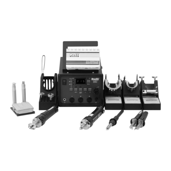
GENERAL INFORMATION System Configurations Power Source, 115 VAC, 60 Hz Power Source, 230 VAC 50 Hz PS-90 Soldering Iron SX-80 Sodr-X-Tractor TP-65 ThermoPic Handpiece TT-65 ThermoTweez Handpiece PS-90 Tip and Tool Stand SX-80 Tip and Tool Stand Tip Maintenance Station Pace Tip &... -
Page 5: Specifications
GENERAL INFORMATION SPECIFICATIONS POWER REQUIREMENTS MBT 250 - Version operates on 97-127 VAC, 50/60 Hz. 185 Watts, 1.6 Amp max, 100% Duty Cycle, Motor on. MBT250E - Version operates on 196-253 VAC, 50 Hz. 212 Watts, 0.92 Amp max, 100% Duty Cycle, Motor on. PHYSICAL PARAMETERS Size: 13.5 cm H x 16.5 cm W x 26 cm D (5.3"H x 6.5"W x 10.25"D) -
Page 6: Environmental Requirements
GENERAL INFORMATION NOTE Actual minimum and maximum Operating Tip Temperatures may vary depending on handpiece & tip selection. EOS/ESD Tip-To-GroundResistance: Less than 5 ohms (except on Soft Ground Systems). AC Leakage: Less than 2 millivolts RMS from 50Hz to 500Hz (except on Soft Ground Systems). -
Page 7: Parts Identification
GENERAL INFORMATION Parts Identification Listed below is a description of the system power source parts. Use Figures 1 & 2 as a guide. 1. CH 1 POWER RECEPTACLE - Provides power, tip ground, sensing circuitry and finger switch connection from MBT system to handpiece connected to Channel 1 (CH 1). 2. - Page 8 GENERAL INFORMATION 16. TIP SET LED - Flashes when TIP SET Key is pressed indicating that the system is in Tip Set Mode. 17. TIP OFFSET KEY - Allows the operator to adjust the Tip Offset Constant for the handpiece connected to the Current Channel.
- Page 9 GENERAL INFORMATION Parts Identification (Con't) Power Switch Earth Ground Controllable Receptacle Pressure Port AUTO Power SNAP-VAC Receptacle Port Power Power Receptacle Receptacle Digital Tip Offset Readout °F LED CH1 LED CH2 LED °F/°CKEY CH3 LED Tip Set °C LED CH Select Key Tip Set Key Tip Offset Key Scroll Up Key...
- Page 10 GENERAL INFORMATION AC Power CAL/SET Receptacle/ Key Lock Fuse Holder (Optional) Foot Fuse Pedal Receptacle Figure 2. Parts Identification, Rear View...
-
Page 11: Power Management
Iron and a SX-80 Sodr-X-Tractor handpiece on your MBT 250, and power a TT-65 ThermoTweez handpiece on your ST-TT system to suit your particular application. If you require assistance in the use of this product, contact your local authorized PACE dealer or PACE directly as shown on page iv of this manual. - Page 12 SAFETY The purpose of this "SAFETY" section is to inform users of the heading guidelines used in this manual to indicate special Notes, Cautions, Warnings or Dangers. Also included are recommended precautions which must be observed when operating or servicing this product. Heading Guidelines PACE adheres to the following Heading Guidelines (based on OSHA guidelines) when listing special information or precautions to be taken.
- Page 13 SAFETY Precautions The following are general safety precautions which personnel must understand and follow when using or servicing this product. These precautions may or may not be included elsewhere in this manual. CAUTIONS 1. Handpiece heaters and installed tips are hot when handpiece is powered on. DO NOT touch either the heater or tip.
- Page 14 SAFETY Safety Guidelines, English Language The following are safety precautions which personnel must understand and follow when using or servicing this product. 1. POTENTIAL SHOCK HAZARD - Repair procedures on PACE products should be performed by Qualified Service Personnel only. Line voltage parts may be exposed when the equipment is disassembled.
- Page 15 SAFETY 3. Angeschlossene SensaTemp Heizelemente von Handwerkzeugen und installierte Loetspitzen sind heiss wenn das System eingeschaltet ist oder erst vor kurzer Zeit ausgeschaltet wurde. Heizelement und Loetspitze nicht beruehren. Verbrennungsgefahr. 4. PACE Tip & Tool und andere Handwerkzeugablagen sind so konstruiert, dass ein versehentliches Beruehren des dazugehoerendes Handwerkzeuges vermieden wird.
- Page 16 SAFETY Misure di Sicurezza, Italiana Lingua Le seguenti instruzioni sono misure di sicurezza che il personale deve comprendere e seguire quando utilizza o ripara I prodotti PACE. 1. EVENTUALI RISCHI DI SHOCK ELETTRICO- Si consiglia di far eseguire le operazioni di riparazione dei prodotti PACE, da un servizio di personale qualificato.
- Page 17 SAFETY Guidelines de Segurança, Portuguese Lingua Segeum-se precauções de segurança que os operadores devem compreender e seguir ao utilizar ou reparar produtos PACE. 1. Perigo de choque eléctrico - Os procedimentos de reparação em produtos PACE, devem ser apenas efectuados por pessoal qualificado. Linhas de alimentação podem ficar expostas ao desmontar o equipamento.
-
Page 18: Säkerhetsföreskrifter, Svenska
SAFETY 3. Las herramientas SensaTemp tienen sus calentadores y las puntas instaladas calientes cuando la herramienta esta encendida y por un periodo de tiempo después de apagar el equipo. No toque el calentador o la punta. Las quemaduras severas pueden resultar. 4. - Page 19 SET-UP System Set up the MBT 250 system using Figures 3 through 11 and the following steps. 1. Store the shipping container(s) in a convenient location. These containers can be reused to prevent damage if you ship or store the system. 2.
-
Page 20: Handpiece Vacuum/Pressure
SET-UP 9. To avoid confusion among handpieces, PACE recommends the use of colored cable markers (P/N 6993-0136 Cable Marker Kit) to identify the particular handpiece . Attach any two like colored markers, one to each end of the handpiece power cable or air hose. Select and use a different colored marker for each handpiece. - Page 21 SET-UP Procedures TRADITIONAL METHOD 1. Connect the 54 inch (137cm) length of Air Hose to the metal tube in the back of the air handpiece. Fitting Air Hose 2. Insert the ribbed end of a Male Quick Connect Hose Mount Fitting (P/N 1259-0087) into the free end of the 54 inch (137cm) Figure 7.
- Page 22 SET-UP TRADITIONAL METHOD (CONT'D) 5. Connect the handpiece power cable connector plug to one of the Power Output Receptacles. For convenience, PACE recommends the use of CH 3 for air handpieces. NOTE If more than one air-operated handpiece is connected Figure 9.
- Page 23 SET-UP 2. Insert a Male Quick Connect Hose Mount Fitting (attached to VisiFilter assembly) into the Female AUTO SNAP-VAC Port on the front panel of the power source. 3. Attach the ribbed end of a Male Quick Connect Hose Mount Fitting (P/N 1259-0087) to each end of the 54 inch (137cm) translucent Air Hose.
-
Page 24: Quick Start - Basic Operation
Quick Start - Basic Operation Introduction The MBT 250 systems are very easy to operate. As received from the factory, the system can be quickly set up for use in standard soldering/desoldering operations. Simply perform the following Quick Start Procedure to begin system operation. - Page 25 Quick Start - Basic Operation 3. Perform the following to set handpiece tip temperatures. a) Press the TIP SET Key. b) Immediately press the Scroll Up (s) Key to increase the desired Tip Temperature. Press the Scroll Down (t) Key to decrease the Tip Temperature. c) Press the TIP SET Key.
-
Page 26: Operation
Operation Definitions Please read and become familiar with each of the following definitions. Each term is used repeatedly in the following operational procedures to avoid any possible confusion as to the intent of any particular instruction. ACTIVE CHANNEL - Any channel with a connected handpiece. AUTOMATIC POWER DOWN - Feature which turns off power to all three channels 90 minutes after all Active Channels have entered Temperature Setback. -
Page 27: Key Lock Feature
Operation System POWER UP 1. Ensure that the system is properly prepared for operation. Refer to the "Set-Up" portion of this manual. The handpieces selected for your application should be connected to the unit. Remember, PACE recommends connecting any air handpiece (which requires a vacuum hose) to channel number 3 (CH 3). - Page 28 Operation CHANNEL LED OPERATION 4. The Channel LED (CH 1, CH 2 or CH 3) of the first Active Channel encountered by the system (channel with connected handpiece) will be illuminated. This is the Current Channel. If no channels are active, "E-1"...
-
Page 29: Panel Controls
Operation PANEL CONTROLS 8. With three handpieces connected to the system, press the CH SELECT Key several times to observe the lighting of the CH 1, CH 2 & CH 3 LEDS. Each subsequent pressing will turn an LED off and turn the next Active Channel’s LED on. - Page 30 Operation PANEL CONTROLS (CONT'D) 11. Press the °F/°C Key several times to observe the alternating illumination of the °F & °C LEDs. Each subsequent pressing of the key will turn one LED on and the other off. Also notice as the Digital Readout changes to display the Operating Tip Temperature in °F when the °F LED is illuminated and in °C when the °C LED is illuminated.
- Page 31 Operation NOTE Refer to "Tip & Temperature Selection" for a complete discussion of Tip Tempera- ture Offset function. 15. Press the TIP OFFSET Key once to enter Tip Temperature Offset Mode. Immediately press and hold the Scroll Up Key. Observe the displayed Tip Offset Constant increase, first in 1° and then in 10° increments.
- Page 32 Operation PANEL CONTROLS (CONT’D) 18. The system will retain stored Set Tip Temperatures and Tip Offset Constants even when power is removed. 19. Note the Current Channel displayed on the system. Turn the POWER Switch to the OFF ("0") position. Turn the switch back to the ON ("1") position.
- Page 33 Operation 26. Using the CH SELECT Key, select each Active Channel in sequence, making it the Current Channel (temperature information displayed on Digital Readout). Using the procedures described in previous steps 9 thru 17 and step 25 as a reference, enter and store desired Tip Temperature information into system memory.
- Page 34 Operation Factory Settings The MBT 250 systems come equipped with a number of features which may be adjusted, enabled or disabled as desired by the user. Listed below are the features and factory settings of each. To change and/or learn about any of these features, refer to the applicable part of the "Calibration"...
- Page 35 Operation Tip & Temperature Selection With any heating system, actual tip temperatures can differ greatly from temperature control settings. PACE’s unique "Tip & Temperature Selection System" allows you to select and maintain True Tip Temperatures for any size and type of tip and handpiece using the appropriate Tip Temperature Offset value. Included with your system is a Chart Holder which holds Procedural Instructions, a Quick Reference Guide, a Customer Log and a Chart(s) for each handpiece purchased.
- Page 36 Calibration Introduction In Calibration (CAL) Mode, you can: 1. Change the Upper and Lower Temperature limits for each channel independently. 2. Set the Default Temperature scale to °F or °C as desired. 3. Enable or disable the Auto Temperature Setback/Power Down features. 4.
- Page 37 Calibration ENTERING CALIBRATION (CAL) MODE 2. Place POWER Switch in the "OFF" ("0") position. 3. Press and hold the TIP SET and Scroll Down Keys together. 4. Place POWER Switch in the ON ("1") position. All of the system LEDs will light. The Temperature Display will read "888"...
- Page 38 Calibration °F/°C READOUT DEFAULT 6. Press and release the TIP SET Key. The Digital Readout will display "S - X" (X = "-" or 1-9). Either the °F or °C LED will be on. This is the default temperature scale of the Digital Readout (e.g., if the °C LED is on, the Digital Readout will display Tip Temperatures and Tip Offset Constant values in °C).
-
Page 39: Automatic Power Down
Calibration AUTOMATIC POWER DOWN 10. The Automatic Power Down feature operates when (and only when) the Automatic Temperature Setback feature is enabled. No additional steps are necessary. For example, power to all channels is turned off 90 minutes after the last Active Channel’s Tip Temperature is set back. For additional information on this feature, refer to the "Automatic Power Down"... - Page 40 Calibration A) LOWER TEMPERATURE LIMIT SET POINT ( CONT'D) 14. Press and release the TIP SET Key to store the displayed value into memory. B) UPPER TEMPERATURE LIMIT SET POINT 15. The Digital Readout now displays "H-X" (X = 1-9). This is the stored value of the Upper Temperature Limit in increments of 100°F.
- Page 41 Calibration 18. Disconnect the handpiece from the Current Channel’s Power Output Receptacle and insert the "C-1" Calibration Module. DIGITAL READOUT ACCURACY Figure 22. Insert "C-1" Module 19. Press and release the TIP SET Key. The Digital Readout will flash "- - -" to indicate that the system microprocessor controlled temperature sensing and display circuitry is recalibrating one aspect of the system circuitry.
- Page 42 Calibration DIGITAL READOUT ACCURACY (CONT'D) 22. The system has now stepped to the next Active Channel. Repeat steps 12 through 21 to calibrate this channel. If all channels have been calibrated, proceed to step 23. 23. Press and release the TIP OFFSET Key two times to exit Calibration Mode. All values, features and defaults entered during the calibration are now stored in memory and all Set Tip Temperatures are turned "OFF".
- Page 43 Calibration Digital Readout Message Codes Listed below are Message Codes and a description of each which may be displayed on the Digital Readout during the Calibration procedure. DISPLAY DESCRIPTION MESSAGE Indicates system is ready to process Digital Readout accuracy C-1 OR C-2 calibration for a particular channel using the appropriate calibration module.
- Page 44 Temperature Setback Operation Introduction The MBT 250 systems are equipped with a Temperature Setback feature which, when enabled, will preserve tip life and reduce energy consumption. Procedure ACTIVATION There are two ways in which the system will enable the Temperature Setback feature. 1.
- Page 45 Temperature Setback Operation OPERATION 1. Temperature Setback for each channel is indicated by the following. a) The Current Channel LED will flash off once every 2 seconds when that channel is in Temperature Setback Mode. b) Any Active, non-Current Channel LED will flash on once every 2 seconds when that channel is in Temperature Setback Mode.
- Page 46 Temperature Setback Operation 2. For any individual channel, the attached handpiece may be disconnected and reconnected. The previously stored Set Tip Temperature will be restored as in method #1, but the Tip Offset Constant value will change to the default value of "3" for °C ("6" for °F). To exit Temperature Setback Mode for all channels, do either of the following.
-
Page 47: Factory Default
Temperature Setback Operation Factory Default As received from the factory, the system will not go into Automatic Temperature SetBack. To enable this feature, refer to the "Calibration" portion of this manual. The Automatic Power Down feature of the MBT 250 systems is a safety feature which removes power from all channels 90 minutes after all Active Channels have entered the Automatic Temperature Setback Mode. -
Page 48: Quick Reference
Quick Reference The Quick Reference Chart shown below may be used as a guide for quickly changing any particular parameter stored within the system. Locate the parameter you wish to change in the column marked "ACTION" and follow the simple instructions given under "Procedure". Remember that if the system is equipped with a Key Lock feature, the switch must be turned to the UNLOCK position before making any changes. -
Page 49: Auto Power
Quick Reference ACTION PROCEDURE PRESS & HOLD POWER ON RELEASE AFTER 3 SECONDS ENTER CALIBRATION (CAL) MODE SET DEFAULT ˚F PRESS TEMP SCALE OFFSET ˚C KEYS (°F/°C) ** (Press CHANGE LOWER PRESS SELECT OFFSET TEMP LIMIT ** KEYS Twice) CHANGE UPPER PRESS SELECT TEMP LIMIT **... - Page 50 Quick Reference ACTION PROCEDURE PRESS & HOLD RELEASE AFTER 1 SECOND MANUAL SETBACK ON ALL ACTIVE CHANNELS PRESS & HOLD RELEASE AFTER 1 SECOND EXIT SETBACK ON ALL ACTIVE CHANNELS Table 3. Quick Reference Chart (Continued)
-
Page 51: Corrective Maintenance
Corrective Maintenance VisiFilter Element Replacement Follow the procedure listed below to replace the VisiFilter element when it becomes clogged or discolored. 1. Disconnect the handpiece air hose by gently turning and pulling the coupled Fittings. 2. Disconnect the Visifilter and hose assembly from the Power Source by gently turning and pulling the male Fitting inserted into the AUTO SNAP-VAC Port. -
Page 52: Power Source
Corrective Maintenance Power Source Most malfunctions are simple and easy to clear. Refer to Table 4 below to clear these malfunctions. If you encounter any difficulty clearing the malfunction, contact PACE Technical Support directly at Tel. (toll free) 1-888-535-PACE(7223)or(301)490-9860,FAX(301)483-7030. Symptom Probable Cause Solution Digital Readout is blank. - Page 53 Corrective Maintenance Handpieces The following "Heater Assembly Checkout Procedures" (Table 4) are applicable to all PACE handpieces except for the TT-65 ThermoTweez & DTP-80 Dual ThermoPik handpieces. Refer to the respective handpiece manuals for troubleshooting procedures pertinent to those handpieces. Use the Digital Readout Message Codes ("E-1", "E- 2", "E-3"...
-
Page 54: Spare Parts
Spare Parts Power Source Listed below are the power source parts which may be ordered directly from PACE sales or your local authorized PACE distributor. For handpiece replacement parts, refer to the associated Operation and Maintenance Manual. To obtain power source parts other than those shown, contact your local PACE distributor or PACE directly at Telephone (301) 490-9860, Fax (301) 483-7030. - Page 55 Spare Parts Handpieces Listed below are the handpieces available from PACE. The list is current at time of publication. Contact your local authorized PACE distributor for additional information. Item Description Part Number SensaTemp Handpieces PS-90 Soldering Iron 6010-0131-P1 SX-80 Sodr-X-Tractor 6010-0106-P1 TJ-70 ThermoJet 7023-0002-P1...
- Page 56 Spare Parts System Accessories Listed below are the system accessories available from PACE. The list is current at time of publication. Contact your local authorized PACE distributor for additional information. Item # Description PACE Part Number Tip Maintenance Station 6993-0138 Replacement Sponge for Tray (Qty.
-
Page 57: Warranty
Warranty LIMITED WARRANTY PACE warrants that this equipment will be free of defects in materials and workmanship for a period of one (1) year from the date of receipt by the first user. This warranty does not cover repair or replacement required as a result of misuse, mishandling or improper storage.
Need help?
Do you have a question about the MBT250 and is the answer not in the manual?
Questions and answers