
Related Manuals for Pace MBT 301


Summary of Contents for Pace MBT 301
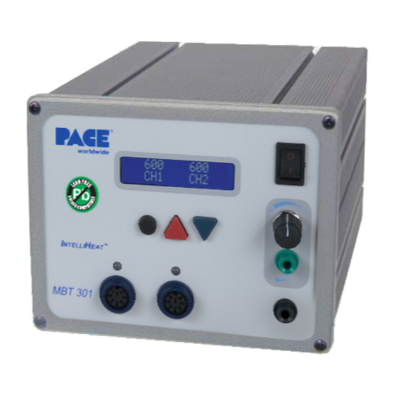
- Page 1 Operation and Maintenance Manual for the ® PACE MBT 301 Digital Soldering/Desoldering System P/N 5050-0560 Rev. C: 3-15 This manual applies to: Version 2.3...
-
Page 2: Table Of Contents
Hello Message ..................16 Corrective Maintenance ................ 17 Packing List ................... 17 Spare Parts ................... 17 Service ......................17 LIMITED WARRANTY STATEMENT ........... 18 Contact Information ................18 ©2013 PACE Worldwide, Southern Pines, North Carolina All Rights Reserved Page 2 of 18 ... -
Page 3: General Information
The MBT 301 unit is available in either the 115 VAC or 230 VAC versions. The 230 VAC version system bears the CE Conformity Marking which assures the user that it conforms to all the requirements of (EU) directive EMC 89/336/EEC &... -
Page 4: Eos/Esd
SMDs. TJ-80 Kit P/N 6993-0270-P1 Handpiece only P/N 6010-0153-P1 MBT 301 Handpieces tips A complete list of available handpiece tips is available from your local PACE distributor or online at www.paceworldwide.com. ©2013 PACE Worldwide, Southern Pines, North Carolina All Rights Reserved Page 4 of 18 ... -
Page 5: Parts Identification
CH 2 POWER RECEPTACLE - Provides power, tip ground, sensing circuitry and finger switch connection from MBT system to handpiece connected to Channel 2 (CH 2). ©2013 PACE Worldwide, Southern Pines, North Carolina All Rights Reserved Page 5 of 18... - Page 6 14. FUSE - Provides overload protection for system. 15. FOOT PEDAL RECEPTACLE - Input for Foot Pedal (optional), which activates vacuum or pressure to the air-operated handpieces. ©2013 PACE Worldwide, Southern Pines, North Carolina All Rights Reserved Page 6 of 18 ...
-
Page 7: Safety Guidelines
If you require assistance in the use of this product, contact your local authorized PACE dealer or PACE directly as shown on page 15 of this manual Safety Guidelines The following are safety precautions that personnel must understand and follow when using or servicing this product. -
Page 8: Safety
3. Be careful when using the MBT 301 in places where there are combustible materials. Heat may be conducted to combustible materials, which are out of sight. 4. Do not apply heat from the MBT 301 to one place for a long time. 5. Do not leave the MBT 301 unattended while powered on. -
Page 9: Servicing Precautions
Safety Electrical Requirements The MBT 301 unit draws approximately 240 VA (240Watts), which is listed on the nameplate on the power source rear panel. A separate, dedicated AC supply line circuit may be required to adequately power the unit/system. If your power outlet cannot provide suitable power, arrange for a qualified, licensed electrician to install one for you. - Page 10 AC power Figure 3b outlet. The system is now ready for operation. 10. Read the "OPERATION" section of this manual thoroughly before operating the system. ©2013 PACE Worldwide, Southern Pines, North Carolina All Rights Reserved Page 10 of 18 ...
-
Page 11: Attaching Tip & Tool Stand
Optional Instant-Setback Cubby Figure 4 The optional Instant SetBack Cubby is available for use with the MBT 301 and will only function with the TD-100 handpiece. When connected, it automatically puts the system into Setback mode when the TD- 100 is placed in the cubby. The Instant Setback Cubby will only function with the TD-100 Handpiece.The instant SetBack receptacles are located on the back panel. -
Page 12: Definitions
Normal Operation: Normal operating mode of the system in which the Operating Tip Temperature is displayed. Password: The Password feature of the MBT 301 system will prevent unauthorized alteration of stored system temperature parameters and feature settings. If a Password has been installed, the LCD Display will display an instruction to enter the password. -
Page 13: Led Operation
(see Corrective Maintenance section). Operation Accessing Programming Menu The menu driven LED Display of the MBT 301 system allows you to easily customize your system. By accessing the programming menu, you can: • Enter, remove or change a Password. -
Page 14: Set Upper Limit
UP Key to enter increase the auto-off time. When enabled, the Auto Off safety system of the MBT 301 system turns off the power to the Handpiece 1- 90 minutes after entering Temperature Setback. When the system has entered Temperature Setback, an Auto Off timer within the system circuitry will start running if Auto Off is turned on. -
Page 15: Set Lcd Contrast
LCD contrast. The range of contrast is 1 to 100. Press and release the PROGRAM Key to move to the next step. ©2013 PACE Worldwide, Southern Pines, North Carolina All Rights Page 18 of 18 ... -
Page 16: Set Led Backlite
2. Clear any offset from the system by disconnecting the handpiece from the system. Re- connect the handpiece and proceed to step 2. 3. A BLINKING dot will appear in the center of the "C" in channel (“CH”). Set the MBT 301 to 700°F to (370°C). -
Page 17: Corrective Maintenance
5050-0459 Spare Parts Item # Description PACE Part Number Fuse, 2.0 A, 125 V, Lag Time (MBT 301) 1159-0275-01-P5 Fuse, 1.25 A, 230 V, Lag Time (MBT 301E) 1159-0275-02-P5 ©2013 PACE Worldwide, Southern Pines, North Carolina All Rights Page 18 of 18... -
Page 18: Service
Please contact PACE or your local distributor for service and repair. PACE Incorporated retains the right to make changes to specifications contained herein at any time, without notice. Contact your local authorized PACE Distributor or PACE Incorporated to obtain the latest specifications.
Need help?
Do you have a question about the MBT 301 and is the answer not in the manual?
Questions and answers