Table of Contents
Advertisement
Quick Links
Advertisement
Table of Contents

Related Manuals for Pace MBT 201


Summary of Contents for Pace MBT 201
- Page 1 MBT 201 SYSTEMS OPERATION & MAINTENANCE MANUAL...
- Page 2 MANUAL NO. 5050-0381 REV. E...
- Page 3 PACE Incorporated retains the right to make changes to specifications contained herein at any time, without notice. Contact your local authorized PACE Distributor or PACE Incorporated to obtain the latest specifications. The following are trademarks and/or servicemarks of PACE Incorporated, Laurel Maryland USA:...
-
Page 4: Table Of Contents
Power Source ........................26 Accessory Kit, MBT 201 ....................27 Table Page Table Heater Assembly Chekout Procedures ............24 Table Power Source Corrective Maintenance ............25 Table Power Source Replacement Parts ..............26 Table IV MBT 201 Accessory Kit ................. 27... -
Page 5: General Information
The MBT 201 systems are available in a 115 VAC (97-127 VAC) version or a 230 VAC (196-253 VAC) version. The 230 VAC version system bears the CE Conformity Marking which assures the user that it conforms to all the requirements of council directive EMC 89/336/EEC. -
Page 6: Specifications
General Information Specifications POWER REQUIREMENTS MBT 201 System - Version operates on 97-127 VAC, 50/60 Hz. 138 Watts, 1.2 Amp typical; 184 Watts, 1.6 Amp maximum MBT 201E System - Version operates on 196-264 VAC, 50 Hz. 138 Watts, 0.6 Amp typical; 199 Watts, 0.9 Amp maximum VACUUM AND AIR Measurements at front panel AUTO SNAP-VAC and Controllable PRESSURE Ports of power source. - Page 7 Size: 13.5 cm H X 16.5 cm W X 20.3 cm D (5.3 in. H X 6.5 in. W X 8.0 in. D) Weight: MBT 201 3.7 kg. (8.1 lbs.) MBT 201E 3.7 kg. (8.1 lbs.) TEMPERATURE SPECIFICATIONS Tip Temperature Range: 232°C to 482°C (450°F to 900°F), nominal.
-
Page 8: Capabilities
PS-90 Soldering Iron - Standard handpiece on MBT 201 & MBT 201E systems. Provides a wide range of SMD and thru-hole installation and removal capability as well as unsurpassed thermal performance on heavy, multilayer thru-hole assemblies at safe, lower working temperatures. - Page 9 General Information Optional Handpieces TJ-70 ThermoJet Handpiece - Provides safe, rapid installation of SMDs including chip components, SOTs, SOICs, PLCCs, LCCCs and FlatPacks. The slim-line design and precision focused air flow lets you easily target controlled heat right at the solder joints without damaging the board or adjacent components.
-
Page 10: Product Application
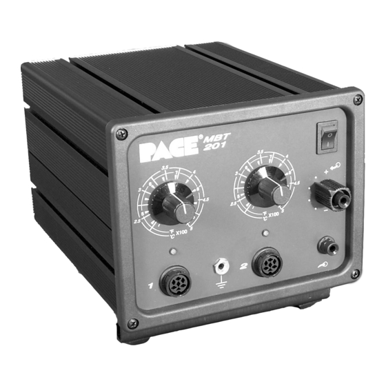
These products are very versatile and may be used to satisfy a variety of application requirements. If you require assistance in the use of this product for your particular application, contact your local authorized PACE distributor or PACE directly as shown on page ii. Parts Identification 1. - Page 11 General Information CH 1 Power Switch Variable Temperature Control CH 2 Variable Temperature Control CH 1 LED Controllable Pressure Port CH 1 Power Receptacle CH 2 LED Auto Snap- Earth Vac Port Ground Receptacle CH 2 Power Receptacle AC Power Receptacle Foot Pedal Receptacle...
- Page 12 General Information 11. POWER CORD - Provides main power to system from AC outlet to AC Power Receptacle. 12. AC POWER RECEPTACLE/FUSE HOLDER - Receptacle for providing power to the system from AC outlet through Power Cord, and location of fuse which protects system from overcurrent conditions.
-
Page 13: Safety
Heading Guidelines PACE adheres to the following Heading Guidelines (based on OSHA guidelines) when listing special information or precautions to be taken. Especially important are all procedures and practices which, if not strictly observed, could result in injury or loss of life. -
Page 14: Safety Guidelines, English Language
Always store the handpiece in its holder. Be sure to place the handpiece in its holder after use and allow to cool before storing. 5. Always use PACE systems in a well ventilated area. A fume extraction system such as those available from PACE are highly recommended to help protect personnel from solder flux fumes. -
Page 15: Safety Guidelines,German Language
System eingeschaltet ist oder erst vor kurzer Zeit ausgeschaltet wurde. Heizelement und Loetspitze nicht beruehren. Verbrennungsgefahr. 4. PACE Tip & Tool und andere Handwerkzeugablagen sind so konstruiert, dass ein versehentliches Beruehren des dazugehoerendes Handwerkzeuges vermieden wird. Bewahren Sie das Handwerkzeug nach Gebrauch stets in der Ablage auf. -
Page 16: Safety Guidelines, French Language
Des brûlures sévères peuvent en résulter. 4. Les outils PACE et leurs pannes ainsi que le support sont dessinés de manière spécifique afin de protéger l'utilisateur/opérateur de brûlures accidentelles. Reposer toujours les outils après chaque utilisation dans leurs étuis/supports afin de permettre leur refroidissement. -
Page 17: Safety Guidelines, Portuguese Language
5. Utilizzare sempre I stazioni PACE in una zona be aerata per proteggere il personale dai fumi. É fortemente raccomandato un sistema di aspirazione (dei fumi) come quello disposta dalla PACE. -
Page 18: Safety Guidelines,Spanish Language
No toque el calentador o la punta. Las quemaduras severas pueden resultar. 4. El Soporte de punta y Herramienta PACE se diseñan específicamente para el uso con las herramientas asociadas y las almacena de una manera que protege al usuario de las quemaduras accidentales. -
Page 19: Safety Guidelines, Swedish Language
Följande säkerhetsföreskrifter måste förstås och följas av personal som använder eller utför service på PACE produkter. 1. RISK FÖR STRÖMSTÖT - Service / Reparation av PACE produkter får endast utföras av aktoriserad service personal. Strömförande delar kan kommas åt när produkten är isärplockad. -
Page 20: Set-Up
SET-UP System Using Figures 2, 3 and 4 as a guide, set up the MBT 201 system using the following steps. 1. Store the shipping container(s) in a convenient location. Re-use of these containers will prevent damage if you store or ship the system. - Page 21 Figure 3. Handpiece Connection 10. To avoid confusion among handpieces on MBT 201 systems, PACE recommends the use of colored markers (P/N 6993-0136 Cable Marker Kit) to identify the particular handpiece power cable and/or air hose. Attach any two like colored markers, one to each end of the handpiece power cable or air hose.
-
Page 22: Handpiece Vacuum Pressure
Handpiece Vacuum/Pressure AIR HOSE CONNECTION There are two methods of attaching the Air Hose from the PACE power source to the air handpiece. Select the method which best suits your needs. The Quick Connect Method is best suited for configurations where multiple air handpieces may be in use. The Traditional Method is best suited for single air handpiece configurations. - Page 23 Set-up 3. Prepare a quick connect Air Hose by inserting a Metal Hose Clamp (P/N 1211-0036) & a Male Quick Connect Hose Mount Fitting (P/N 1259- 0087) into each end of a 54 inch (137cm) length of Air Hose. Push the ridged ends of the fittings into the hose;...
- Page 24 Set-up TRADITIONAL METHOD 1. Connect the 54 inch (137cm) length of Air Hose to the metal tube in the back of each air handpiece. 2. Insert a Male Quick Connect Hose Mount Fitting (P/N 1259- 0087) to the free end of the 54 inch (137cm) length of Air Hose.
-
Page 25: Quick Start - Basic Operation
Operation - Quick Start Quick Start Procedure The MBT 201 systems are very easy to operate. As received from the factory, the system can be quickly set up for use in standard soldering/desoldering operations. Simply perform the following Quick Start Procedure to begin system operation. -
Page 26: Operation
True Tip Temperature for any size and type of tip using the appropriate Tip Offset compensation value. PACE recommends the use of the Tip & Temperature Selection System Booklet (PACE P/N 5050- 0251) included with your system) as a guide to accurately set and maintain a True Tip Temperature. -
Page 27: Corrective Maintenance
Corrective Maintenance CORRECTIVE MAINTENANCE VisiFilter Element Replacement Follow the procedure listed below to replace the VisiFilter Element when it becomes clogged or discolored. 1. Disconnect the handpiece air hose by gently turning and pulling the Coupled Fittings. 2. Disconnect the Visifilter and hose assembly from the Power Source by gently turning and pulling the Male Fitting inserted into the AUTO SNAP-VAC Port. -
Page 28: Handpieces
Corrective Maintenance CORRECTIVE MAINTENANCE Handpieces The following "Heater Assembly Checkout Procedures" are applicable to all PACE handpieces except for the TT-65 ThermoTweez handpiece. Refer to either of the TT-65 manuals (P/N 5050-0300 or 5050-0336) for troubleshooting procedures pertinent to that handpiece. -
Page 29: Power Source
See Table l or refer to handpiece Other handpieces work on Manual. Power Source channel. No heat on handpiece. Defective control circuit. Contact PACE Technical Support Other handpieces do not work on Power Source channel. Table II. Power Source Corrective Maintenance... -
Page 30: Replacement Parts
REPLACEMENT PARTS Power Source Listed below are the replacement parts which may be ordered through your local authorized PACE distributor. To inquire about parts other than those listed below, contact PACE as shown on page ii. PACE Part Number Item Description... -
Page 31: Accessory Kit, Mbt 201
Replacement Parts REPLACEMENT PARTS Accessory Kit Listed below are items included in MBT 201 System Accessory Kit (P/N 7950-0112). Ite m D e s c rip tio n P A C E P a rt N u m b e r... - Page 32 Warranty l l i r i f t l u s ’ f i t l l i . y t r i f l l a t i t t l i f e l l y l l r i f , l l i i l i...
Need help?
Do you have a question about the MBT 201 and is the answer not in the manual?
Questions and answers