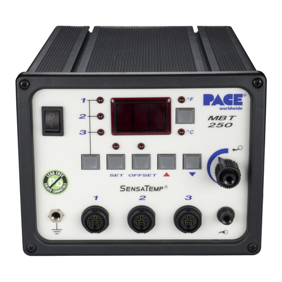
Pace MBT 250 Operation, Maintenance & Instruction Manual
Calibration kit
Hide thumbs
Also See for MBT 250:
- Operation & maintenance manual (58 pages) ,
- Operation & maintenance instructions manual (12 pages) ,
- Installation, operation & maintenance manual (58 pages)
Advertisement
Quick Links
OPERATION
INTRODUCTION
The following procedure will allow you to effectively calibrate your MET 250/220 system to insure
accuracy and maintain peak performance.
Perform the following procedure step by step, in sequence, to:
1. Alter Tip Temperature values.
2. Alter Tip Temperature Offset values.
3. Determine and/or alter feature status and defaults stored in the system.
4. Recalibrate the system for accuracy.
PROCEDURE
KEYLOCK OPTION
KEYLOCK
1. An optional KeyLock feature is available from PACE which
prevents unauthorized alteration of stored data or calibration of the
system. Check the rear panel of the system power source. If the
KeyLock feature is present there will be a KeyLock switch located in
the upper left portion of the panel. Use the key to turn the switch to
the "Unlock" position. If the feature is not present, there will be a
round plastic filler plug present at that location.
The KeyLock switch-must be turned to the "UNLOCK!" position to alter
any of the data stored in the memory or to recalibrate the system
©2012 PACE Incorporated, Southern Pines, NC All Rights Reserved. Printed in the USA
& MAINTENANCE INSTRUCTIONS
MBT 250/220
CALIBRATION
PACE P/N 6993-0133-P1
NUMBER
5050-0288
NOTE
www.paceworldwide.com
MANUAL
KIT
REV. B
Advertisement

Summary of Contents for Pace MBT 250
- Page 1 NOTE The KeyLock switch-must be turned to the "UNLOCK!" position to alter any of the data stored in the memory or to recalibrate the system ©2012 PACE Incorporated, Southern Pines, NC All Rights Reserved. Printed in the USA www.paceworldwide.com...
-
Page 2: Entering Calibration Mode
Down Keys. The Temperature Display will now read “CAL” and only the three Channel LEDs will remain lit signifying that the system is now in calibration Mode ©2012 PACE Incorporated, Southern Pines, NC All Rights Reserved. Printed in the USA www.paceworldwide.com... - Page 3 9. Press the Tip Temperature Set Key to store the °F/°C default and Automatic Setback value in system memory. The Digital Readout will revert to display "CAL" and only the Channel 1 LED will remain ©2012 PACE Incorporated, Southern Pines, NC All Rights Reserved. Printed in the USA www.paceworldwide.com...
-
Page 4: Automatic Shutdown
Digital Readout will now display "L-X" (X = 1-9). This is the stored value of the Lower Temperature Limit in increments of 100°F. For example, if the "L-5" is displayed, the lower limitis500°F. ©2012 PACE Incorporated, Southern Pines, NC All Rights Reserved. Printed in the USA www.paceworldwide.com... - Page 5 15. The Digital Readout now displays "H-X" (X =1-9). This is the stored value of the Upper Temperature Limit in increments of 100°F in the same manner as the Lower ©2012 PACE Incorporated, Southern Pines, NC All Rights Reserved. Printed in the USA www.paceworldwide.com...
- Page 6 Key. The Digital Readout will flash (- - - “ to indicate that the system microprocessor circuitry is recalibrating one aspect of the system circuitry, “C-2” will now be displayed. ©2012 PACE Incorporated, Southern Pines, NC All Rights Reserved. Printed in the USA www.paceworldwide.com...
- Page 7 “OFF”. All channel Tip Temperature Offset settings are set to the default value of 6°F (3°C). ©2012 PACE Incorporated, Southern Pines, NC All Rights Reserved. Printed in the USA www.paceworldwide.com...
- Page 8 TEMPERATURE DISPLAY MESSAGE CODES Listed below are message codes and a description of each which may be displayed on the system power source digital readout during the calibration procedure. ©2012 PACE Incorporated, Southern Pines, NC All Rights Reserved. Printed in the USA www.paceworldwide.com...
- Page 9 WITH ANY OF THE PRODUCTS. Warranty service may be obtained by contacting the appropriate PACE Company or local Authorized PACE distributor as set forth below to determine if return of any item is required, or if repairs can be made by the user in the field.


Need help?
Do you have a question about the MBT 250 and is the answer not in the manual?
Questions and answers